


Version 1.0
Published September 2017
Copyright©2017 ASRock INC. All rights reserved.
Copyright Notice:
No part of this documentation may be reproduced, transcribed, transmitted, or translated in any language, in any form or by any means, except duplication of documentation by the purchaser for backup purpose, without written consent of ASRock Inc.
Products and corporate names appearing in this documentation may or may not be registered trademarks or copyrights of their respective companies, and are used only for identification or explanation and to the owners’ benefit, without intent to
infringe.
Disclaimer:
Specifications and information contained in this documentation are furnished for informational use only and subject to change without notice, and should not be constructed as a commitment by ASRock. ASRock assumes no responsibility for any errors or omissions that may appear in this documentation.
With respect to the contents of this documentation, ASRock does not provide warranty of any kind, either expressed or implied, including but not limited to the implied warranties or conditions of merchantability or fitness for a particular purpose.
In no event shall ASRock, its directors, officers, employees, or agents be liable for any indirect, special, incidental, or consequential damages (including damages for loss of profits, loss of business, loss of data, interruption of business and the like), even if ASRock has been advised of the possibility of such damages arising from any defect or error in the documentation or product.
This device complies with Part 15 of the FCC Rules. Operation is subject to the following two conditions:
(1)this device may not cause harmful interference, and
(2)this device must accept any interference received, including interference that may cause undesired operation.
CALIFORNIA, USA ONLY
The Lithium battery adopted on this motherboard contains Perchlorate, a toxic substance controlled in Perchlorate Best Management Practices (BMP) regulations passed by the California Legislature. When you discard the Lithium battery in California, USA, please follow the related regulations in advance.
“Perchlorate Material-special handling may apply, see www.dtsc.ca.gov/hazardouswaste/ perchlorate”
ASRock Website: http://www.asrock.com

AUSTRALIA ONLY
Our goods come with guarantees that cannot be excluded under the Australian Consumer Law. You are entitled to a replacement or refund for a major failure and compensation for any other reasonably foreseeable loss or damage caused by our goods. You are also entitled to have the goods repaired or replaced if the goods fail to be of acceptable quality and the failure does not amount to a major failure. If you require assistance please call ASRock Tel : +886-2-28965588 ext.123 (Standard International call charges apply)
The terms HDMI™ and HDMI High-Definition Multimedia Interface, and the HDMI logo are trademarks or registered trademarks of HDMI Licensing LLC in the United States and other countries.
CE Warning
This device complies with directive 2014/53/EU issued by the Commision of the European Community.
This equipment complies with EU radiation exposure limits set forth for an uncontrolled environment.
This equipment should be installed and operated with minimum distance 20cm between the radiator & your body.
Operations in the 5.15-5.35GHz band are restricted to indoor usage only.
|
|
|
|
|
|
Radio transmit power per transceiver type |
|
||||
Function |
Frequency |
Maximum Output Power (EIRP) |
|||
|
|
|
2400-2483.5 MHz |
18.5 + / -1.5 dbm |
|
|
|
|
5150-5250 MHz |
21.5 + / -1.5 dbm |
|
WiFi |
5250-5350 MHz |
18.5 + / -1.5 dbm (no TPC) |
|||
21.5 + / -1.5 dbm (TPC) |
|||||
|
|
|
|
||
|
|
|
5470-5725 MHz |
25.5 + / -1.5 dbm (no TPC) |
|
|
|
|
28.5 + / -1.5 dbm (TPC) |
||
|
|
|
|
||
Bluetooth |
2400-2483.5 MHz |
8.5 + / -1.5 dbm |
|||

Fatal1ty Story
Who knew that at age 19, I would be a World Champion PC gamer. When I was 13, I actually played competitive billiards in professional tournaments and won four or five games off guys who played at the highest level. I actually thought of making a career of it, but at that young age situations change rapidly. Because I’ve been blessed with great hand-eye coordination and a grasp of mathematics (an important element in video gaming) I gravitated to that activity.
GOING PRO
I started professional gaming in 1999 when I entered the CPL (Cyberathlete Professional League) tournament in Dallas and won $4,000 for coming in third place. Emerging as one of the top players in the United States, a company interested in sponsoring me flew me to Sweden to compete against the top 12 players in the world. I won 18 straight games, lost none, and took first place, becoming the number one ranked Quake III player in the world in the process. Two months later I followed that success by traveling to Dallas and defending my title as the world’s best Quake III player, winning the $40,000 grand prize. From there I entered competitions all over the world, including Singapore, Korea, Germany, Australia, Holland and Brazil in addition to Los Angeles, New York and St. Louis.
WINNING STREAK
I was excited to showcase my true gaming skills when defending my title as CPL
Champion of the year at the CPL Winter 2001 because I would be competing in a totally different first person shooter (fps) game, Alien vs. Predator II. I won that competition and walked away with a new car. The next year I won the same title playing Unreal Tournament 2003, becoming the only three-time CPL champion of the year. And I did it playing a different game each year, something no one else has ever done and a feat of which I am extremely proud.
At QuakeCon 2002, I faced off against my rival ZeRo4 in one of the most highly
anticipated matches of the year, winning in a 14 to (-1) killer victory. Competing at Quakecon 2004, I became the World’s 1st Doom3 Champion by defeating Daler in a series of very challenging matches and earning $25,000 for the victory.
Since then Fatal1ty has traveled the globe to compete against the best in the world, winning prizes and acclaim, including the 2005 CPL World Tour Championship in New York City for a $150,000 first place triumph. In August 2007, Johnathan was awarded the first ever Lifetime Achievement Award in the four year history of the eSports-Award for “showing exceptional sportsmanship, taking part in shaping eSports into what it is today and for being the prime representative of this young sport. He has become the figurehead for eSports worldwide”.

LIVIN’ LARGE
Since my first big tournament wins, I have been a “Professional Cyberathlete”, traveling the world and livin’ large with lots of International media coverage on outlets such as MTV, ESPN and a 60 Minutes segment on CBS to name only a few. It's unreal - it's crazy. I’m living a dream by playing video games for a living. I’ve always been athletic and took sports like hockey and football very seriously, working out and training hard. This discipline helps me become a better gamer and my drive to be the best has opened the doors necessary to become a professional.
A DREAM
Now, another dream is being realized – building the ultimate gaming computer, made up of the best parts under my own brand. Quality hardware makes a huge difference in competitions…a couple more frames per second and everything gets really nice. It’s all about getting the computer processing faster and allowing more fluid movement around the maps.
My vision for Fatal1ty hardware is to allow gamers to focus on the game without worrying about their equipment, something I’ve preached since I began competing. I don’t want to worry about my equipment. I want to be there – over and done with - so I can focus on the game. I want it to be the fastest and most stable computer equipment on the face of the planet, so quality is what Fatal1ty Brand products represent.
Johnathan “Fatal1ty” Wendel
The Fatal1ty name, Fatal1ty logos and the Fatal1ty likeness are registered trademarks of Fatal1ty, Inc., and are used under license. © 2017 Fatal1ty, Inc. All rights reserved. All other trademarks are the property of their respective owners.
Contents
Chapter 1 Introduction |
1 |
|
1.1 |
Package Contents |
1 |
1.2 |
Specifications |
2 |
1.3 |
Motherboard Layout |
7 |
1.4 |
I/O Panel |
10 |
1.5Intel® WiFi-802.11ac Module 8265 (AC Wave 2 + BLE BT4.2) and
|
ASRock WiFi 2.4/5 GHz Antenna |
12 |
Chapter 2 Installation |
13 |
|
2.1 |
Installing the CPU |
14 |
2.2 |
Installing the CPU Fan and Heatsink |
17 |
2.3 |
Installing Memory Modules (DIMM) |
18 |
2.4 |
Expansion Slots (PCI Express Slot) |
20 |
2.5 |
Onboard Headers and Connectors |
21 |
2.6 |
Smart Button |
26 |
2.7 |
M.2_SSD (NGFF) Module Installation Guide |
27 |
Chapter 3 Software and Utilities Operation |
31 |
|
3.1 |
Installing Drivers |
31 |
3.2 |
F-Stream |
32 |
3.2.1 |
Installing F-Stream |
32 |
3.2.2 |
Using F-Stream |
32 |
3.3 |
ASRock Live Update & APP Shop |
35 |
3.3.1 |
UI Overview |
35 |
3.3.2 |
Apps |
36 |
3.3.3 |
BIOS & Drivers |
39 |
3.3.4 |
Setting |
40 |
3.4 |
Creative SoundBlaster Cinema3 |
41 |
3.5 |
ASRock RGB LED |
42 |
Chapter 4 UEFI SETUP UTILITY |
44 |
|
4.1 |
Introduction |
44 |
4.2 |
EZ Mode |
45 |
4.3 |
Advanced Mode |
46 |
4.3.1 |
UEFI Menu Bar |
46 |
4.3.2 |
Navigation Keys |
47 |
4.4 |
Main Screen |
48 |
4.5 |
OC Tweaker Screen |
49 |
4.6 |
Advanced Screen |
59 |
4.6.1 |
CPU Configuration |
60 |
4.6.2 |
Chipset Configuration |
62 |
4.6.3 |
Storage Configuration |
65 |
4.6.4 |
Intel® Thunderbolt™ |
66 |
4.6.5 |
Super IO Configuration |
67 |
4.6.6 |
ACPI Configuration |
68 |
4.6.7 |
USB Configuration |
69 |
4.6.8 |
Trusted Computing |
70 |
4.7 |
Tools |
71 |
4.8 |
Hardware Health Event Monitoring Screen |
74 |
4.9 |
Security Screen |
76 |
4.10 |
Boot Screen |
77 |
4.11 |
Exit Screen |
80 |
Fatal1ty Z370 Gaming-ITX/ac Series
Chapter 1 Introduction
Thank you for purchasing ASRock Fatal1ty Z370 Gaming-ITX/ac Series motherboard, a reliable motherboard produced under ASRock’s consistently stringent quality control. It delivers excellent performance with robust design conforming to ASRock’s commitment to quality and endurance.
In this documentation, Chapter 1 and 2 contains the introduction of the motherboard and step-by-step installation guides. Chapter 3 contains the operation guide of the software and utilities. Chapter 4 contains the configuration guide of the BIOS setup.
Because the motherboard specifications and the BIOS software might be updated, the content of this documentation will be subject to change without notice. In case any modifications of this documentation occur, the updated version will be available on ASRock’s website without further notice. If you require technical support related to this motherboard, please visit our website for specific information about the model you are using. You may find the latest VGA cards and CPU support list on ASRock’s website as well. ASRock website http://www.asrock.com.
1.1 Package Contents
•ASRock Fatal1ty Z370 Gaming-ITX/ac Series Motherboard (Mini-ITX Form Factor)
•ASRock Fatal1ty Z370 Gaming-ITX/ac Series Quick Installation Guide
•ASRock Fatal1ty Z370 Gaming-ITX/ac Series Support CD
•2 x Serial ATA (SATA) Data Cables (Optional)
•1 x ASRock WiFi 2.4/5 GHz Antenna (Optional)
•1 x Screw for M.2 Socket (Optional)
•1 x I/O Panel Shield
English
1

English
1.2 Specifications
Platform |
• |
Mini-ITX Form Factor |
|
• |
8 Layer PCB |
|
• 4 x 2oz copper |
|
CPU |
• |
Supports 8th Generation Intel® CoreTM Processors (Socket |
|
|
1151) |
|
• |
Digi Power design |
|
• 7 Power Phase design |
|
|
• Supports Intel® Turbo Boost 2.0 Technology |
|
|
• Supports Intel® K-Series unlocked CPUs |
|
|
• Supports ASRock BCLK Full-range Overclocking |
|
Chipset |
• |
Intel® Z370 |
Memory |
• |
Dual Channel DDR4 Memory Technology |
•2 x DDR4 DIMM Slots
•Supports DDR4 4333+(OC)*/4266(OC)/4133(OC)/ 4000(OC)/3866(OC)/3800(OC)/3733(OC)/3600(OC)/ 3200(OC)/2933(OC)/2800(OC)/2666/2400/2133 non-ECC, un-buffered memory
*Please refer to Memory Support List on ASRock's website for more information. (http://www.asrock.com/)
*8th Gen Intel® CPU supports DDR4 up to 2666.
•Supports ECC UDIMM memory modules (operate in nonECC mode)
•Max. capacity of system memory: 32GB
•Supports Intel® Extreme Memory Profile (XMP) 2.0
•15μ Gold Contact in DIMM Slots
Expansion |
• 1 x PCI Express 3.0 x16 Slot (PCIE1: x16 mode) |
Slot |
* Supports PCIe riser cards to extend one x16 slot to two x8 slots |
|
* Supports NVMe SSD as boot disks |
|
• 1 x Vertical M.2 Socket (Key E) with the bundled WiFi- |
|
802.11ac module (on the rear I/O) |
|
• 15μ Gold Contact in VGA PCIe Slot (PCIE1) |
2

Fatal1ty Z370 Gaming-ITX/ac Series
Graphics * Intel® UHD Graphics Built-in Visuals and the VGA outputs can be supported only with processors which are GPU integrated.
•Supports Intel® UHD Graphics Built-in Visuals : Intel® Quick Sync Video with AVC, MVC (S3D) and MPEG-2 Full HW Encode1, Intel® InTruTM 3D, Intel® Clear Video HD Technology, Intel® InsiderTM, Intel® UHD Graphics
•DirectX 12
•HWAEncode/Decode: VP9 8-bit, VP9 10bit (Encode only), VP8, HEVC (MPEG-H Part2, h.265), AVC (MPEG4, h.264), MPEG2-Part2 (h.262), JPEG/MJPEG,VC-1
•Max. shared memory 1024MB
*The size of maximum shared memory may vary from different operating systems.
•Three graphics output options: HDMI, DisplayPort 1.2 and Intel® ThunderboltTM 3
•Supports Triple Monitor
•Supports HDMI with max. resolution up to 4K x 2K (4096x2160) @ 60Hz
•Supports DisplayPort 1.2 with max. resolution up to 4K x 2K (4096x2304) @ 60Hz
•Supports Intel® ThunderboltTM 3 with max. resolution up to 4K x 2K (4096x2304) @ 60Hz
•Supports Auto Lip Sync, Deep Color (12bpc), xvYCC and HBR (High Bit Rate Audio) with HDMI Port (Compliant HDMI monitor is required)
•Supports HDCP with HDMI, DisplayPort 1.2 and Intel® ThunderboltTM 3
•Supports 4K Ultra HD (UHD) playback with HDMI, DisplayPort 1.2 and Intel® ThunderboltTM 3
Audio |
• |
7.1 CH HD Audio with Content Protection (Realtek |
|
|
ALC1220 Audio Codec) |
|
• Premium Blu-ray Audio support |
|
|
• |
Supports Surge Protection |
• Nichicon Fine Gold Series Audio Caps
• 120dB SNR DAC with Differential Amplifier
• NE5532 Premium Headset Amplifier for Front Panel Audio Connector (Supports up to 600 Ohm headsets)
• Pure Power-In
English
3

English
|
• |
Direct Drive Technology |
|
• |
PCB Isolate Shielding |
|
• Impedance Sensing on Front Out port |
|
|
• Individual PCB Layers for R/L Audio Channel |
|
|
• 15μ Gold Audio Connector |
|
|
• Supports Creative SoundBlaster Cinema3 |
|
LAN |
• |
Gigabit LAN 10/100/1000 Mb/s |
|
• Giga PHY Intel® I219V |
|
|
• Supports Wake-On-LAN |
|
|
• |
Supports Lightning/ESD Protection |
|
• Supports Energy Efficient Ethernet 802.3az |
|
|
• |
Supports PXE |
Wireless |
• |
Intel® 802.11ac WiFi Module 8265 |
LAN |
• |
Supports IEEE 802.11a/b/g/n/ac |
|
• Supports Dual-Band (2.4/5 GHz with 80Mhz bandwidth and |
|
|
|
MU-MIMO) |
|
• Supports high speed wireless connections up to 867Mbps |
|
|
• 2 antennas to support 2 (Transmit) x 2 (Receive) diversity |
|
|
|
technology |
|
• Supports Bluetooth 4.2 / 3.0 + High speed class II |
|
Rear Panel |
• |
2 x Antenna Ports |
I/O |
• |
1 x PS/2 Mouse/Keyboard Port |
•1 x HDMI Port
•1 x DisplayPort 1.2
•1 x Intel® ThunderboltTM 3 (Compatible with USB 3.1 Gen2 and USB-C Display)*
*Supports USB PD 2.0 up to 12V@3A (36W) charging
•1 x Optical SPDIF Out Port
•6 x USB 3.1 Gen1 Ports (Supports ESD Protection)
*1 x Fatal1ty Mouse Port (USB 3.1 Gen1) is included
•1 x RJ-45 LAN Port with LED (ACT/LINK LED and SPEED LED)
•1 x Clear CMOS Button
•HD Audio Jacks: Side Speaker / Rear Speaker / Central / Bass / Line in / Front Speaker / Microphone
4

Fatal1ty Z370 Gaming-ITX/ac Series
Storage |
• 6 x SATA3 6.0 Gb/s Connectors, support RAID (RAID 0, |
|
RAID 1, RAID 5, RAID 10, Intel Rapid Storage Technology |
|
15), NCQ, AHCI and Hot Plug* |
*If M2_1 is occupied by a SATA-type M.2 device, SATA3_0 will be disabled.
•1 x Ultra M.2 Socket, supports M Key type 2260/2280 M.2 SATA3 6.0 Gb/s module and M.2 PCI Express module up to Gen3 x4 (32 Gb/s)**
**Supports Intel® OptaneTM Technology
**Supports NVMe SSD as boot disks
Connector |
• 1 x Chassis Intrusion Header |
•1 x RGB LED Header
*Supports in total up to 12V/3A, 36W LED Strip
•1 x CPU Fan Connector (4-pin)
*The CPU Fan Connector supports the CPU fan of maximum 1A (12W) fan power.
•1 x CPU Optional/Water Pump Fan Connector (4-pin) (Smart Fan Speed Control)
*The CPU Optional/Water Pump Fan supports the water cooler fan of maximum 1.5A (18W) fan power.
*CPU_OPT/W_PUMP can auto detect if 3-pin or 4-pin fan is in use.
•1 x Chassis Fan Connector (4-pin)
•1 x 24 pin ATX Power Connector
•1 x 8 pin 12V Power Connector (Hi-Density Power Connector)
•1 x Front Panel Audio Connector (15μ Gold Audio Connector)
•1 x USB 2.0 Header (Supports 2 USB 2.0 ports) (Supports ESD Protection)
•1 x USB 3.1 Gen1 Header (Supports 2 USB 3.1 Gen1 ports) (Supports ESD Protection)
BIOS |
• |
AMI UEFI Legal BIOS with multilingual GUI support |
Feature |
• |
ACPI 6.0 Compliant wake up events |
|
• |
SMBIOS 2.7 Support |
• CPU, DRAM, PCH 1.0V, VCCIO, VCCST, VCCSA, VCCPLL Voltage Multi-adjustment
English
5
Hardware |
• |
Temperature Sensing: CPU, CPU Optional/Water Pump, |
Monitor |
|
Chassis Fans |
|
• Fan Tachometer: CPU, CPU Optional/Water Pump, Chassis |
|
|
|
Fans |
|
• Quiet Fan (Auto adjust chassis fan speed by CPU tempera- |
|
|
|
ture): CPU, CPU Optional/Water Pump, Chassis Fans |
|
• Fan Multi-Speed Control: CPU, CPU Optional/Water Pump, |
|
|
|
Chassis Fans |
|
• |
CASE OPEN detection |
|
• Voltage monitoring: +12V, +5V, +3.3V, CPU Vcore, DRAM, |
|
|
|
PCH 1.0V, VCCIO, VCCSA, VCCST |
OS |
• |
Microsoft® Windows® 10 64-bit |
Certifica- |
• |
FCC, CE |
tions |
• |
ErP/EuP ready (ErP/EuP ready power supply is required) |
* For detailed product information, please visit our website: http://www.asrock.com
Please realize that there is a certain risk involved with overclocking, including adjusting the setting in the BIOS, applying Untied Overclocking Technology, or using third-party overclocking tools. Overclocking may affect your system’s stability, or even cause damage to the components and devices of your system. It should be done at your own risk and expense. We are not responsible for possible damage caused by overclocking.
English
6
Fatal1ty Z370 Gaming-ITX/ac Series
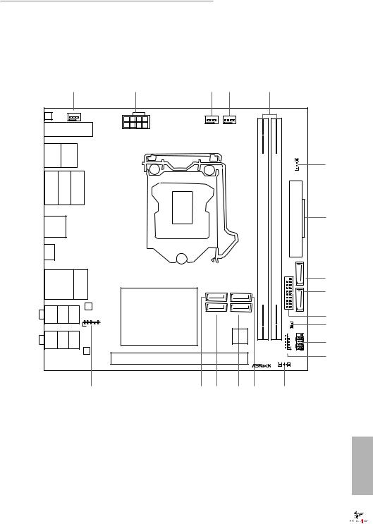
1.3Motherboard Layout Top Side View
|
|
|
|
1 |
|
2 |
|
3 |
4 |
|
|
5 |
|
|
|
|
|
|
|
|
CHA_FAN1 |
|
RoHS |
|
|
|
|
|
|
|
|
|
|
CLR |
|
|
|
|
|
|
|
|
|
|
|
|
|
|
|
|
BTN1 |
|
|
|
|
|
|
|
|
|
|
|
|
|
|
|
|
|
M2_2_WIFI |
|
|
CPU_FAN1 |
CPU_OPT/W_PUMP |
|
|
|
|
|
|
|||||
|
ATX12V1 |
|
|
|
|
|
|
|
|
|
||||||
USB: 2 |
1USBT: Gen1BUS.3 |
|
/Mouse |
Keyboard PS2 |
|
|
|
|
|
|
|
|
RGB_LED1 |
|
6 |
|
|
|
|
|
|
|
|
|
|
|
UltraM.2 |
Gen3x4 |
|
|
1 |
|
|
DP1 |
HDMI1 |
|
OpticalSPDI |
|
|
|
|
(64A1DDR4bit,288-pinmodule) |
(64B1DDR4bit,288-pinmodule) |
ATXPWR1 |
5SATA3 |
|
||||
|
|
|
|
|
RJ-45 |
|
|
|
Z370Gaming-ITX/acPCIe |
|
||||||
|
|
|
|
|
F |
|
|
|
|
|
|
|
|
|
|
|
|
|
|
|
|
|
|
|
|
|
|
|
|
|
|
|
7 |
USB 3.1 Gen1 |
|
|
|
|
|
|
|
|
|
|
|
|
|
|||
T: USB3 |
|
|
|
|
|
|
|
|
|
|
|
|
|
|
||
B: USB4 |
|
|
|
|
|
|
|
|
|
|
|
|
|
|
||
TB 1 |
|
|
|
|
|
|
|
|
|
|
|
|
|
|
|
|
USB 3.1 Gen1 |
|
|
|
|
|
|
|
|
|
|
|
8 |
||||
Top: |
|
|
|
|
|
|
|
|
|
|
|
|||||
T: USB7 |
|
|
|
|
|
|
|
|
|
|
|
|
||||
|
|
|
|
|
|
|
|
|
|
|
|
|
||||
B: USB8 |
|
|
|
|
|
SATA3_3 |
SATA3_2 |
|
|
5 6 |
|
|
9 |
|||
|
|
|
|
|
|
|
|
|
|
|
|
|
USB3 |
|
|
|
|
|
|
|
|
|
|
|
|
|
|
|
|
|
4 |
|
|
|
|
|
|
|
|
LAN |
Intel |
|
SATA3_0 |
SATA3_1 |
|
|
|
|
SATA3_ |
|
CTBASSR |
Bottom: |
REARSP |
Center: |
SIDESP |
Top: |
HD_AUDIO1 |
Z370 |
|
|
|
|
|
|
|
|
10 |
|
|
K |
|
K |
|
|
|
|
|
|
|
CI1 |
|
|
||
|
|
|
|
|
1 |
|
|
|
|
|
|
|
|
|
|
11 |
|
|
|
|
|
|
|
|
|
|
|
|
|
|
1 |
|
|
INMIC |
Bottom: |
FRONT |
Center: |
LINE |
Top: |
|
|
|
|
SUPER |
|
|
|
PWRBTPLEDN |
RESETHDLED |
|
|
|
|
|
I/O |
|
|
|
|
||||||||
|
|
|
|
|
|
|
|
|
|
|
|
|
|
|
|
12 |
|
|
|
|
|
|
AUDIO |
|
|
|
|
|
|
1 |
1 |
|
|
|
|
|
|
|
|
CODEC |
|
|
|
|
|
|
USB1_2 |
PANEL1 |
|
|
|
|
|
|
|
|
|
PCIE1 |
|
|
|
|
|
|
|
|
13 |
|
|
|
|
|
|
|
|
|
|
|
|
SPEAKER1 |
|
|
|
|
|
|
|
|
|
|
|
|
|
|
|
|
|
1 |
|
|
|
|
|
|
|
|
|
19 |
|
18 |
17 |
16 |
15 |
|
14 |
|
|
|
English
7
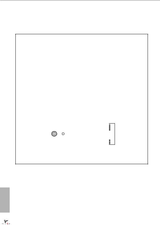
Back Side View

 M2_1
M2_1
English
8

Fatal1ty Z370 Gaming-ITX/ac Series
No. Description
1Chassis Fan Connector (CHA_FAN1)
2ATX 12V Power Connector (ATX12V1)
3CPU Fan Connector (CPU_FAN1)
4CPU Fan Connector (CPU_OPT/W_PUMP)
52 x 288-pin DDR4 DIMM Slots (DDR4_A1, DDR4_B1)
6RGB LED Header (RGB_LED1)
7ATX Power Connector (ATXPWR1)
8SATA Connector (SATA3_5)
9SATA Connector (SATA3_4)
10USB 3.1 Gen1 Header (USB3_5_6)
11Chassis Intrusion Header (CI1)
12System Panel Header (PANEL1)
13USB 2.0 Header (USB1_2)
14Chassis Speaker Header (SPEAKER1)
15SATA3 Connector (SATA3_2)
16SATA3 Connector (SATA3_1)
17SATA3 Connector (SATA3_0)
18SATA3 Connector (SATA3_3)
19Front Panel Audio Header (HD_AUDIO1)
English
9
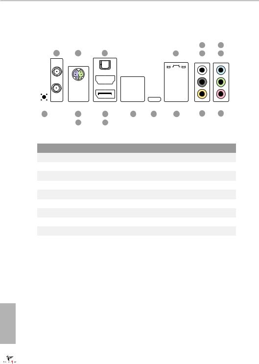
1.4 I/O Panel
|
|
|
|
5 |
7 |
1 |
2 |
3 |
4 |
6 |
8 |
|
|
|
|
|
|
|
|
|
|
|
|
|
|
|
|
|
|
|
|
|
|
|
|
|
|
|
|
|
|
|
|
|
|
|
|
|
|
|
|
|
|
|
|
|
|
|
|
|
|
|
|
|
|
|
|
|
|
|
|
|
|
|
|
|
|
|
|
|
|
|
|
|
|
|
|
|
|
|
|
|
|
|
|
|
|
|
|
|
|
|
|
|
|
|
|
|
|
|
|
|
|
|
|
|
|
|
|
|
|
|
|
|
|
|
|
|
|
|
|
|
|
|
|
|
|
|
|
|
|
|
|
|
|
|
|
|
|
|
|
|
|
|
|
|
|
|
|
|
|
|
|
|
|
|
|
|
|
|
|
|
|
|
|
|
|
|
|
|
|
|
|
|
|
|
|
|
|
|
|
|
|
|
|
|
|
|
|
|
|
|
|
|
|
|
|
|
|
|
|
|
|
|
|
|
|
|
|
|
|
|
|
|
|
|
|
|
|
|
|
|
|
|
|
|
|
|
|
|
|
|
|
|
|
|
|
|
|
|
|
|
|
|
|
|
|
|
|
|
|
|
|
|
|
|
|
|
|
|
|
|
|
|
|
|
|
|
|
|
|
|
|
|
|
|
|
|
|
|
|
|
|
|
|
|
|
|
|
|
|
|
|
|
|
|
|
|
|
|
|
|
|
|
|
|
|
|
|
|
|
|
|
|
|
|
|
|
|
|
|
|
|
|
|
|
|
|
|
|
|
|
|
|
|
|
|
|
|
|
|
|
|
|
|
|
|
|
|
|
|
|
|
|
|
|
|
|
|
|
|
|
|
|
|
|
|
|
|
|
|
|
|
|
|
|
|
|
|
|
|
|
|
|
|
|
|
|
|
|
|
|
|
|
|
|
|
|
|
|
|
|
|
|
|
|
|
|
|
|
|
|
|
18 |
16 |
|
|
|
|
14 |
|
13 |
|
|
12 |
11 |
|
|
|
10 |
9 |
|||||||||||
|
|
17 |
|
|
|
|
15 |
|
|
|
|
|
|
|
|
|
|
|
|
|
|
|
|
|
||||
No. |
Description |
|
|
|
|
|
|
No. |
Description |
|
|
|||||||||||||||||
|
|
|
|
|
|
|
|
|||||||||||||||||||||
1 |
Antenna Ports |
|
|
|
10 |
Central / Bass (Orange) |
|
|||||||||||||||||||||
2 |
PS/2 Mouse/Keyboard Port |
|
11 |
USB 3.1 Gen1 Ports (USB3_78) |
||||||||||||||||||||||||
3 |
Optical SPDIF Out Port |
|
12 |
Intel® ThunderboltTM 3 (TB_1) |
|
|||||||||||||||||||||||
4 |
LAN RJ-45 Port* |
|
|
|
13 |
USB 3.1 Gen1 Ports (USB3_3_4) |
||||||||||||||||||||||
5 |
Side Speaker (Gray) |
|
|
|
14 |
HDMI Port |
|
|
||||||||||||||||||||
6 |
Rear Speaker (Black) |
|
|
|
15 |
DisplayPort 1.2 |
|
|
||||||||||||||||||||
7 |
Line In (Light Blue) |
|
|
|
16 |
Fatal1ty Mouse Port (USB3_1) |
|
|||||||||||||||||||||
8 |
Front Speaker (Lime)** |
|
|
|
17 |
USB 3.1 Gen1 Port (USB3_2) |
|
|||||||||||||||||||||
9 |
Microphone (Pink) |
|
|
|
18 |
Clear CMOS Button |
|
|
||||||||||||||||||||
|
|
|
|
|
|
|
|
|
|
|
|
|
|
|
|
|
|
|
|
|
|
|
|
|
|
|
|
|
English
10
Fatal1ty Z370 Gaming-ITX/ac Series
*There are two LEDs on each LAN port. Please refer to the table below for the LAN port LED indications.
ACT/LINK LED SPEED LED
LAN Port |
|
|
|
|
|
|
Activity / Link LED |
|
Speed LED |
|
|
||
|
|
|
||||
Status |
|
Description |
|
Status |
|
Description |
Off |
|
No Link |
|
Off |
|
10Mbps connection |
|
|
|
||||
Blinking |
|
Data Activity |
|
Orange |
|
100Mbps connection |
On |
|
Link |
|
Green |
|
1Gbps connection |
|
|
|
|
|
|
|
** If you use a 2-channel speaker, please connect the speaker’s plug into “Front Speaker Jack”. See the table below for connection details in accordance with the type of speaker you use.
Audio Output |
Front Speaker |
Rear Speaker |
Central / Bass |
Line In |
Channels |
(No. 8) |
(No. 6) |
(No. 10) |
(No. 7) |
2 |
V |
-- |
-- |
-- |
4 |
V |
V |
-- |
-- |
6 |
V |
V |
V |
-- |
8 |
V |
V |
V |
V |
To enable Multi-Streaming, you need to connect a front panel audio cable to the front panel audio header. After restarting your computer, you will find the “Mixer” tool on your system. Please select “Mixer ToolBox” , click “Enable playback multi-streaming”, and click “ok”. Choose “2CH”, “4CH”, “6CH”, or “8CH” and then you are allowed to select “Realtek HDA Primary output” to use the Rear Speaker, Central/Bass, and Front Speaker, or select “Realtek HDA Audio 2nd output” to use the front panel audio.
English
11
1.5 Intel® WiFi-802.11ac Module 8265 (AC Wave 2 + BLE BT4.2) and ASRock WiFi 2.4/5 GHz Antenna
WiFi-802.11ac + BT Module
This motherboard comes with an exclusive WiFi 802.11 a/b/g/n/ac + BT v4.2 module (pre-installed on the rear I/O panel) that offers support for WiFi 802.11 a/b/ g/n/ac connectivity standards and Bluetooth v4.2. WiFi + BT module is an easy-to- use wireless local area network (WLAN) adapter to support WiFi + BT. Bluetooth v4.2 standard features Smart Ready technology that adds a whole new class of functionality into the mobile devices. BT 4.2 also includes Low Energy Technology and ensures extraordinary low power consumption for PCs. The 2T2R WiFi solution sets a WiFi high speed standard and offers max link rate up to 867Mbps.
* The transmission speed may vary according to the environment.
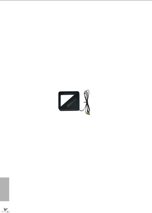
ASRock WiFi 2.4/5 GHz Antenna
English
12

Fatal1ty Z370 Gaming-ITX/ac Series
Chapter 2 Installation
This is a Mini-ITX form factor motherboard. Before you install the motherboard, study the configuration of your chassis to ensure that the motherboard fits into it.
Pre-installation Precautions
Take note of the following precautions before you install motherboard components or change any motherboard settings.
•Make sure to unplug the power cord before installing or removing the motherboard components. Failure to do so may cause physical injuries and damages to motherboard components.
•In order to avoid damage from static electricity to the motherboard’s components, NEVER place your motherboard directly on a carpet. Also remember to use a grounded wrist strap or touch a safety grounded object before you handle the components.
•Hold components by the edges and do not touch the ICs.
•Whenever you uninstall any components, place them on a grounded anti-static pad or in the bag that comes with the components.
•When placing screws to secure the motherboard to the chassis, please do not overtighten the screws! Doing so may damage the motherboard.
English
13
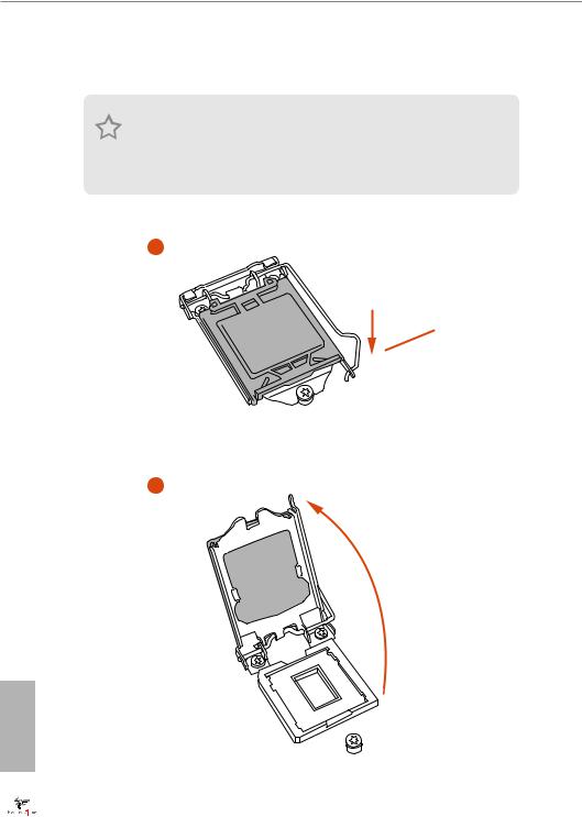
2.1Installing the CPU
1.Before you insert the 1151-Pin CPU into the socket, please check if the PnP cap is on the socket, if the CPU surface is unclean, or if there are any bent pins in the socket. Do not force to insert the CPU into the socket if above situation is found. Otherwise, the CPU will be seriously damaged.
2.Unplug all power cables before installing the CPU.
1
A
 B
B
2
English
14
Fatal1ty Z370 Gaming-ITX/ac Series
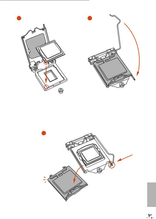
3 |
4 |
5
English
15

Please save and replace the cover if the processor is removed. The cover must be placed if you wish to return the motherboard for after service.
English
16
Fatal1ty Z370 Gaming-ITX/ac Series
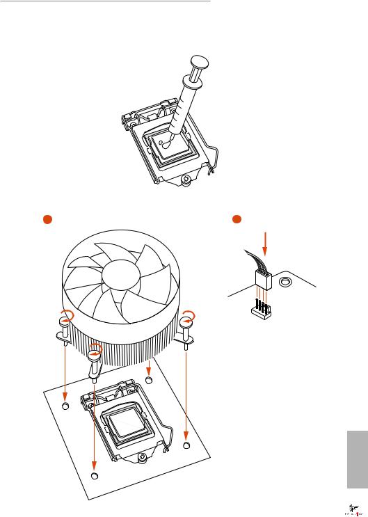
2.2 Installing the CPU Fan and Heatsink
1 |
2 |
N _FA PU C
English
17
2.3 Installing Memory Modules (DIMM)
This motherboard provides two 288-pin DDR4 (Double Data Rate 4) DIMM slots, and supports Dual Channel Memory Technology.
1.For dual channel configuration, you always need to install identical (the same brand, speed, size and chip-type) DDR4 DIMM pairs.
2.It is unable to activate Dual Channel Memory Technology with only one memory module installed.
3.It is not allowed to install a DDR, DDR2 or DDR3 memory module into a DDR4 slot; otherwise, this motherboard and DIMM may be damaged.
The DIMM only fits in one correct orientation. It will cause permanent damage to the motherboard and the DIMM if you force the DIMM into the slot at incorrect orientation.
English
18
 Loading...