


Copyright Notice:
No part of this installation guide may be reproduced, transcribed, transmitted, or translated in any language, in any form or by any means, except duplication of documentation by the purchaser for backup purpose, without written consent of ASRock Inc.
Products and corporate names appearing in this guide may or may not be registered trademarks or copyrights of their respective companies, and are used only for identification or explanation and to the owners’ benefit, without intent to infringe.
Disclaimer:
Specifications and information contained in this guide are furnished for informational use only and subject to change without notice, and should not be constructed as a commitment by ASRock. ASRock assumes no responsibility for any errors or omissions that may appear in this guide.
With respect to the contents of this guide, ASRock does not provide warranty of any kind, either expressed or implied, including but not limited to the implied warranties or conditions of merchantability or fitness for a particular purpose. In no event shall ASRock, its directors, officers, employees, or agents be liable for any indirect, special, incidental, or consequential damages (including damages for loss of profits, loss of business, loss of data, interruption of business and the like), even if ASRock has been advised of the possibility of such damages arising from any defect or error in the guide or product.
This device complies with Part 15 of the FCC Rules. Operation is subject to the following two conditions:
(1)this device may not cause harmful interference, and
(2)this device must accept any interference received, including interference that may cause undesired operation.
CALIFORNIA, USA ONLY
The Lithium battery adopted on this motherboard contains Perchlorate, a toxic substance controlled in Perchlorate Best Management Practices (BMP) regulations passed by the California Legislature. When you discard the Lithium battery in California, USA, please follow the related regulations in advance.
“Perchlorate Material-special handling may apply, see www.dtsc.ca.gov/hazardouswaste/perchlorate”
ASRock Website: http://www.asrock.com
Published April 2008
Copyright©2008 ASRock INC. All rights reserved.
1
English
ASRock K10N78hSLI-GLAN Motherboard
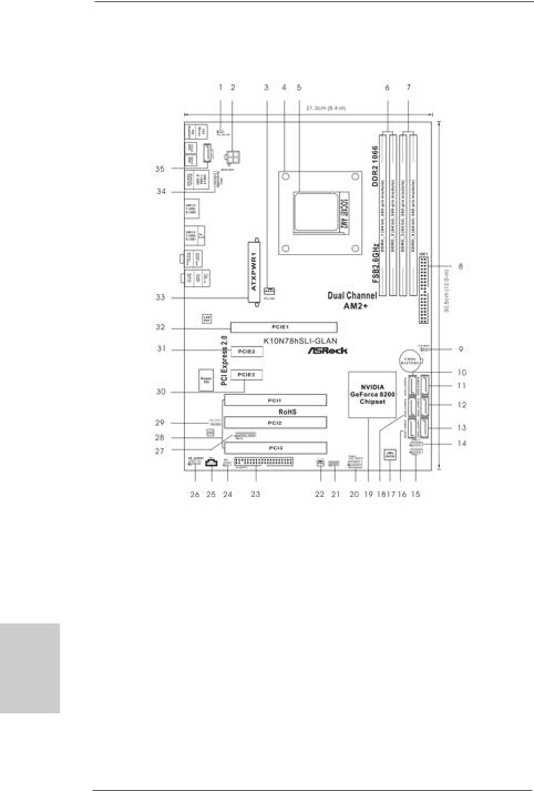
Motherboard Layout
English
2
1 |
PS2_USB_PW1 Jumper |
18 |
SATAII Connector (SATAII_3 (PORT2)) |
|
2 |
ATX 12V Power Connector (ATX12V1) |
19 |
NVIDIA GeForce 8200 |
Chipset |
3 |
CPU Fan Connector (CPU_FAN1) |
20 |
System Panel Header |
(PANEL1) |
4 |
CPU Heatsink Retention Module |
21 |
Chassis Speaker Header (SPEAKER 1) |
|
5 |
AM2 940-Pin CPU Socket |
22 |
Chassis Fan Connector (CHA_FAN1) |
|
6 |
2 x 240-pin DDR2 DIMM Slots |
23 |
Floppy Connector (FLOPPY1) |
|
|
(Dual Channel A: DDRII_1, DDRII_2; Yellow) |
24 |
DeskExpress Hot Plug Detection Header |
|
7 |
2 x 240-pin DDR2 DIMM Slots |
|
(IR1) |
|
|
(Dual Channel B: DDRII_3, DDRII_4; Orange) |
25 |
Internal Audio Connector: CD1 (Black) |
|
8 |
Primary IDE Connector (IDE1, Blue) |
26 |
Front Panel Audio Header (HD_AUDIO1) |
|
9 |
Clear CMOS Jumper (CLRCMOS1) |
27 |
WiFi/E Header (WIFI/E) |
|
10 |
SATAII Connector (SATAII_5 (PORT4)) |
28 |
PCI Slots (PCI1- 3) |
|
11 |
SATAII Connector (SATAII_6 (PORT5)) |
29 |
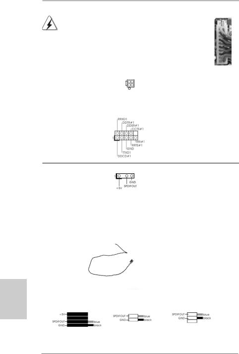
HDMI_SPDIF Header (HDMI_SPDIF1) |
|
12 |
SATAII Connector (SATAII_4 (PORT3)) |
30 |
PCI Express x1 Slot (PCIE3, White) |
|
13 |
SATAII Connector (SATAII_2 (PORT1)) |
31 |
PCI Express x1 Slot |
(PCIE2, White) |
14 |
USB 2.0 Header (USB8_9, Blue) |
32 |
PCI Express x16 Slot (PCIE1, Green) |
|
15 |
USB 2.0 Header (USB6_7, Blue) |
33 |
ATX Power Connector (ATXPWR1) |
|
16 |
SATAII Connector (SATAII_1 (PORT0)) |
34 |
COM Port Header (COM1) |
|
17 |
SPI BIOS Chip |
35 |
eSATAII Connector (eSATAII_TOP) |
|
ASRock K10N78hSLI-GLAN Motherboard
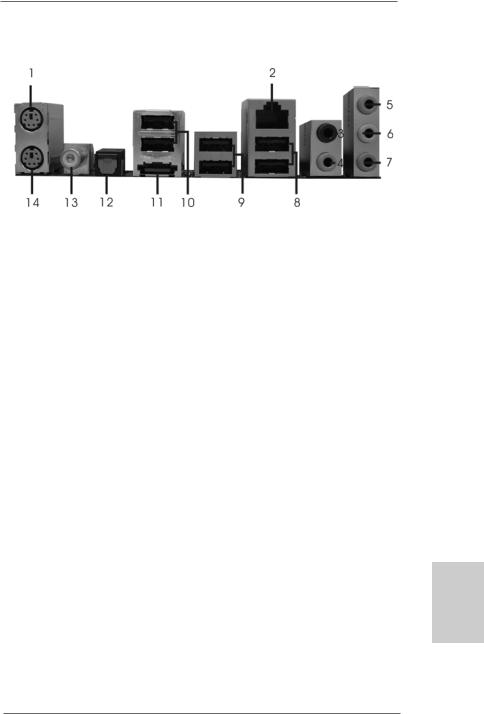
ASRock eSATAII_SPDIF I/O
1 |
PS/2 |
Mouse Port (Green) |
8 |
USB 2.0 Ports |
(USB01) |
|
2 |
LAN RJ-45 Port |
9 |
USB 2.0 Ports (USB23) |
|||
3 |
Rear |
Speaker |
(Black) |
10 |
USB 2.0 Ports |
(USB45) |
4 |
Central / Bass |
(Orange) |
11 |
eSATAII Port |
|
|
5 |
Line |
In (Light Blue) |
12 Optical SPDIF Out Port |
|||
*6 |
Front |
Speaker |
(Lime) |
13 |
Coaxial SPDIF Out Port |
|
7 |
Microphone (Pink) |
14 |
PS/2 Keyboard |
Port (Purple) |
||
*If you use 2-channel speaker, please connect the speaker’s plug into “Front Speaker Jack”. See the table below for connection details in accordance with the type of speaker you use.
TABLE for Audio Output Connection
Audio Output Channels |
Front Speaker |
Rear Speaker |
Central / Bass |
|
(No. 6) |
(No. 3) |
(No. 4) |
2 |
V |
-- |
-- |
4 |
V |
V |
-- |
6 |
V |
V |
V |
*To enable Multi-Streaming function, you need to connect a front panel audio cable to the front panel audio header. Please refer to below steps for the software setting of Multi-Streaming.
For Windows® XP:
After restarting your computer, you will find “Mixer” tool on your system. Please select “Mixer ToolBox”  , click “Enable playback multi-streaming”, and click “ok”. Choose “2CH” or
“4CH” and then you are allowed to select “Realtek HDA Primary output” to use Rear Speaker and Front Speaker, or select “Realtek HDA Audio 2nd output” to use front panel audio. Then reboot your system.
For Windows® VistaTM:
After restarting your computer, please double-click “Realtek HD Audio Manager” on the system tray. Set “Speaker Configuration” to “5.1 Speaker”. Click “Device advanced settings”, choose “Make front and rear output devices playbacks two different audio streams simultaneously”, and click “ok”. Then reboot your system.
3
English
ASRock K10N78hSLI-GLAN Motherboard
1. Introduction
Thank you for purchasing ASRock K10N78hSLI-GLAN motherboard, a reliable motherboard produced under ASRock’s consistently stringent quality control. It delivers excellent performance with robust design conforming to ASRock’s commitment to quality and endurance.
This Quick Installation Guide contains introduction of the motherboard and step-by- step installation guide. More detailed information of the motherboard can be found in the user manual presented in the Support CD.
Because the motherboard specifications and the BIOS software might be updated, the content of this manual will be subject to change without notice. In case any modifications of this manual occur, the updated version will be available on ASRock website without further notice. You may find the latest VGA cards and CPU support lists on ASRock website as well. ASRock website http://www.asrock.com
If you require technical support related to this motherboard, please visit our website for specific information about the model you are using. www.asrock.com/support/index.asp
1.1 Package Contents
ASRock K10N78hSLI-GLAN Motherboard
(ATX Form Factor: 12.0-in x 8.4-in, 30.5 cm x 21.3 cm) ASRock K10N78hSLI-GLAN Quick Installation Guide ASRock K10N78hSLI-GLAN Support CD
One 80-conductor Ultra ATA 66/100/133 IDE Ribbon Cable One Ribbon Cable for a 3.5-in Floppy Drive
Two Serial ATA (SATA) Data Cables (Optional)
One Serial ATA (SATA) HDD Power Cable (Optional) One HDMI_SPDIF Cable (Optional)
One “ASRock eSATAII_SPDIF I/O” I/O Panel Shield
hsilgnE
4
ASRock K10N78hSLI-GLAN Motherboard

1.2 Specifications
Platform |
- ATX Form Factor: 12.0-in x 8.4-in, 30.5 cm x 21.3 cm |
CPU |
- Support for Socket AM2+ / AM2 processors: AMD PhenomTM |
|
FX / Phenom / Athlon 64 FX / Athlon 64 X2 Dual-Core / Athlon |
|
X2 Dual-Core / Athlon 64 / Sempron processor |
|
- AMD LIVE!TM Ready |
|
- Supports AMD’s Cool ‘n’ QuietTM Technology |
|
- FSB 2600 MHz (5.2 GT/s) (see CAUTION 1) |
|
- Supports Untied Overclocking Technology (see CAUTION 2) |
|
- Supports Hyper-Transport 3.0 (HT 3.0) Technology |
Chipset |
- NVIDIA® GeForce 8200 |
Memory |
- Dual Channel DDR2 Memory Technology (see CAUTION 3) |
|
- 4 x DDR2 DIMM slots |
|
- SupportDDR2 1066/800/667/533 non-ECC, un-buffered memory |
|
(see CAUTION 4) |
|
- Max. capacity of system memory: 8GB (see CAUTION 5) |
Expansion Slot |
- 1 x PCI Express 2.0 x16 slot (green @ x16 mode) |
|
- 2 x PCI Express x1 slots |
|
- 3 x PCI slots |
|
- Supports NVIDIA® Hybrid SLITM Geforce® Boost feature |
|
(see CAUTION 6) |
Audio |
- 5.1 CH Windows® VistaTM Premium Level HD Audio |
|
(ALC662 Audio Codec) |
LAN |
- Gigabit LAN 10/100/1000 Mb/s |
|
- Giga PHY Realtek RTL8211B |
|
- Supports Wake-On-LAN |
Rear Panel I/O |
ASRock eSATAII_SPDIF I/O |
|
- 1 x PS/2 Mouse Port |
|
- 1 x PS/2 Keyboard Port |
|
- 1 x Coaxial SPDIF Out Port |
|
- 1 x Optical SPDIF Out Port |
|
- 6 x Ready-to-Use USB 2.0 Ports |
|
- 1 x eSATAII Port |
|
- 1 x RJ-45 LAN Port |
|
- HDAudio Jack: Rear Speaker/Central/Bass/Line in/Front |
|
Speaker/Microphone (see CAUTION 7) |
Connector |
- 6 x SATAII 3.0Gb/s connectors, support RAID (RAID 0, RAID 1, |
|
RAID 0+1, JBOD and RAID 5), NCQ, AHCI and “Hot Plug” |
|
functions (see CAUTION 8) |
English
5
ASRock K10N78hSLI-GLAN Motherboard

|
|
|
- 1 x eSATAII 3.0Gb/s connector (shared with 1 SATAII |
|
|
|
|
connector) (see CAUTION 9) |
|
|
|
|
- 1 x ATA133 IDE connector (supports 2 x IDE devices) |
|
|
|
|
- 1 x Floppy connector |
|
|
|
|
- 1 x DeskExpress Hot Plug Detection header |
|
|
|
|
- 1 x COM port header |
|
|
|
|
- 1 x HDMI_SPDIF header |
|
|
|
|
- CPU/Chassis FAN connector |
|
|
|
|
- 24 pin ATX power connector |
|
|
|
|
- 4 pin 12V power connector |
|
|
|
|
- CD in header |
|
|
|
|
- Front panel audio connector |
|
|
|
|
- 2 x USB 2.0 headers (support 4 USB 2.0 ports) |
|
|
|
|
(see CAUTION 10) |
|
|
|
|
- 1 x WiFi/E header (see CAUTION 11) |
|
|
|
BIOS Feature |
- 4Mb AMI BIOS |
|
|
|
|
- AMI Legal BIOS |
|
|
|
|
- Supports “Plug and Play” |
|
|
|
|
- ACPI 1.1 Compliance Wake Up Events |
|
|
|
|
- Supports jumperfree |
|
|
|
|
- AMBIOS 2.3.1 Support |
|
|
|
|
- CPU, DRAM, Chipset Core, HTT Voltage Multi-adjustment |
|
|
|
Support CD |
- Drivers, Utilities, AntiVirus Software (Trial Version) |
|
|
|
Unique Feature |
- ASRock OC Tuner (see CAUTION 12) |
|
|
|
|
- Intelligent Energy Saver (see CAUTION 13) |
|
|
|
|
- Hybrid Booster: |
|
|
|
|
- CPU Frequency Stepless Control (see CAUTION 14) |
|
|
|
|
- ASRock U-COP (see CAUTION 15) |
|
|
|
|
- Boot Failure Guard (B.F.G.) |
|
|
|
|
- ASRock AM2 Boost: ASRock Patented Technology to boost |
|
|
|
|
memory performance up to 12.5% (see CAUTION 16) |
|
|
|
Hardware |
- CPU Temperature Sensing |
|
E |
||||
|
Monitor |
- Chassis Temperature Sensing |
||
lgn |
|
|||
|
|
- CPU Fan Tachometer |
||
si |
|
|
- Chassis Fan Tachometer |
|
h |
|
|
||
|
|
- CPU Quiet Fan |
||
|
|
|
||
|
|
|
- Voltage Monitoring: +12V, +5V, +3.3V, CPU Vcore |
|
|
|
|
||
|
|
OS |
- Microsoft® Windows® XP / XP Media Center / XP 64-bit / VistaTM |
|
|
|
|
/ VistaTM 64-bit compliant |
|
|
|
Certifications |
- FCC, CE, WHQL |
* For detailed product information, please visit our website: http://www.asrock.com
6
ASRock K10N78hSLI-GLAN Motherboard

WARNING
Please realize that there is a certain risk involved with overclocking, including adjusting the setting in the BIOS, applying Untied Overclocking Technology, or using the third-party overclocking tools. Overclocking may affect your system stability, or even cause damage to the components and devices of your system. It should be done at your own risk and expense. We are not responsible for possible damage caused by overclocking.
CAUTION!
1.If you install AM2 CPU on this motherbord, the system bus speed will be HT1.0 (2000 MT/s). If you install AM2+ CPU on this motherbord, the system
bus speed will be HT3.0 (up to 5200 MT/s), and the HT Link frequency depends on the ability of the AM2+ CPU you adopt. Please refer to the CPU support list on our website for more information.
ASRock website http://www.asrock.com
2.This motherboard supports Untied Overclocking Technology. Please read “Untied Overclocking Technology” on page 28 for details.
3.This motherboard supports Dual Channel Memory Technology. Before you implement Dual Channel Memory Technology, make sure to read the installation guide of memory modules on page 12 for proper installation.
4.Whether 1066MHz memory speed is supported depends on the AM2+ CPU you adopt. If you want to adopt DDR2 1066 memory module on this motherboard, please refer to the memory support list on our website for the compatible memory modules.
ASRock website http://www.asrock.com
5.Due to the operating system limitation, the actual memory size may be less than 4GB for the reservation for system usage under Windows® XP and Windows® VistaTM. For Windows® XP 64-bit and Windows® VistaTM 64-bit with 64-bit CPU, there is no such limitation.
6.Hybrid SLITM feature should depend on the driver from NVIDIA® and it may be updated in the future. As long as we have the latest Hybrid SLITM driver, we will update it to our website. Please visit our website for the updated Hybrid SLITM driver in the future. For the operation procedures, please refer to “Hybrid SLITM Operation Guide” on page 15.
7.For microphone input, this motherboard supports both stereo and mono modes. For audio output, this motherboard supports 2-channel, 4-channel and 6-channel modes. Please check the table on page 3 for proper connection.
8.Before installing SATAII hard disk to SATAII connector, please read the “SATAII Hard Disk Setup Guide” on page 30 of “User Manual” in the support CD to adjust your SATAII hard disk drive to SATAII mode. You can also connect SATA hard disk to SATAII connector directly.
9.This motherboard supports eSATAII interface, the external SATAII specification. Please read “eSATAII Interface Introduction” on page 23 for details about eSATAII and eSATAII installation procedures.
English
7
ASRock K10N78hSLI-GLAN Motherboard

hsilgnE
8
10.Power Management for USB 2.0 works fine under Microsoft® Windows® VistaTM 64-bit / VistaTM / XP 64-bit / XP SP1 or SP2.
11.WiFi/E header supports WiFi+AP function with ASRock WiFi-802.11g or WiFi-802.11n module, an easy-to-use wireless local area network (WLAN) adapter. It allows you to create a wireless environment and enjoy the convenience of wireless network connectivity. Please visit our website for the availability of ASRock WiFi-802.11g or WiFi-802.11n
module. ASRock website http://www.asrock.com
12.It is a user-friendly ASRock overclocking tool which allows you to surveil your system by hardware monitor function and overclock your hardware devices to get the best system performance under Windows® environment. Please visit our website for the operation procedures of ASRock OC Tuner. ASRock website: http://www.asrock.com
13.Featuring an advanced proprietary hardware and software design, Intelligent Energy Saver is a revolutionary technology that delivers unparalleled power savings. The voltage regulator can reduce the number of output phases to improve efficiency when the CPU cores are idle. In other words, it is able to provide exceptional power saving and improve power efficiency without sacrificing computing performance. To use Intelligent Energy Saver function, please enable Cool ‘n’ Quiet option in the BIOS setup in advance. Please visit our website for the operation procedures of Intelligent Energy Saver.
ASRock website: http://www.asrock.com
14.Although this motherboard offers stepless control, it is not recommended to perform over-clocking. Frequencies other than the recommended CPU bus frequencies may cause the instability of the system or damage the CPU.
15.While CPU overheat is detected, the system will automatically shutdown. Before you resume the system, please check if the CPU fan on the motherboard functions properly and unplug the power cord, then plug it back again. To improve heat dissipation, remember to spray thermal grease between the CPU and the heatsink when you install the PC system.
16.This motherboard supports ASRock AM2 Boost overclocking technology for AM2 CPU. If you enable this function in the BIOS setup, the memory performance will improve up to 12.5%, but the effect still depends on the AM2 CPU you adopt. Enabling this function will overclock the chipset/CPU reference clock. However, we can not guarantee the system stability for all CPU/DRAM configurations. If your system is unstable after AM2 Boost function is enabled, it may not be applicative to your system. You may choose to disable this function for keeping the stability of your system.
ASRock K10N78hSLI-GLAN Motherboard

1.3 Minimum Hardware Requirement Table for Windows® VistaTM Premium 2008 and Basic Logo
For system integrators and users who purchase this motherboard and
plan to submit Windows® VistaTM Premium 2008 and Basic logo, please follow below table for minimum hardware requirement.
CPU |
Sempron 2800+ |
Memory |
1GB system memory (Premium) |
|
512MB system memory (Basic) |
VGA |
DX10 with WDDM Driver |
|
with 128bit VGA memory (Premium) |
|
with 64bit VGA memory (Basic) |
*After June 1, 2008, all Windows® VistaTM systems are required to meet above minimum hardware requirements in order to qualify for Windows® VistaTM Premium 2008 logo.
English
9
ASRock K10N78hSLI-GLAN Motherboard
2. Installation
This is an ATX form factor (12.0-in x 8.4-in, 30.5 cm x 21.3 cm) motherboard.
Before you install the motherboard, study the configuration of your chassis to ensure that the motherboard fits into it.
Pre-installation Precautions
Take note of the following precautions before you install motherboard components or change any motherboard settings.
Before you install or remove any component, ensure that the power is switched off or the power cord is detached from the power supply. Failure to do so may cause severe damage to the motherboard, peripherals, and/or components.
1.Unplug the power cord from the wall socket before touching any component.
2.To avoid damaging the motherboard components due to static electricity, NEVER place your motherboard directly on the carpet or the like. Also remember to use a grounded wrist strap or touch a safety grounded object before you handle components.
3.Hold components by the edges and do not touch the ICs.
4.Whenever you uninstall any component, place it on a grounded antistatic pad or in the bag that comes with the component.
5.When placing screws into the screw holes to secure the motherboard to the chassis, please do not over-tighten the screws! Doing so may damage the motherboard.
hsilgnE
1 0
ASRock K10N78hSLI-GLAN Motherboard
2.1CPU Installation
Step 1. Unlock the socket by lifting the lever up to a 90o angle.
Step 2. Position the CPU directly above the socket such that the CPU corner with the golden triangle matches the socket corner with a small triangle.
Step 3. Carefully insert the CPU into the socket until it fits in place.
The CPU fits only in one correct orientation. DO NOT force the CPU into the socket to avoid bending of the pins.
Step 4. When the CPU is in place, press it firmly on the socket while you push down the socket lever to secure the CPU. The lever clicks on the side tab to indicate that it is locked.
Lever 90°Up |
|
|
|
CPU Golden Triangle |
|
|
SocketCorner |
|
|
Small Triangle |
|
STEP 1: |
STEP 2 / STEP 3: |
STEP 4: |
Lift Up The Socket Lever |
Match The CPU Golden Triangle |
Push Down And Lock |
|
To The Socket Corner Small |
The Socket Lever |
|
Triangle |
|
2.2 Installation of CPU Fan and Heatsink
After you install the CPU into this motherboard, it is necessary to install a larger heatsink and cooling fan to dissipate heat. You also need to spray thermal grease between the CPU and the heatsink to improve heat dissipation. Make sure that the CPU and the heatsink are securely fastened and in good contact with each other. Then connect the CPU fan to the CPU FAN connector (CPU_FAN1, see Page 2, No. 3). For proper installation, please kindly refer to the instruction manuals of the CPU fan and the heatsink.
English
1 1
ASRock K10N78hSLI-GLAN Motherboard
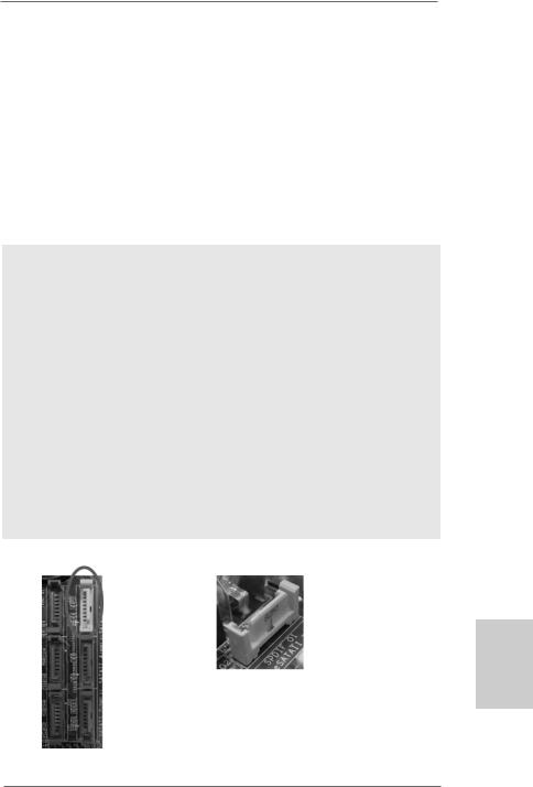
2.3 Installation of Memory Modules (DIMM)
This motherboard provides four 240-pin DDR2 (Double Data Rate 2) DIMM slots, and supports Dual Channel Memory Technology. For dual channel configuration, you always need to install identical (the same brand, speed, size and chip-type) DDR2 DIMM pair in the slots of the same color. In other words, you have to install identical DDR2 DIMM pair in Dual Channel A (DDRII_1 and DDRII_2; Yellow slots; see p.2 No.6) or identical DDR2 DIMM pair in Dual Channel B (DDRII_3 and DDRII_4; Orange slots; see p.2 No.7), so that Dual Channel Memory Technology can be activated. This motherboard also allows you to install four DDR2 DIMMs for dual channel configuration, and please install identical DDR2 DIMMs in all four slots. You may refer to the Dual Channel Memory Configuration Table below.
hsilgnE
1 2
Dual Channel Memory Configurations
|
DDRII_1 |
DDRII_2 |
DDRII_3 |
DDRII_4 |
|
(Yellow Slot) |
(Yellow Slot) |
(Orange Slot) |
(Orange Slot) |
(1) |
Populated |
Populated |
- |
- |
(2) |
- |
- |
Populated |
Populated |
(3)* |
Populated |
Populated |
Populated |
Populated |
|
|
|
|
|
*For the configuration (3), please install identical DDR2 DIMMs in all four slots.
1.If you want to install two memory modules, for optimal compatibility and reliability, it is recommended to install them in the slots of the same color. In other words, install them either in the set of yellow slots (DDRII_1 and DDRII_2), or in the set of orange slots (DDRII_3 and DDRII_4).
2.If only one memory module or three memory modules are installed in the DDR2 DIMM slots on this motherboard, it is unable to activate the Dual Channel Memory Technology.
3.If a pair of memory modules is NOT installed in the same Dual Channel, for example, installing a pair of memory modules in DDRII_1 and DDRII_3, it is unable to activate the Dual Channel Memory Technology .
4.It is not allowed to install a DDR memory module into DDR2 slot; otherwise, this motherboard and DIMM may be damaged.
ASRock K10N78hSLI-GLAN Motherboard
Installing a DIMM
Please make sure to disconnect power supply before adding or removing DIMMs or the system components.
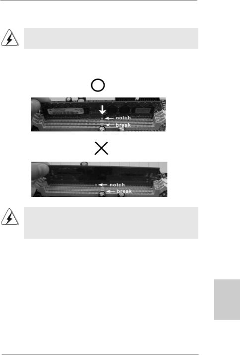
Step 1. Unlock a DIMM slot by pressing the retaining clips outward.
Step 2. Align a DIMM on the slot such that the notch on the DIMM matches the break on the slot.
The DIMM only fits in one correct orientation. It will cause permanent damage to the motherboard and the DIMM if you force the DIMM into the slot at incorrect orientation.
Step 3. Firmly insert the DIMM into the slot until the retaining clips at both ends fully snap back in place and the DIMM is properly seated.
English
1 3
ASRock K10N78hSLI-GLAN Motherboard
2.4 Expansion Slots (PCI and PCI Express Slots)
There are 3 PCI slots and 3 PCI Express slots on this motherboard.
PCI slots: PCI slots are used to install expansion cards that have the 32-bit PCI interface.
PCIE slots: PCIE1 (PCIE x16 slot; Green) is used for PCI Express cards with x16 lane width graphics cards.
PCIE2 / PCIE3 (PCIE x1 slot; White) is used for PCI Express cards with x1 lane width cards, such as Gigabit LAN card, SATA2 card and ASRock PCIE_DE card.
If you want to use ASRock DeskExpress function on this motherboard, please install ASRock PCIE_DE card on PCIE3 slot.
Installing an expansion card
Step 1. Before installing the expansion card, please make sure that the power supply is switched off or the power cord is unplugged. Please read the documentation of the expansion card and make necessary hardware settings for the card before you start the installation.
Step 2. Remove the system unit cover (if your motherboard is already installed in a chassis).
Step 3. Remove the bracket facing the slot that you intend to use. Keep the screws for later use.
Step 4. Align the card connector with the slot and press firmly until the card is completely seated on the slot.
Step 5. Fasten the card to the chassis with screws. Step 6. Replace the system cover.
hsilgnE
1 4
ASRock K10N78hSLI-GLAN Motherboard

2.5 Hybrid SLITM Operation Guide
This motherboard supports NVIDIA® Hybrid SLITM feature. Hybrid SLITM technology, based on NVIDIA®’ s industry-leading SLITM technology, delivers multi-GPU (graphics processing unit) benefits when an NVIDIA® motherboard GPU is combined with an NVIDIA® discrete GPU. Hybrid SLITM technology today includes two primary features: GeForce® Boost and HybridPowerTM. This motherboard is compatible with GeForce® Boost feature in Hybrid SLITM, which can increase graphics performance. Currently, NVIDIA® Hybrid SLITM Technology is only supported with Windows® VistaTM OS, and is not available with other OS. Please visit our website for the driver update in the future.
GeForce® Boost
GeForce® Boost turbocharges the performance of NVIDIA® discrete GPU when combined with NVIDIA® motherboard GPU. When GeForce® Boost is enabled, the motherboard GPU and the discrete GPU share the rendering load by rendering different frames of an image. Installing NVIDIA® Hybrid SLITM-enabled graphics card into NVIDIA® Hybrid SLITM-enabled motherboard allows you to enjoy additive performance.
Minimum System Configuration for Hybrid SLITM
For best Hybrid SLITM benefits, the following minimum system configuration is recommended. Please refer to below table for the minimum system configuration for GeForce® Boost mode.
CPU |
AMD Phenom CPU |
Memory |
Dual Channel DDR2 800, 1024MB x 2 |
|
256MB or 512MB shared memory for motherboard GPU |
Suggested OS |
Windows® VistaTM or Windows® VistaTM 64 |
Supported PCI Express Card for Hybrid SLITM
GeForce® Boost feature is supported only with certain set of discrete GPUs. Please refer to our website for the graphics cards update in the future.
Vendor |
Chipset |
Model |
Driver |
|
|
NVIDIA |
GeForce 8400GS |
Gigabyte GV-NX84G256H |
174.91 |
|
English |
|
GeForce 8400GS |
Foxconn FV-N84SM2DT |
174.91 |
|
|
|
|
|
|||
|
GeForce 8400GS |
Leadtek WinFast PX8400 GS TDH |
174.91 |
|
|
|
GeForce 8500GT |
Gigabyte GV-NX85T256H |
174.91 |
|
|
|
|
|
|
|
|
1 5
ASRock K10N78hSLI-GLAN Motherboard
Enjoy the benefit of NVIDIA® Hybrid SLITM
To enjoy Hybrid SLITM feature, please refer to below installation and setup procedures.
Step 1. Install one compatible PCI Express graphics card to PCIE1 slot (green). For the proper installation procedures, please refer to section “Expansion Slots”.
Step 2. Connect the monitor cable to the correspondent connector on the PCI Express graphics card on PCIE1 slot.
Step 3. Boot your system. Press <F2> to enter BIOS setup. Enter “Advanced” screen, and enter “Chipset Settings”. Then set the option “Hybrid SLI” to [Auto] or [Chipset Default].
Step 4. Boot into OS. Install Hybrid SLITM driver from our support CD to your system. Hybrid SLITM driver is in the following path of ASRock support CD:
(There are two ASRock support CD in the motherboard gift box pack, please choose the one for Windows® VistaTM / VistaTM 64-bit.)
..\Drivers\Hybrid SLI driver\nVIDIA\Vista(174.91) (For Windows® VistaTM
OS)
..\Drivers\Hybrid SLI driver\nVIDIA\Vista64(174.91) (For Windows® VistaTM 64-bit OS)
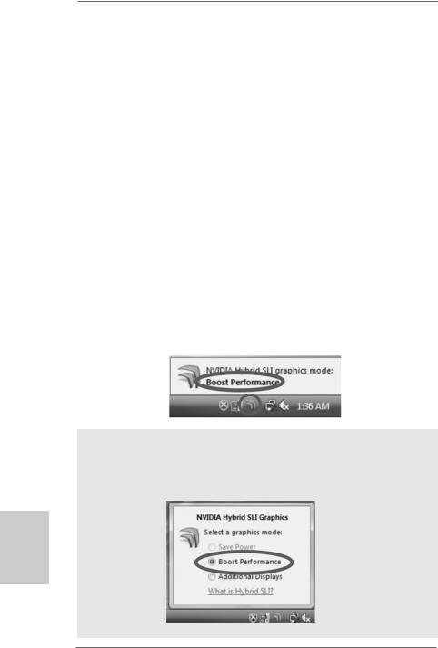
Step 5. Restart your computer. Then you will find the Hybrid icon on your Windows® taskbar.
Step 6. The default setting is GeForce® Boost mode (Boost Performance). You do not need to adjust the setup anymore.
NOTE
If you click the Hybrid icon on the Windows® task bar, you are allowed to select your required Hybrid SLITM mode. However, since this motherboard only support GeForce® Boost mode (Boost Performance), please do not select the options (“Save Power” and “Additional Displays”) other than “Boost Performance”.
hsilgnE
1 6
ASRock K10N78hSLI-GLAN Motherboard
2.6 Jumpers Setup
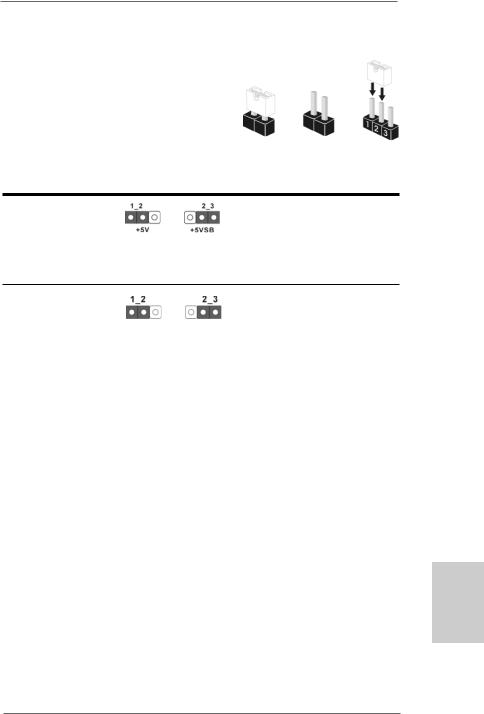
The illustration shows how jumpers are setup. When the jumper cap is placed on pins, the jumper is “Short”. If no jumper cap is placed on pins, the jumper is “Open”. The illustration shows a 3-pin jumper whose pin1 and
pin2 are “Short” when jumper cap is placed on Short Open these 2 pins.
Setting
Short pin2, pin3 to enable +5VSB (standby) for PS/2 or
USB wake up events. Note: To select +5VSB, it requires 2 Amp and higher standby current provided by
power supply.
Clear CMOS Jumper
(CLRCMOS1)
(see p.2, No. 9) Default Clear CMOS
Note: CLRCMOS1 allows you to clear the data in CMOS. The data in CMOS includes system setup information such as system password, date, time, and system setup parameters. To clear and reset the system parameters to default setup, please turn off the computer and unplug the power cord from the power supply. After waiting for 15 seconds, use a jumper cap to short pin2 and pin3 on CLRCMOS1 for 5 seconds. However, please do not clear the CMOS right after you update the BIOS. If you need to clear the CMOS when you just finish updating the BIOS, you must boot up the system first, and then shut it down before you do the clearCMOS action.
English
1 7
ASRock K10N78hSLI-GLAN Motherboard
hsilgnE
2.7 Onboard Headers and Connectors
Onboard headers and connectors are NOT jumpers. Do NOT place jumper caps over these headers and connectors. Placing jumper caps over the headers and connectors will cause permanent damage of the motherboard!
•
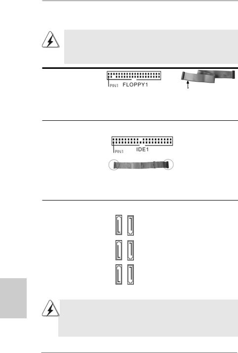
Floppy Connector
(33-pin FLOPPY1)
(see p.2, No. 23)
the red-striped side to Pin1
Note: Make sure the red-striped side of the cable is plugged into Pin1 side of the connector.
Primary IDE connector (Blue)
(39-pin IDE1, see p.2, No. 8)
connect the blue end |
connect the black end |
|
to the motherboard |
to the IDE devices |
|
80-conductor ATA 66/100/133 cable |
|
|
Note: Please refer to the instruction of your IDE device vendor |
for the details. |
|
Serial ATA II Connectors
(SATAII_1 (PORT0):
see p.2, No. 16)
(SATAII_2 (PORT1):
see p.2, No. 13)
(SATAII_3 (PORT2):
see p.2, No. 18) (SATAII_4 (PORT3): see p.2, No. 12) (SATAII_5 (PORT4): see p.2, No. 10) (SATAII_6 (PORT5): see p.2, No. 11)
SATAII 5 |
(PORT4) |
SATAII 6 |
(PORT5) |
SATAII 3 |
(PORT2) |
SATAII 4 |
(PORT3) |
SATAII 1 |
(PORT0) |
SATAII 2 |
(PORT1) |
These six Serial ATAII (SATAII) connectors support SATA data cables for internal storage devices. The current SATAII interface allows up to 3.0 Gb/s data transfer rate.
SATAII_6 (PORT5) connector can be used for internal storage device or be connected to eSATAII connector to support eSATAII device. Please read “eSATAII Interface Introduction” on page 23 for details about eSATAII and eSATAII installation procedures.
1 8
ASRock K10N78hSLI-GLAN Motherboard
eSATAII Connector
(eSATAII_TOP: see p.2, No. 35) TOP  _eSATAII
Serial ATA (SATA) Data Cable
(Optional)
Serial ATA (SATA)
Power Cable
(Optional) |
connect to the SATA |
|
HDD power connector |
connect to the power supply
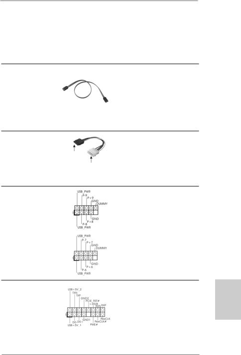
USB 2.0 Headers
(9-pin USB8_9)
(see p.2 No. 14)
(9-pin USB6_7)
(see p.2 No. 15)
WiFi/E Header
(15-pin WIFI/E)
(see p.2 No. 27)
This eSATAII connector supports SATA data cable for external SATAII function. The current eSATAII interface allows up to 3.0 Gb/s data transfer rate.
Either end of the SATA data cable can be connected to the SATA / SATAII hard disk or the SATAII connector on this motherboard. You can also use the SATA data cable to connect SATAII_6
(PORT5) connector and eSATAII connector.
Please connect the black end of SATA power cable to the power connector on each drive. Then connect the white end of SATA power cable to the power connector of the power supply.
Besides six default USB 2.0 ports on the I/O panel, there are two USB 2.0 headers on this motherboard. Each USB 2.0 header can support two USB 2.0 ports.
This header supports WiFi+AP function with ASRock WiFi-802.11g or WiFi-802.11n module, an easy-to-use wireless local area network (WLAN) adapter. It allows you to create a wirelessenvironmentandenjoythe convenience of wireless network
connectivity.
1 9
English
ASRock K10N78hSLI-GLAN Motherboard
If you don’t plan to use WiFi+AP functin on this motherboard, this header can be used as a 4-Pin USB 2.0 header to support one USB 2.0 port. To connect the 4-Pin USB device cable to this header, please refer to
this picture for proper installation.
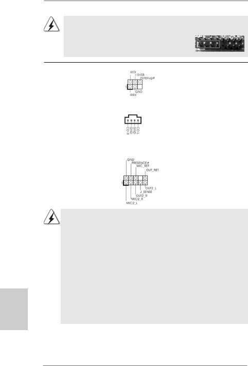
DeskExpress Hot Plug Detection |
|
This header supports the Hot |
|
Header |
|
Plug detection function for |
|
(5-pin IR1) |
|
ASRock DeskExpress. |
|
(see p.2 No. 24) |
|
|
|
|
|
|
|
Internal Audio Connectors |
|
This connector allows you |
|
(4-pin CD1) |
CD1 |
to receive stereo audio input |
|
(CD1: see p.2, No. 25) |
from sound sources such as |
||
|
|||
|
|
a CD-ROM, DVD-ROM, TV |
|
|
|
tuner card, or MPEG card. |
|
|
|
|
|
Front Panel Audio Header |
|
This is an interface for the front |
|
(9-pin HD_AUDIO1) |
|
panel audio cable that allows |
|
(see p.2, No. 26) |
|
convenient connection and |
|
|
|
control of audio devices. |
hsilgnE
2 0
1.High Definition Audio supports Jack Sensing, but the panel wire on the chassis must support HDA to function correctly. Please follow the instruction in our manual and chassis manual to install your system.
2.If you use AC’97 audio panel, please install it to the front panel audio header as below:
A.Connect Mic_IN (MIC) to MIC2_L.
B.Connect Audio_R (RIN) to OUT2_R and Audio_L (LIN) to OUT2_L.
C.Connect Ground (GND) to Ground (GND).
D.MIC_RET and OUT_RET are for HD audio panel only. You don’t need to connect them for AC’97 audio panel.
E.Enter BIOS Setup Utility. Enter Advanced Settings, and then select Chipset Configuration. Set the Front Panel Control option from
[Auto] to [Enabled].
F.Enter Windows system. Click the icon on the lower right hand taskbar to enter Realtek HD Audio Manager.
ASRock K10N78hSLI-GLAN Motherboard
|
For Windows® XP / XP 64-bit OS: |
|
|
|
Click “Audio I/O”, select “Connector Settings” |
, choose |
|
|
“Disable front panel jack detection”, and save the change by |
||
|
clicking “OK”. |
|
|
|
For Windows® VistaTM / VistaTM 64-bit OS: |
|
|
|
Click the right-top “Folder” icon |
, choose “Disable front |
|
|
panel jack detection”, and save the change by clicking “OK”. |
||
|
|
|
|
|
|
||
System Panel Header |
This header accommodates |
||
(9-pin PANEL1) |
several system front panel |
||
(see p.2, No. 20) |
functions. |
|
|
Chassis Speaker Header |
|
Please connect the chassis |
(4-pin SPEAKER 1) |
|
speaker to this header. |
(see p.2, No. 21) |
|
|
|
|
|
Chassis Fan Connector |
|
Please connect a chassis fan |
(3-pin CHA_FAN1) |
|
cable to this connector and |
(see p.2, No. 22) |
|
match the black wire to the |
|
|
ground pin. |
|
|
|
CPU Fan Connector |
4 3 2 1 |
Please connect the CPU fan |
(4-pin CPU_FAN1) |
|
cable to this connector and |
(see p.2, No. 3) |
|
match the black wire to the |
|
|
ground pin. |
Though this motherboard provides 4-Pin CPU fan (Quiet Fan) support, the 3-Pin CPU fan still can work successfully even without the fan speed control function. If you plan to connect the 3-Pin CPU fan to the CPU fan connector on this motherboard, please connect it to Pin 1-3.
|
|
|
Pin 1-3 Connected |
|
|
|
3-Pin Fan Installation |
|
|
|
|
ATX Power Connector |
12 |
24 |
Please connect an ATX power |
(24-pin ATXPWR1) |
|
|
supply to this connector. |
(see p.2, No. 33) |
|
|
|
|
1 |
13 |
|
2 1
English
ASRock K10N78hSLI-GLAN Motherboard
|
Though this motherboard provides 24-pin ATX power connector, 12 |
24 |
|
|
it can still work if you adopt a traditional 20-pin ATX power supply. |
|
|
|
To use the 20-pin ATX power supply, please plug your power |
|
|
|
supply along with Pin 1 and Pin 13. |
|
|
|
|
20-Pin ATX Power Supply Installation |
13 |
|
|
1 |
|
|
|
|
|
|
|
||
ATX 12V Power Connector |
Please note that it is necessary |
||
(4-pin ATX12V1) |
to connect a power supply with |
||
(see p.2, No. 2) |
ATX 12V plug to this connector. |
||
|
|
Failing to do so will cause power |
|
|
|
up failure. |
|
|
|
|
|
Serial port Header |
This COM1 header |
|
|
(9-pin COM1) |
supports a serial port module. |
|
|
(see p.2 No.34) |
|
|
|
hsilgnE
HDMI_SPDIF Header |
|
HDMI_SPDIF header, providing |
(3-pin HDMI_SPDIF1) |
|
SPDIF audio output to HDMI VGA |
(see p.2, No. 29) |
|
card, allows the system to |
|
|
con nect HDMI Digital TV/ |
|
|
projector/LCD devices. Please |
|
|
connect the HDMI_SPDIF |
|
|
connector of HDMI VGA card to |
|
|
this header. |
|
|
|
HDMI_SPDIF Cable |
|
Please connect the black end (A) |
(Optional) |
C |
of HDMI_SPDIF cable to the |
|
B |
HDMI_SPDIF header on the |
|
A |
motherboard. Then connect the |
|
|
white end (B or C) of |
|
|
HDMI_SPDIF cable to the |
|
|
HDMI_SPDIF connector of HDMI |
|
|
VGA card. |
A. black end |
B. white end (2-pin) |
C. white end (3-pin) |
2 2
ASRock K10N78hSLI-GLAN Motherboard
12 24
on
1 13
2.8 HDMI_SPDIF Header Connection Guide
HDMI (High-Definition Multi-media Interface) is an all-digital audio/video specification, which provides an interface between any compatible digital audio/video source, such as a set-top box, DVD player, A/V receiver and a compatible digital audio or video monitor, such as a digital television (DTV). This motherboard is equipped with a HDMI_SPDIF header, which provides SPDIF audio output to HDMI VGA card, allows the system to connect HDMI Digital TV/projector/LCD devices. To use HDMI function on this motherboard, please refer to page 26 of “User Manual” in the support CD for detailed installation procedures.
2.9 eSATAII Interface Introduction
NOTE:
1.If you set “SATA Operation Mode” option in BIOS setup to AHCI or RAID mode, Hot Plug function is supported with eSATAII devices. Therefore, you can insert or remove your eSATAII devices to the eSATAII ports while the system is power-on and in working condition.
2.If you set “SATA Operation Mode” option in BIOS setup to non-RAID mode, Hot Plug function is not supported with eSATAII devices. If you still want to use eSATAII function in non-RAID mode, please insert or remove your eSATAII devices to the eSATAII ports only when the system is power-off.
3.If you want to use the eSATAII HDD as an OS disk, please set “SATA Operation Mode” option in BIOS setup to non-RAID mode. If you want to use the eSATAII HDD as a removable data disk, please set “SATA Operation Mode” option in BIOS setup to RAID mode. If you want to add the eSATAII HDD as a RAID disk, please set “SATA Operation Mode” option in BIOS setup to RAID mode.
4.Please do not configure your eSATAII HDD as a RAID disk; otherwise, it may affect the Hot Plug function that eSATAII HDD should have.
5.Please refer to page 26 to 28 for detailed information of RAID mode, non-RAID mode and AHCI mode.
How to install eSATAII?
SATAII_6 (PORT5)
eSATAII_TOP
2 3
English
ASRock K10N78hSLI-GLAN Motherboard

1.In order to enable the eSATAII port of the I/O shield, you need to connect the orange SATAII connector (SATAII_6 (PORT5); see p.2 No.11) and the eSATAII connector (eSATAII_TOP; see p.2 No.35) with a SATA data cable first.
Connect the SATA data cable |
Connect the SATA |
to the orange SATAII |
|
connector |
data cable to the |
(SATAII_6 (PORT5)) |
eSATAII connector |
|
(eSATAII_TOP) |
hsilgnE
2.Use the eSATAII device cable to connect eSATAII device and the eSATAII port of the I/O shield according to the eSATAII connector that you connect the SATA data cable.
Connect one end of the eSATAII
device cable to eSATAII device
Connect the other end of the eSATAII device cable to eSATAII port of the I/O shield
2.10 Serial ATA (SATA) / Serial ATAII (SATAII) Hard Disks Installation
This motherboard adopts NVIDIA® GeForce 8200 chipset that supports Serial ATA (SATA) / Serial ATAII (SATAII) hard disks and RAID functions. You may install SATA / SATAII hard disks on this motherboard for internal storage devices. This section will guide you to install the SATA / SATAII hard disks.
STEP 1: Install the SATA / SATAII hard disks into the drive bays of your chassis. STEP 2: Connect the SATA power cable to the SATA / SATAII hard disk.
STEP 3: Connect one end of the SATA data cable to the motherboard’s SATAII connector.
STEP 4: Connect the other end of the SATA data cable to the SATA / SATAII hard disk.
2 4
ASRock K10N78hSLI-GLAN Motherboard
1.If you plan to use RAID 0, RAID 1 or JBOD function, you need to install at least 2 SATA / SATAII hard disks. If you plan to use RAID 5 function, you need to install 3 SATA / SATAII hard disks. If you plan to use RAID 0+1 function, you need to install 4 SATA / SATAII hard disks.
2.It is recommended to build RAID on internal SATAII ports. In other words, if SATAII_6 (PORT5) is used for eSATAII port, please build RAID on other SATAII ports.
3.Under non-RAID mode, SATAII_5 (PORT4) and SATAII_6 (PORT5) cannot function.
2.11Hot Plug and Hot Swap Functions for SATA / SATAII HDDs and eSATAII Devices
This motherboard supports Hot Plug and Hot Swap functions for SATA / SATAII / eSATAII Devices in RAID / AHCI mode. NVIDIA® GeForce 8200 chipset provides hardware support for Advanced Host controller Interface (AHCI), a new programming interface for SATA host controllers developed thru a joint industry effort. AHCI also provides usability enhancements such as Hot Plug.
NOTE
What is Hot Plug Function?
If the SATA / SATAII HDDs are NOT set for RAID configuration, it is called “Hot Plug” for the action to insert and remove the SATA / SATAII HDDs while the system is still power-on and in working condition.
However, please note that it cannot perform Hot Plug if the OS has been installed into the SATA / SATAII HDD.
What is Hot Swap Function?
If SATA / SATAII HDDs are built as RAID1 or RAID 5 then it is called “Hot Swap” for the action to insert and remove the SATA / SATAII HDDs while the system is still power-on and in working condition.
eSATAII is equipped with Hot Plug capability that enables you to exchange drives easily. For example, with eSATAII interface, you may simply plug your eSATAII devices to the eSATAII ports instead of opening your chassis to exchange your SATAII hard disk.
2.12 Driver Installation Guide
To install the drivers to your system, please insert the support CD to your optical drive first. Then, the drivers compatible to your system can be auto-detected and listed on the support CD driver page. Please follow the order from up to bottom side to install those required drivers. Therefore, the drivers you install can work properly.
2 5
English
ASRock K10N78hSLI-GLAN Motherboard

hsilgnE
2.13 Installing Windows® XP / XP 64-bit / VistaTM /
VistaTM 64-bit Without RAID Functions
If you want to install Windows® XP, Windows® XP 64-bit, Windows® VistaTM or Windows® VistaTM 64-bit on your SATA / SATAII HDDs without RAID functions, please follow below procedures according to the OS you install.
2.13.1 Installing Windows® XP / XP 64-bit Without RAID Functions
If you want to install Windows® XP / Windows® XP 64-bit on your SATA / SATAII HDDs without RAID functions, please follow below steps.
Using SATA / SATAII HDDs and eSATAII devices with NCQ and Hot Plug functions STEP 1: Set Up BIOS.
A. |
Enter BIOS SETUP UTILITY |
|
Advanced screen |
|
IDE Configuration. |
|
|
B. Set the “SATA Operation Mode” option to [non-RAID].
STEP 2: Make a SATA / SATAII driver diskette.
A.Insert the ASRock Support CD into your optical drive to boot your system. (There are two ASRock Support CD in the motherboard gift box pack, please choose the one for Windows® XP / XP 64-bit.)
B.During POST at the beginning of system boot-up, press <F11> key, and then a window for boot devices selection appears. Please select CD-ROM as the boot device.
C.When you see the message on the screen, “Generate Serial ATA driver diskette [YN]?”, press <Y>.
D.Then you will see these messages,
Please choose:
1.Generate AHCI Driver diskette for WindowsXP
2.Generate RAID Driver diskette for WindowsXP
3.Generate AHCI Driver diskette for WindowsXP64
4.Generate RAID Driver diskette for WindowsXP64
5.Exit
Reboot system now Press any key to continue
Please insert a floppy diskette into the floppy drive. Select your required item on the list according to the mode you choose and the OS you install. Then press any key.
E.The system will start to format the floppy diskette and copy SATA / SATAII drivers into the floppy diskette.
STEP 3: Set Up BIOS.
Please follow step 1 to set up the BIOS option “SATA Operation Mode” to [AHCI].
2 6
ASRock K10N78hSLI-GLAN Motherboard

STEP 4: Install Windows® XP / XP 64-bit OS on your system.
You can start to install Windows® XP / XP 64-bit on your system. At the beginning of Windows® setup, press F6 to install a third-party AHCI driver. When prompted, insert the SATA / SATAII driver diskette containing the NVIDIA® AHCI driver. After reading the floppy disk, the drivers will be presented. Select the driver to install according to the OS you install. The drivers are as below:
A.NVIDIA nForce Storage Controller (required) Windows XP
B.NVIDIA nForce Storage Controller (required) Windows XP64
Please select A for Windows® XP in AHCI mode. Please select B for Windows® XP 64-bit in AHCI mode.
Using SATA / SATAII HDDs and eSATAII devices without NCQ and Hot Plug functions
STEP 1: Set Up BIOS.
A. |
Enter BIOS SETUP UTILITY |
|
Advanced screen |
|
IDE Configuration. |
|
|
B. Set the “SATA Operation Mode” option to [non-RAID].
STEP 2: Install Windows® XP / XP 64-bit OS on your system.
2.13.2 Installing Windows® VistaTM / VistaTM 64-bit Without RAID Functions
If you want to install Windows® VistaTM / Windows® VistaTM 64-bit on your SATA / SATAII HDDs without RAID functions, please follow below steps.
Using SATA / SATAII HDDs and eSATAII devices with NCQ and Hot Plug functions STEP 1: Set Up BIOS.
A. |
Enter BIOS SETUP UTILITY |
|
Advanced screen |
|
IDE Configuration. |
|
|
B.Set the “SATA Operation Mode” option to [AHCI].
STEP 2: Install Windows® VistaTM / VistaTM 64-bit OS on your system.
Insert the Windows® VistaTM / Windows® VistaTM 64-bit optical disk into the optical drive to boot your system, and follow the instruction to install Windows® VistaTM / Windows® VistaTM 64-bit OS on your system. When you see “Where do you want to install Windows? ” page, please insert the ASRock Support CD into your optical drive, and click the “Load
Driver” button on the left on the bottom to load the NVIDIA® AHCI drivers. NVIDIA® AHCI drivers are in the following path in our Support CD:
(There are two ASRock Support CD in the motherboard gift box pack, please choose the one for Windows® VistaTM / VistaTM 64-bit.)
.. \ I386 \ AHCI_Vista (For Windows® VistaTM OS)
.. \ AMD64\ AHCI_Vista64 (For Windows® VistaTM 64-bit OS)
After that, please insert Windows® VistaTM / Windows® VistaTM 64-bit optical disk into the optical drive again to continue the installation.
2 7
English
ASRock K10N78hSLI-GLAN Motherboard
Using SATA / SATAII HDDs and eSATAII devices without NCQ and Hot Plug functions
STEP 1: Set Up BIOS.
A. |
Enter BIOS SETUP UTILITY |
|
Advanced screen |
|
IDE Configuration. |
|
|
B.Set the “SATA Operation Mode” option to [non-RAID].
STEP 2: Install Windows® VistaTM / VistaTM 64-bit OS on your system.
2.14 Installing Windows® XP / XP 64-bit / VistaTM / VistaTM 64-bit With RAID Functions
If you want to install Windows® XP / XP 64-bit / VistaTM / VistaTM 64-bit on your SATA / SATAII HDDs with RAID functions, please refer to the document at the following path in the Support CD for detailed procedures:
..\ RAID Installation Guide
2.15 Untied Overclocking Technology
This motherboard supports Untied Overclocking Technology, which means during overclocking, FSB enjoys better margin due to fixed PCI / PCIE buses. Before you enable Untied Overclocking function, please enter “Overclock Mode” option of BIOS setup to set the selection from [Auto] to [CPU, PCIE, Async.]. Therefore, CPU FSB is untied during overclocking, but PCI / PCIE buses are in the fixed mode so that FSB can operate under a more stable overclocking environment.
Please refer to the warning on page 7 for the possible overclocking risk before you apply Untied Overclocking Technology.
hsilgnE
2 8
ASRock K10N78hSLI-GLAN Motherboard

3. BIOS Information
The Flash Memory on the motherboard stores BIOS Setup Utility. When you start up the computer, please press <F2> during the Power-On-Self-Test (POST) to enter BIOS Setup utility; otherwise, POST continues with its test routines. If you wish to enter BIOS Setup after POST, please restart the system by pressing <Ctl> + <Alt> + <Delete>, or pressing the reset button on the system chassis. The BIOS Setup program is designed to be user-friendly. It is a menu-driven program, which allows you to scroll through its various sub-menus and to select among the predetermined choices. For the detailed information about BIOS Setup, please refer to the User Manual (PDF file) contained in the Support CD.
4. Software Support CD information
This motherboard supports various Microsoft® Windows® operating systems: XP / XP Media Center / XP 64-bit / VistaTM / VistaTM 64-bit. The Support CD that came with the motherboard contains necessary drivers and useful utilities that will enhance motherboard features. To begin using the Support CD, insert the CD into your CD-ROM drive. It will display the Main Menu automatically if “AUTORUN” is enabled in your computer. If the Main Menu does not appear automatically, locate and double-click on the file “ASSETUP. EXE” from the “BIN” folder in the Support CD to display the menus.
English
2 9
ASRock K10N78hSLI-GLAN Motherboard
1. Einführung
Wir danken Ihnen für den Kauf des ASRock K10N78hSLI-GLAN Motherboard, ein zuverlässiges Produkt, welches unter den ständigen, strengen Qualitätskontrollen von ASRock gefertigt wurde. Es bietet Ihnen exzellente Leistung und robustes Design, gemäß der Verpflichtung von ASRock zu Qualität und Halbarkeit.
Diese Schnellinstallationsanleitung führt in das Motherboard und die schrittweise Installation ein. Details über das Motherboard finden Sie in der Bedienungsanleitung auf der Support-CD.
Da sich Motherboard-Spezifikationen und BIOS-Software verändern können, kann der Inhalt dieses Handbuches ebenfalls jederzeit geändert werden. Für den Fall, dass sich Änderungen an diesem Handbuch ergeben, wird eine neue Version auf der ASRock-Website, ohne weitere Ankündigung, verfügbar sein. Die neuesten Grafikkarten und unterstützten CPUs sind auch auf der ASRock-Website aufgelistet.
ASRock-Website: http://www.asrock.com
Wenn Sie technische Unterstützung zu Ihrem Motherboard oder spezifische Informationen zu Ihrem Modell benötigen, besuchen Sie bitte unsere Webseite:
www.asrock.com/support/index.asp
1.1 Kartoninhalt
ASRock K10N78hSLI-GLAN Motherboard
(ATX-Formfaktor: 30.5 cm x 21.3 cm; 12.0 Zoll x 8.4 Zoll) ASRock K10N78hSLI-GLAN Schnellinstallationsanleitung ASRock K10N78hSLI-GLAN Support-CD
Ein 80-adriges Ultra-ATA 66/100/133 IDE-Flachbandkabel Ein Flachbandkabel für ein 3,5-Zoll-Diskettenlaufwerk Zwei Serial ATA (SATA) -Datenkabel (optional)
Ein Serial ATA (SATA) -Festplattenstromkabel (optional) Ein HDMI_SPDIF-Kabel (Option)
Ein “ASRock eSATAII_SPDIF I/O” I/O Shield
Deutsch
3 0
ASRock K10N78hSLI-GLAN Motherboard
 Loading...