


P67 Transformer

1
ASRock P67 Transformer Motherboard
English
Copyright Notice:
No part of this installation guide may be reproduced, transcribed, transmitted, or translated in any language, in any form or by any means, except duplication of documentation
by the purchaser for backup purpose, without written consent of ASRock Inc.
Products and corporate names appearing in this guide may or may not be registered
trademarks or copyrights of their respective companies, and are used only for identifi ca-
tion or explanation and to the owners’ benefi t, without intent to infringe.
Disclaimer:
Specifi cations and information contained in this guide are furnished for informational use
only and subject to change without notice, and should not be constructed as a commitment by ASRock. ASRock assumes no responsibility for any errors or omissions that may
appear in this guide.
With respect to the contents of this guide, ASRock does not provide warranty of any kind,
either expressed or implied, including but not limited to the implied warranties or conditions of merchantability or fi tness for a particular purpose. In no event shall ASRock, its
directors, offi cers, employees, or agents be liable for any indirect, special, incidental, or
consequential damages (including damages for loss of profi ts, loss of business, loss of
data, interruption of business and the like), even if ASRock has been advised of the possibility of such damages arising from any defect or error in the guide or product.
This device complies with Part 15 of the FCC Rules. Operation is subject to the following
two conditions:
(1) this device may not cause harmful interference, and
(2) this device must accept any interference received, including interference that
may cause undesired operation.
CALIFORNIA, USA ONLY
The Lithium battery adopted on this motherboard contains Perchlorate, a toxic substance
controlled in Perchlorate Best Management Practices (BMP) regulations passed by the
California Legislature. When you discard the Lithium battery in California, USA, please
follow the related regulations in advance.
“Perchlorate Material-special handling may apply, see
www.dtsc.ca.gov/hazardouswaste/perchlorate”
ASRock Website: http://www.asrock.com
Published December 2010
Copyright©2010 ASRock INC. All rights reserved.
2
ASRock P67 Transformer Motherboard
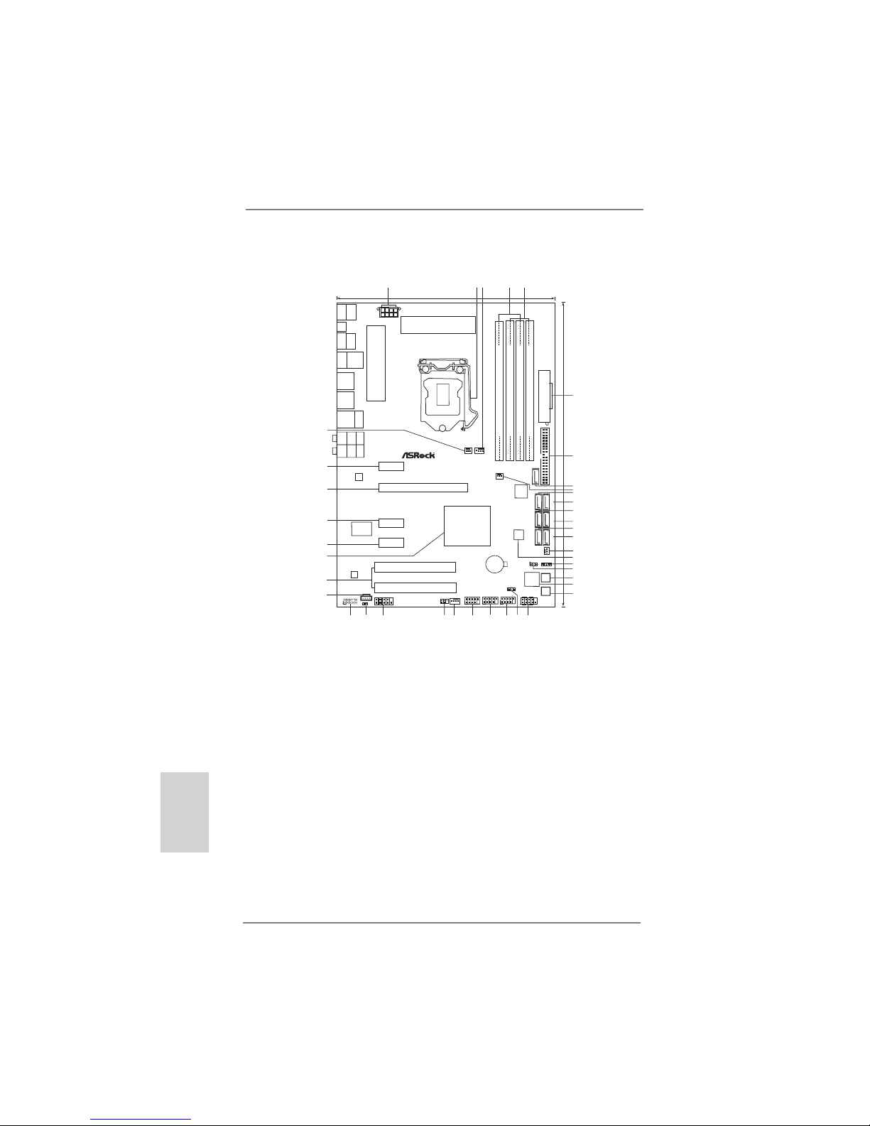
Motherboard Layout
English
1 ATX 12V Power Connector (ATX12V1) 21 Dr. Debug
2 1156-Pin CPU Socket 22 Power Switch (PWRBTN)
3 CPU Fan Connector (CPU_FAN1) 23 System Panel Header (PANEL1, White)
4 2 x 240-pin DDR3 DIMM Slots 24 Power LED Header (PLED1)
(Dual Channel: DDR3_A2, DDR3_B2, Blue) 25 USB 2.0 Header (USB12_13, Blue)
5 2 x 240-pin DDR3 DIMM Slots 26 USB 2.0 Header (USB10_11, Blue)
(Dual Channel: DDR3_A1, DDR3_B1, White) 27 USB 2.0 Header (USB8_9, Blue)
6 ATX Power Connector (ATXPWR1) 28 Chassis Fan Connector (CHA_FAN1)
7 Primary IDE Connector (IDE1, Blue) 29 Infrared Module Header (IR1)
8 SATA2 Connector (SATAII_6, Blue) 30 COM Port Header (COM1)
9 Chassis Fan Connector (CHA_FAN3) 31 HDMI_SPDIF Header
10 SATA3 Connector (SATAIII_1, White) (HDMI_SPDIF1, White)
11 SATA3 Connector (SATAIII_0, White) 32 Front Panel Audio Header
12 SATA2 Connector (SATAII_3, Blue) (HD_AUDIO1, White)
13 SATA2 Connector (SATAII_2, Blue) 33 Internal Audio Connector: CD1 (White)
14 SATA2 Connector (SATAII_5, Blue) 34 PCI Slots (PCI1-2)
15 SATA2 Connector (SATAII_4, Blue) 35 Intel P67 Chipset
16 Chassis Fan Connector (CHA_FAN2) 36 PCI Express 2.0 x1 Slot (PCIE4, White)
17 64Mb SPI Flash 37 PCI Express 2.0 x1 Slot (PCIE3, White)
18 Chassis Speaker Header (SPEAKER 1, White) 38 PCI Express 2.0 x16 Slot (PCIE2, Blue)
19 Clear CMOS Jumper (CLRCMOS1) 39 PCI Express 2.0 x1 Slot (PCIE1, White)
20 Reset Switch (RSTBTN) 40 Power Fan Connector (PWR_FAN1)
Intel
P67
30.5cm (12.0in)
21.8cm (8.6in)
CMOS
Battery
DDR3_A2(64 bit, 240-pinmodule)
DDR3_A1(64 bit, 240-pinmodule)
DDR3_B2(64 bit, 240-pinmodule)
DDR3_B1(64 bit, 240-pinmodule)
ATXPWR1
HDLED RESET
PLEDPWRBTN
PANEL1
1
USB8_9
11
IDE1
SATAII_4_5
SATAII_2_3
SATAIII_0_1
64Mb
BIOS
P67 Transformer
ATX12V1
DDR3 2600+
PS2
Mouse
Coaxial
SPDIF
PS2
Keyboard
Optical
SPDIF
Clr
CMOS
USB2.0
T:USB0
B:USB1
Top:
SIDE SPK
Center:
REAR SPK
Bottom:
CTR BASS
Top:
LINE IN
Center:
FRONT
Bottom:
MIC IN
LAN
PHY
1
HD_AUDIO1
CHA_FAN3
CHA_FAN1
PWRBTN
RSTBTN
Dr.
Debug
AUDIO
CODEC
CD1
Super
I/O
IR1
1
COM1
1
1
HDMI_SPDIF1
USB 3.0
RoHS
1
2
3
4
5
6
7
8
9
10
11
12
13
14
15
16
17
24
25
23
18
19
20
21
22
26
27
28
29
30
31
32
33
34
35
36
37
38
USB10_11
11
USB12_13
1
CHA_FAN2
PWR_FAN1
CPU_FAN1
PCIE1
Dual Channel
PCI Express2.0 SATA3 6Gb/s
USB2.0
T:USB4
B:USB5
Top:
RJ-45
PCIE2
PCIE3
PCI1
PCI2
JMicron
JMB363
ErP/EuP Ready
USB2.0
T:USB6
B:USB7
eSATAII_1
SATAII_6
SPEAKER1
1
PLED1
1
Designed inTaipei
39
40
USB3.0
T:USB2
B:USB3
PCIE4
CLRCMOS1
1
3
ASRock P67 Transformer Motherboard
English
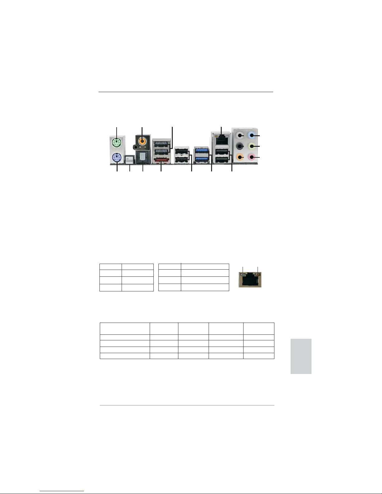
I/O Panel
**
If you use 2-channel speaker, please connect the speaker’s plug into “Front Speaker Jack”.
See the table below for connection details in accordance with the type of speaker you use.
TABLE for Audio Output Connection
Audio Output Channels Front Speaker Rear Speaker Central / Bass Side Speaker
(No. 9) (No. 6) (No. 7) (No. 5)
2 V -- -- -4 V V -- -6 V V V -8 V V V V
* There are two LED next to the LAN port. Please refer to the table below for the LAN port LED
indications.
LAN Port LED Indications
Activity/Link LED SPEED LED
Status Description Status Description
Off No Link Off 10Mbps connection
Blinking Data Activity Orange 100Mbps connection
On Link Green 1Gbps connection
ACT/LINK
LED
SPEED
LED
LAN Port
1 PS/2 Mouse Port (Green) 10 Microphone (Pink)
2 Coaxial SPDIF Out Port 11 USB 2.0 Ports (USB45)
3 USB 2.0 Port (USB67) 12 USB 3.0 Ports (USB23)
* 4 LAN RJ-45 Port 13 USB 2.0 Ports (USB01)
5 Side Speaker (Gray) 14 eSATA2 Connector (eSATAII_1)
6 Rear Speaker (Black) 15 Optical SPDIF Out Port
7 Central / Bass (Orange) 16 Clear CMOS Switch (CLRCBTN)
8 Line In (Light Blue) 17 PS/2 Keyboard Port (Purple)
** 9 Front Speaker (Lime)
1
2
4
3
5
6
7
8
9
10
12
13
11
15
14
17
16

4
ASRock P67 Transformer Motherboard
To enable Multi-Streaming function, you need to connect a front panel audio cable to the front
panel audio header. After restarting your computer, you will fi nd “Mixer” tool on your system.
Please select “Mixer ToolBox” , click “Enable playback multi-streaming”, and click
“ok”. Choose “2CH”, “4CH”, “6CH”, or “8CH” and then you are allowed to select “Realtek HDA
Primary output” to use Rear Speaker, Central/Bass, and Front Speaker, or select “Realtek
HDA Audio 2nd output” to use front panel audio.
English

5
ASRock P67 Transformer Motherboard
1. Introduction
Thank you for purchasing ASRock P67 Transformer motherboard, a reliable motherboard produced under ASRock’s consistently stringent quality control. It delivers
excellent performance with robust design conforming to ASRock’s commitment to
quality and endurance.
This Quick Installation Guide contains introduction of the motherboard and step-bystep installation guide. More detailed information of the motherboard can be found
in the user manual presented in the Support CD.
Because the motherboard specifi cations and the BIOS software might be
updated, the content of this manual will be subject to change without notice. In case any modifi cations of this manual occur, the updated version
will be available on ASRock website without further notice. You may fi nd
the latest VGA cards and CPU support lists on ASRock website as well.
ASRock website http://www.asrock.com
If you require technical support related to this motherboard, please visit
our website for specifi c information about the model you are using.
www.asrock.com/support/index.asp
1.1 Package Contents
ASRock P67 Transformer Motherboard
(ATX Form Factor: 12.0-in x 8.6-in, 30.5 cm x 21.8 cm)
ASRock P67 Transformer Quick Installation Guide
ASRock P67 Transformer Support CD
2 x Serial ATA (SATA) Data Cables (Optional)
1 x I/O Panel Shield
English
ASRock Reminds You...
To get better performance in Windows® 7 / 7 64-bit / Vista
TM
/ VistaTM 64bit, it is recommended to set the BIOS option in Storage Confi guration to
AHCI mode. For the BIOS setup, please refer to the “User Manual” in our
support CD for details.
6
ASRock P67 Transformer Motherboard
English
1.2 Specifications
Platform - ATX Form Factor: 12.0-in x 8.6-in, 30.5 cm x 21.8 cm
- All Solid Capacitor design (100% Japan-made high-quality
Conductive Polymer Capacitors)
CPU - Supports Intel
®
Lynnfi eld CoreTM i7 / i5 Processors in
LGA1156 Package
- Advanced V8 + 2 Power Phase Design
- Supports Intel® Turbo Boost Technology
- Supports Hyper-Threading Technology (see CAUTION 1)
- Supports Untied Overclocking Technology (see CAUTION 2)
Chipset - Intel
®
P67
Memory - Dual Channel DDR3 Memory Technology (see CAUTION 3)
- 4 x DDR3 DIMM slots
- Supports DDR3 2600+(OC)/2133(OC)/1866(OC)/1600/
1333/1066 non-ECC, un-buffered memory
- Max. capacity of system memory: 16GB (see CAUTION 4)
- Supports Intel
®
Extreme Memory Profi le (XMP)
Expansion Slot - 1 x PCI Express 2.0 x16 slot (blue @ x16 mode)
- 3 x PCI Express 2.0 x1 slots
- 2 x PCI slots
Audio - 7.1 CH HD Audio with Content Protection
(Realtek ALC892 Audio Codec)
- Premium Blu-ray audio support
LAN - PCIE x1 Gigabit LAN 10/100/1000 Mb/s
- Realtek RTL8111E
- Supports Wake-On-LAN
- Supports LAN Cable Detection
- Supports Energy Effi cient Ethernet 802.3az
Rear Panel I/O I/O Panel
- 1 x PS/2 Mouse Port
- 1 x PS/2 Keyboard Port
- 1 x Coaxial SPDIF Out Port
- 1 x Optical SPDIF Out Port
- 6 x Ready-to-Use USB 2.0 Ports
- 1 x eSATA2 Connector
- 2 x Ready-to-Use USB 3.0 Ports
- 1 x RJ-45 LAN Port with LED (ACT/LINK LED and SPEED
LED)
- 1 x Clear CMOS Switch with LED

7
ASRock P67 Transformer Motherboard
English
- HD Audio Jack: Side Speaker/Rear Speaker/Central/Bass/
Line in/Front Speaker/Microphone (see CAUTION 5)
SATA 3 - 2 x SATA3 6.0 Gb/s connectors, support RAID (RAID 0,
RAID 1, RAID 10, RAID 5 and Intel Rapid Storage), NCQ,
AHCI and "Hot Plug" functions
USB3.0 - 2 x USB 3.0 ports by Etron EJ168A, support
USB 1.0/2.0/3.0 up to 5Gb/s
Connector - 5 x SATA2 3.0 Gb/s connectors, support RAID (RAID 0,
RAID 1, RAID 10, RAID 5 and Intel Rapid Storage), NCQ,
AHCI and Hot Plug functions
* JMicron SATAII_6 does not support RAID function.
- 2 x SATA3 6.0Gb/s connectors
- 1 x ATA133 IDE connector (supports 2 x IDE devices)
- 1 x IR header
- 1 x COM port header
- 1 x HDMI_SPDIF header
- 1 x Power LED header
- CPU/Chassis/Power FAN connector
- 24 pin ATX power connector
- 8 pin 12V power connector
- CD in header
- Front panel audio connector
- 3 x USB 2.0 headers (support 6 USB 2.0 ports)
- 1 x Dr. Debug (7-Segment Debug LED)
Smart Switch - 1 x Clear CMOS Switch with LED
- 1 x Power Switch with LED
- 1 x Reset Switch with LED
BIOS Feature - 64Mb AMI BIOS
- AMI UEFI Legal BIOS with GUI support
- Supports “Plug and Play”
- ACPI 1.1 Compliance Wake Up Events
- Supports jumperfree
- SMBIOS 2.3.1 Support
- DRAM, PCH, CPU PLL, VTT Voltage Multi-adjustment
- Supports I. O. T. (Intelligent Overclocking Technology)
Support CD - Drivers, Utilities, AntiVirus Software (Trial Version), ASRock
Software Suite (CyberLink DVD Suite - OEM and Trial;
Creative Sound Blaster X-Fi MB - Trial)
Unique Feature - ASRock Extreme Tuning Utility (AXTU) (see CAUTION 6)
- Instant Boot
- ASRock Instant Flash (see CAUTION 7)
- ASRock AIWI (see CAUTION 8)

8
ASRock P67 Transformer Motherboard
English
- ASRock APP Charger (see CAUTION 9)
- SmartView (see CAUTION 10)
- Hybrid Booster:
- CPU Frequency Stepless Control (see CAUTION 11)
- ASRock U-COP (see CAUTION 12)
- Boot Failure Guard (B.F.G.)
- Combo Cooler Option (C.C.O.) (see CAUTION 13)
- Good Night LED
- Turbo 40 / Turbo 50 Technology
Hardware - CPU Temperature Sensing
Monitor - Chassis Temperature Sensing
- CPU/Chassis/Power Fan Tachometer
- CPU/Chassis Quiet Fan (Allow Chassis Fan Speed
Auto-Adjust by CPU or MB Temperature)
- CPU/Chassis Fan Multi-Speed Control
- Voltage Monitoring: +12V, +5V, +3.3V, CPU Vcore
OS - Microsoft
®
Windows® 7 / 7 64-bit / Vista
TM
/ VistaTM 64-bit
/ XP / XP 64-bit compliant
Certifi cations - FCC, CE, WHQL
- ErP/EuP Ready (ErP/EuP ready power supply is required)
(see CAUTION 14)
* For detailed product information, please visit our website: http://www.asrock.com
WARNING
Please realize that there is a certain risk involved with overclocking, including
adjusting the setting in the BIOS, applying Untied Overclocking Technology, or
using the third-party overclocking tools. Overclocking may affect your system
stability, or even cause damage to the components and devices of your system.
It should be done at your own risk and expense. We are not responsible for possible
damage caused by overclocking.

9
ASRock P67 Transformer Motherboard
English
CAUTION!
1. About the setting of “Hyper Threading Technology”, please check page
43 of “User Manual” in the support CD.
2. This motherboard supports Untied Overclocking Technology. Please read
“Untied Overclocking Technology” on page 31 for details.
3. This motherboard supports Dual Channel Memory Technology. Before
you implement Dual Channel Memory Technology, make sure to read the
installation guide of memory modules on page 15 for proper installation.
4. Due to the operating system limitation, the actual memory size may be
less than 4GB for the reservation for system usage under Windows
®
7 /
Vista
TM
/ XP. For Windows® OS with 64-bit CPU, there is no such limita-
tion.
5. For microphone input, this motherboard supports both stereo and mono
modes. For audio output, this motherboard supports 2-channel, 4-channel, 6-channel, and 8-channel modes. Please check the table on page 3
for proper connection.
6. ASRock Extreme Tuning Utility (AXTU) is an all-in-one tool to fi ne-tune
different system functions in a user-friendly interface, which is including
Hardware Monitor, Fan Control, Overclocking, OC DNA and IES. In
Hardware Monitor, it shows the major readings of your system. In Fan
Control, it shows the fan speed and temperature for you to adjust. In
Overclocking, you are allowed to overclock CPU frequency for optimal
system performance. In OC DNA, you can save your OC settings as a
profi le and share with your friends. Your friends then can load the OC
profi le to their own system to get the same OC settings. In IES (Intelligent
Energy Saver), the voltage regulator can reduce the number of output
phases to improve efficiency when the CPU cores are idle without
sacrificing computing performance. Please visit our website for the
operation procedures of ASRock Extreme Tuning Utility (AXTU).
ASRock website: http://www.asrock.com
7. ASRock Instant Flash is a BIOS fl ash utility embedded in Flash ROM.
This convenient BIOS update tool allows you to update system BIOS
without entering operating systems fi rst like MS-DOS or Windows®. With
this utility, you can press <F6> key during the POST or press <F2> key to
BIOS setup menu to access ASRock Instant Flash. Just launch this tool
and save the new BIOS fi le to your USB fl ash drive, fl oppy disk or hard
drive, then you can update your BIOS only in a few clicks without preparing an additional fl oppy diskette or other complicated fl ash utility. Please
be noted that the USB fl ash drive or hard drive must use FAT32/16/12 fi le
system.

10
ASRock P67 Transformer Motherboard
English
8. To experience intuitive motion controlled games is no longer only avail-
able at Wii. ASRock AIWI utility introduces a new way of PC gaming
operation. ASRock AIWI is the world's fi rst utility to turn your iPhone/iPod
touch as a game joystick to control your PC games. All you have to do is
just to install the ASRock AIWI utility either from ASRock offi cial website
or ASRock software support CD to your motherboard, and also download
the free AIWI Lite from App store to your iPhone/iPod touch. Connecting
your PC and apple devices via Bluetooth or WiFi networks, then you can
start experiencing the exciting motion controlled games. Also, please do
not forget to pay attention to ASRock offi cial website regularly, we will
continuously provide you the most up-do-date supported games!
ASRock website: http://www.asrock.com/Feature/Aiwi/index.asp
9. If you desire a faster, less restricted way of charging your Apple devices,
such as iPhone/iPod/iPad Touch, ASRock has prepared a wonderful
solution for you - ASRock APP Charger. Simply installing the APP Char-
ger driver, it makes your iPhone charged much quickly from your com-
puter and up to 40% faster than before. ASRock APP Charger allows you
to quickly charge many Apple devices simultaneously and even supports
continuous charging when your PC enters into Standby mode (S1), Sus-
pend to RAM (S3), hibernation mode (S4) or power off (S5). With APP
Charger driver installed, you can easily enjoy the marvelous charging
experience than ever.
ASRock website: http://www.asrock.com/Feature/AppCharger/index.asp
10.
SmartView, a new function of internet browser, is the smart start page for
IE that combines your most visited web sites, your history, your Facebook
friends and your real-time newsfeed into an enhanced view for a more
personal Internet experience. ASRock motherboards are exclusively
equipped with the SmartView utility that helps you keep in touch with
friends on-the-go. To use SmartView feature, please make sure your
OS version is Windows
®
7 / 7 64 bit / VistaTM / VistaTM 64 bit, and your
browser version is IE8.
ASRock website: http://www.asrock.com/Feature/
SmartView/index.asp
11. Although this motherboard offers stepless control, it is not recommended
to perform over-clocking. Frequencies other than the recommended CPU
bus frequencies may cause the instability of the system or damage the
CPU.
12. While CPU overheat is detected, the system will automatically shutdown.
Before you resume the system, please check if the CPU fan on the
motherboard functions properly and unplug the power cord, then plug it
back again. To improve heat dissipation, remember to spray thermal
grease between the CPU and the heatsink when you install the PC sys-
tem.
13. Combo Cooler Option (C.C.O.) provides the fl exible option to adopt two
different CPU cooler types, Socket LGA 775 and LGA 1156. Please
benoticed that not all the 775 CPU Fan can be used.

11
ASRock P67 Transformer Motherboard
English
14. EuP, stands for Energy Using Product, was a provision regulated by European Union to defi ne the power consumption for the completed system.
According to EuP, the total AC power of the completed system shall be
under 1.00W in off mode condition. To meet EuP standard, an EuP ready
motherboard and an EuP ready power supply are required. According to
Intel’s suggestion, the EuP ready power supply must meet the standard
of 5v standby power effi ciency is higher than 50% under 100 mA current
consumption. For EuP ready power supply selection, we recommend you
checking with the power supply manufacturer for more details.
12
ASRock P67 Transformer Motherboard
2. Installation
Pre-installation Precautions
Take note of the following precautions before you install motherboard components or change any motherboard settings.
1. Unplug the power cord from the wall socket before touching any
component. Failure to do so may cause severe damage to the
motherboard, peripherals, and/or components.
2. To avoid damaging the motherboard components due to static
electricity, NEVER place your motherboard directly on the carpet or the like. Also remember to use a grounded wrist strap or
touch a safety grounded object before you handle components.
3. Hold components by the edges and do not touch the ICs.
4. Whenever you uninstall any component, place it on a grounded
antstatic pad or in the bag that comes with the component.
5. When placing screws into the screw holes to secure the moth-
erboard to the chassis, please do not over-tighten the screws!
Doing so may damage the motherboard.
2.1 CPU Installation
For the installation of Intel 1156-Pin CPU,
please follow the steps below.
Before you insert the 1156-Pin CPU into the socket, please check if the
CPU surface is unclean or if there is any bent pin on the socket. Do not
force to insert the CPU into the socket if above situation is found. Otherwise, the CPU will be seriously damaged.
1156-Pin Socket Overview
English
ContactArray
SocketBody
LoadLever
LoadPlate
13
ASRock P67 Transformer Motherboard
English
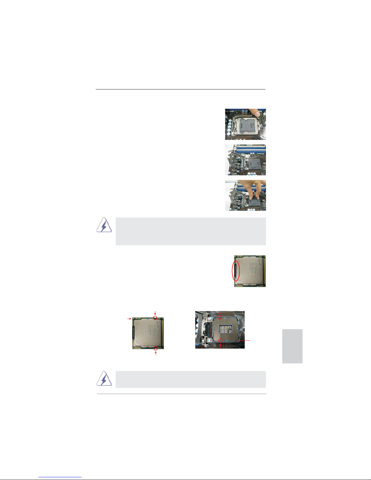
Step 1. Open the socket:
Step 1-1. Disengaging the lever by depressing
down and out on the hook to clear
retention tab.
Step 1-2. Rotate the load lever to fully open po-
sition at approximately 135 degrees.
Step 1-3. Rotate the load plate to fully open po-
sition at approximately 100 degrees.
Step 2. Remove PnP Cap (Pick and Place Cap).
1. It is recommended to use the cap tab to handle and avoid kicking
off the PnP cap.
2. This cap must be placed if returning the motherboard for after
service.
Step 3. Insert the 1156-Pin CPU:
Step 3-1. Hold the CPU by the edges where
are marked with black lines.
Step 3-2. Orient the CPU with IHS (Integrated
Heat Sink) up. Locate Pin1 and the
two orientation key notches.
For proper inserting, please ensure to match the two orientation key
notches of the CPU with the two alignment keys of the socket.
black line
Pin1
alignment key
alignment key
Pin1
1156-Pin CPU
1156-Pin Socket
orientation key notch
orientation key notch

14
ASRock P67 Transformer Motherboard
Step 3-3. Carefully place the CPU into the
socket by using a purely vertical motion.
Step 3-4. Verify that the CPU is within the sock-
et and properly mated to the orient
keys.
Step 4. Close the socket:
Step 4-1. Rotate the load plate onto the IHS.
Step 4-2. While pressing down lightly on load
plate, engage the load lever.
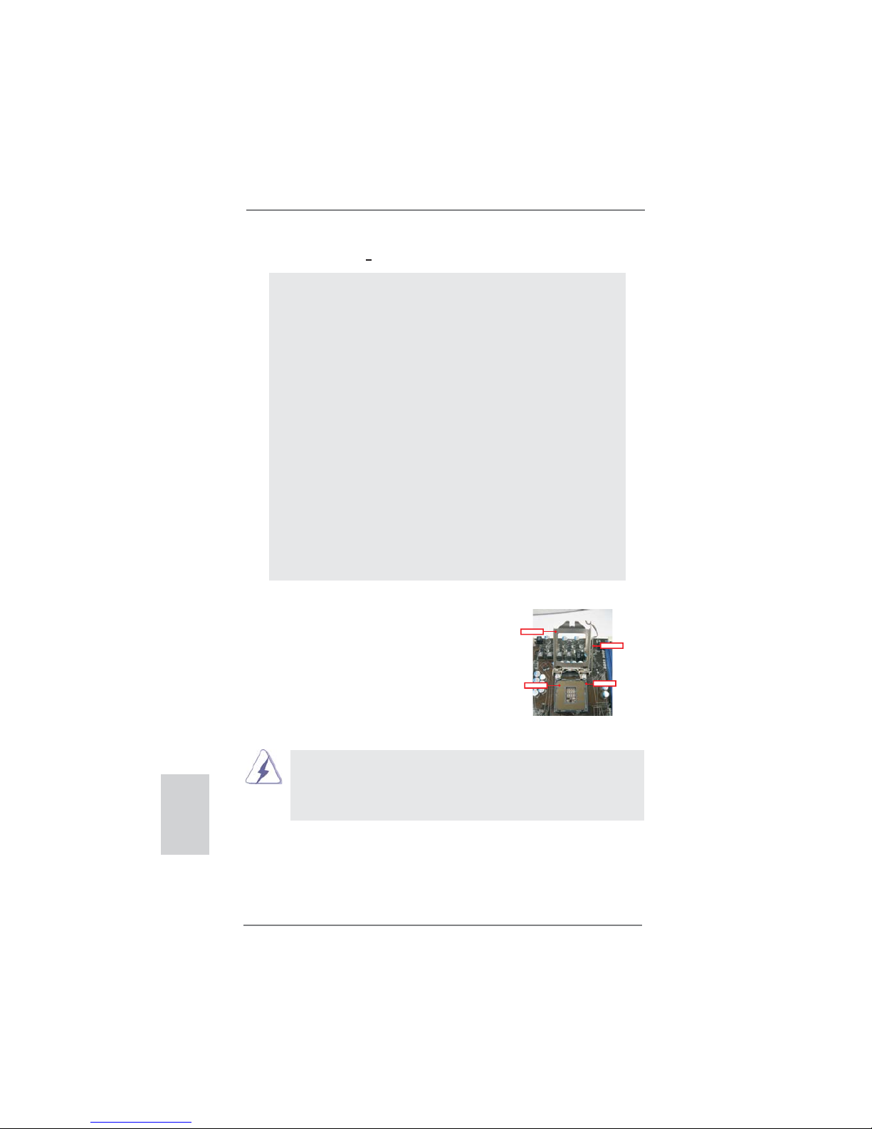
2.2 Installation of CPU Fan and Heatsink
For proper installation, please kindly refer to the instruction manuals of your CPU
fan and heatsink.
Below is an example to illustrate the installation of the heatsink for 1156-Pin CPU.
Step 1. Apply thermal interface material onto center of
IHS on the socket surface.
Step 2. Place the heatsink onto the socket. Ensure
fan cables are oriented on side closest to the
CPU fan connector on the motherboard (CPU_
FAN1, see page 2, No. 3).
Step 3. Align fasteners with the motherboard through-
holes.
Step 4. Rotate the fastener clockwise, then press
down on fastener caps with thumb to install
and lock. Repeat with remaining fasteners.
If you press down the fasteners without rotating them clockwise, the
heatsink cannot be secured on the motherboard.
Step 5. Connect fan header with the CPU fan connector on the motherboard.
Step 6. Secure excess cable with tie-wrap to ensure cable does not interfere with
fan operation or contact other components.
English
ApplyThermal
InterfaceMaterial
Fancables on side
closestto MB header
Fastenerslots
pointingstraight out
PressDown
(4Places)
Please be noticed that this motherboard supports Combo Cooler
Option (C.C.O.), which provides the fl exible option to adopt two
different CPU cooler types, Socket LGA 775 and LGA 1156. The
white throughholes are for Socket LGA
1156 CPU fan.

15
ASRock P67 Transformer Motherboard
English
2.3 Installation of Memory Modules (DIMM)
This motherboard provides four 240-pin DDR3 (Double Data Rate 3) DIMM
slots, and supports Dual Channel Memory Technology. For dual channel confi guration, you always need to install identical (the same brand, speed, size
and chiptype) DDR3 DIMM pair in the slots of the same color. In other words,
you have to install identical DDR3 DIMM pair in Dual Channel (DDR3_A1 and
DDR3_B1; white slots; see p.2 No.5), so that Dual Channel Memory Technology can be activated. This motherboard also allows you to install four DDR3
DIMMs for dual channel configuration, and please install identical DDR3
DIMMs in all four slots. You may refer to the Dual Channel Memory Confi gura-
tion Table below.
Dual Channel Memory Confi gurations
DDR3_A2 DDR3_A1 DDR3_B2 DDR3_B1
(Blue Slot) (White Slot) (Blue Slot) (White Slot)
(1) - Populated - Populated
(2)* Populated Populated Populated Populated
*
For the confi guration (2), please install identical DDR3 DIMMs in all four
slots.
1. If you want to install two memory modules, for optimal compatibility
and reliability, it is recommended to install them in the slots of the
same color. In other words, install them either in the set of white
slots (DDR3_A1 and DDR3_B1).
2. If only one memory module or three memory modules are installed
in the DDR3 DIMM slots on this motherboard, it is unable to
activate the Dual Channel Memory Technology.
3. It is not allowed to install a DDR or DDR2 memory module
into DDR3 slot;otherwise, this motherboard and DIMM may be
damaged.
4. Please install the memory module into the white slot (DDR3_B1) for
the fi rst priority.
16
ASRock P67 Transformer Motherboard
notch
break
notch
break
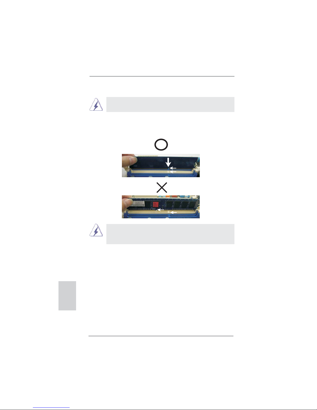
Installing a DIMM
Please make sure to disconnect power supply before adding or
removing DIMMs or the system components.
Step 1. Unlock a DIMM slot by pressing the retaining clips outward.
Step 2. Align a DIMM on the slot such that the notch on the DIMM matches the
break on the slot.
The DIMM only fi ts in one correct orientation. It will cause permanent
damage to the motherboard and the DIMM if you force the DIMM into the slot
at incorrect orientation.
Step 3. Firmly insert the DIMM into the slot until the retaining clips at both ends
fully snap back in place and the DIMM is properly seated.
English

17
ASRock P67 Transformer Motherboard
English
2.4 Expansion Slots (PCI and PCI Express Slots)
There are 2 PCI slots and 4 PCI Express slots on this motherboard.
PCI slots: PCI slots are used to install expansion cards that have the 32-bit PCI
interface.
PCIE slots:
PCIE1 / PCIE3 / PCIE4 (PCIE x1 slot; White) is used for PCI Express
cards with x1 lane width cards, such as Gigabit LAN card, SATA2 card,
etc.
PCIE2 (PCIE x16 slot; Blue) is used for PCI Express x16 lane width
graphics cards.
Installing an expansion card
Step 1. Before installing the expansion card, please make sure that the power
supply is switched off or the power cord is unplugged. Please read the
documentation of the expansion card and make necessary hardware
settings for the card before you start the installation.
Step 2. Remove the system unit cover (if your motherboard is already installed
in a chassis).
Step 3. Remove the bracket facing the slot that you intend to use. Keep the
screws for later use.
Step 4. Align the card connector with the slot and press fi rmly until the card is
completely seated on the slot.
Step 5. Fasten the card to the chassis with screws.
Step 6. Replace the system cover.

18
ASRock P67 Transformer Motherboard
2.5 Jumpers Setup
The illustration shows how jumpers are
setup. When the jumper cap is placed on
pins, the jumper is “Short”. If no jumper cap
is placed on pins, the jumper is “Open”. The
illustration shows a 3-pin jumper whose
pin1 and pin2 are “Short” when jumper cap
is placed on these 2 pins.
Jumper Setting Description
Clear CMOS Jumper
(CLRCMOS1)
(see p.2, No. 19)
Note: CLRCMOS1 allows you to clear the data in CMOS. To clear and reset the
system parameters to default setup, please turn off the computer and unplug
the power cord from the power supply. After waiting for 15 seconds, use a
jumper cap to short pin2 and pin3 on CLRCMOS1 for 5 seconds. However,
please do not clear the CMOS right after you update the BIOS. If you need
to clear the CMOS when you just fi nish updating the BIOS, you must boot
up the system fi rst, and then shut it down before you do the clear-CMOS ac-
tion. Please be noted that the password, date, time, user default profi le, 1394
GUID and MAC address will be cleared only if the CMOS battery is removed.
Clear CMOSDefault
English
The Clear CMOS Switch has the same function as the Clear CMOS
jumper.

19
ASRock P67 Transformer Motherboard
English
Serial ATA (SATA) Either end of the SATA data
Data Cable cable can be connected to the
(Optional)
SATA / SATAII / SATA3 hard
disk or the SATAII / SATA3
connector on this motherboard.
Primary IDE connector (Blue)
(39-pin IDE1, see p.2 No. 7)
Note: Please refer to the instruction of your IDE device vendor for the details.
connect the black end
to the IDE devices
connect the blue end
to the motherboard
80-conductor ATA 66/100/133 cable
Serial ATAII Connectors These fi ve Serial ATAII (SATAII)
(SATAII_2: see p.2, No. 13)
connectors support SATA data
(SATAII_3: see p.2, No. 12)
cables for internal storage
(SATAII_4: see p.2, No. 15)
devices. The current SATAII
(SATAII_5: see p.2, No. 14)
interface allows up to 3.0 Gb/s
(SATAII_6: see p.2, No. 8)
data transfer rate.
Serial ATA3 Connectors These two Serial ATA3 (SATA3)
(SATAIII_0: see p.2, No. 11)
connectors support SATA data
(SATAIII_1: see p.2, No. 10)
cables for internal storage
devices. The current SATA3
interface allows up to 6.0 Gb/s
data transfer rate.
2.6 Onboard Headers and Connectors
Onboard headers and connectors are NOT jumpers. Do NOT place
jumper caps over these headers and connectors. Placing jumper caps
over the headers and connectors will cause permanent damage of the
motherboard!
SATAII_5 SATAII_3
SATAII_4 SATAII_2
SATAII_6
SATAIII_1
SATAIII_0

20
ASRock P67 Transformer Motherboard
English
Infrared Module Header This header supports an
(5-pin IR1)
optional wireless transmitting
(see p.2 No. 29)
and receiving infrared module.
USB 2.0 Headers Besides six default USB 2.0
(9-pin USB8_9)
ports on the I/O panel, there
(see p.2 No. 27)
are three USB 2.0 headers on
this motherboard. Each
USB 2.0 header can support
two USB 2.0 ports.
(9-pin USB10_11)
(see p.2 No. 26)
(9-pin USB12_13)
(see p.2 No. 25)
1
IRTX
+5VSB
DUMMY
IRRX
GND
1
DUMMY
GND
P+13
P-13
USB_PWR
USB_PWR
GND
P+12
P-12
1
USB_PWR
P-8
GND
DUMMY
USB_PWR
P+8
GND
P-9
P+9
1
USB_PW R
P-10
GND
DUMMY
USB_PW R
P+10
GND
P-11
P+11
J_SENSE
OUT2_L
1
MIC_RET
PRESENCE#
GND
OUT2_R
MIC2_R
MIC2_L
OUT_RET
Front Panel Audio Header This is an interface for front
(9-pin HD_AUDIO1)
panel audio cable that allows
(see p.2 No. 32)
convenient connection and
control of audio devices.
Internal Audio Connectors This connector allows you
(4-pin CD1)
to receive stereo audio input
(CD1: see p.2 No. 33)
from sound sources such as
a CD-ROM, DVD-ROM, TV
tuner card, or MPEG card.
CD1
CD-L
GND
GND
CD-R

21
ASRock P67 Transformer Motherboard
English
1. High Defi nition Audio supports Jack Sensing, but the panel wire on
the chassis must support HDA to function correctly. Please follow the
instruction in our manual and chassis manual to install your system.
2. If you use AC’97 audio panel, please install it to the front panel audio
header as below:
A. Connect Mic_IN (MIC) to MIC2_L.
B. Connect Audio_R (RIN) to OUT2_R and Audio_L (LIN) to OUT2_L.
C. Connect Ground (GND) to Ground (GND).
D. MIC_RET and OUT_RET are for HD audio panel only. You don’t
need to connect them for AC’97 audio panel.
E. To activate the front mic.
For Windows
®
XP / XP 64-bit OS:
Select “Mixer”. Select “Recorder”. Then click “FrontMic”.
For Windows® 7 / 7 64-bit / VistaTM / VistaTM 64-bit OS:
Go to the "FrontMic" Tab in the Realtek Control panel. Adjust
“Recording Volume”.
System Panel Header This header accommodates
(9-pin PANEL1)
several system front panel
(see p.2 No. 23)
functions.
Connect the power switch, reset switch and system status indicator on the
chassis to this header according to the pin assignments below. Note the
positive and negative pins before connecting the cables.
PWRBTN (Power Switch):
Connect to the power switch on the chassis front panel. You may confi gure
the way to turn off your system using the power switch.
RESET (Reset Switch):
Connect to the reset switch on the chassis front panel. Press the reset
switch to restart the computer if the computer freezes and fails to perform a
normal restart.
PLED (System Power LED):
Connect to the power status indicator on the chassis front panel. The LED
is on when the system is operating. The LED keeps blinking when the system is in S1 sleep state. The LED is off when the system is in S3/S4 sleep
state or powered off (S5).
HDLED (Hard Drive Activity LED):
Connect to the hard drive activity LED on the chassis front panel. The LED
is on when the hard drive is reading or writing data.

22
ASRock P67 Transformer Motherboard
English
Chassis and Power Fan Connectors Please connect the fan cables
(4-pin CHA_FAN1)
to the fan connectors and
(see p.2 No. 28)
match the black wire to the
ground pin.
(3-pin CHA_FAN2)
(see p.2 No. 16)
(3-pin CHA_FAN3)
(see p.2 No. 9)
(3-pin PWR_FAN1)
(see p.2 No. 40)
CPU Fan Connectors Please connect the CPU fan
(4-pin CPU_FAN1)
cable to the connector and
(see p.2 No. 3)
match the black wire to the
ground pin.
Chassis Speaker Header Please connect the chassis
(4-pin SPEAKER 1)
speaker to this header.
(see p.2 No. 18)
Power LED Header Please connect the chassis
(3-pin PLED1)
power LED to this header to
(see p.2 No. 24)
indicate system power status.
The LED is on when the system
is operating. The LED keeps
blinking in S1 state. The LED is
off in S3/S4 state or S5 state
(power off).
1
PLED+
PLED+
PLED-
The front panel design may differ by chassis. A front panel module mainly
consists of power switch, reset switch, power LED, hard drive activity LED,
speaker and etc. When connecting your chassis front panel module to this
header, make sure the wire assignments and the pin assign-ments are
matched correctly.
Though this motherboard provides 4-Pin CPU fan (Quiet Fan) support, the 3-Pin
CPU fan still can work successfully even without the fan speed control function.
If you plan to connect the 3-Pin CPU fan to the CPU fan connector on this
motherboard, please connect it to Pin 1-3.
3-Pin Fan Installation
Pin 1-3 Connected
GND
+12V
CHA_FAN_SPEED
FAN_SPEED_CONTROL
GND
CHA_FAN2_PWR
CHA_FAN_SPEED
4 3 2 1
GND
+12V
CPU_FAN_SPEED
FAN_SPEED_CONTROL

23
ASRock P67 Transformer Motherboard
English
ATX Power Connector Please connect an ATX power
(24-pin ATXPWR1)
supply to this connector.
(see p.2 No. 6)
12 124
13
20-Pin ATX Power Supply Installation
Though this motherboard provides 24-pin ATX power connector,
it can still work if you adopt a traditional 20-pin ATX power supply.
To use the 20-pin ATX power supply, please plug your
power supply along with Pin 1 and Pin 13.
12
1
24
13
ATX 12V Power Connector Please connect an ATX 12V
(8-pin ATX12V1)
power supply to this connector.
(see p.2 No. 1)
4-Pin ATX 12V Power Supply Installation
Though this motherboard provides 8-pin ATX 12V power connector, it can still work
if you adopt a traditional 4-pin ATX 12V power supply. To use the 4-pin ATX power
supply, please plug your power supply along with Pin 1 and Pin 5.
8 5
4 1
8 5
4 1
HDMI_SPDIF Header HDMI_SPDIF header, providing
(2-pin HDMI_SPDIF1)
SPDIF audio output to HDMI
(see p.2 No. 31)
VGA card, allows the system to
connect HDMI Digital TV/
projector/LCD devices. Please
connect the HDMI_SPDIF
connector of HDMI VGA card to
this header.
SPDIFOUT
GND
1
Serial port Header This COM1 header supports a
(9-pin COM1)
serial port module.
(see p.2 No. 30)

24
ASRock P67 Transformer Motherboard
English
Reset Switch Reset Switch is a smart switch,
(RSTBTN)
allowing users to quickly reset
(see p.2 No. 20)
the system.
RESET
Clear CMOS Switch Clear CMOS Switch is a smart
(CLRCBTN)
switch, allowing users to quickly
(see p.3 No. 16)
clear the CMOS values.
clr
CMOS
2.7 Smart Switches
The motherboard has three smart switches: power switch, reset switch and clear
CMOS switch, allowing users to quickly turn on/off or reset the sytem clear the
CMOS values.
Power Switch Power Switch is a smart switch,
(PWRBTN)
allowing users to quickly turn
(see p.2 No. 22)
on/off the system.

25
ASRock P67 Transformer Motherboard
English
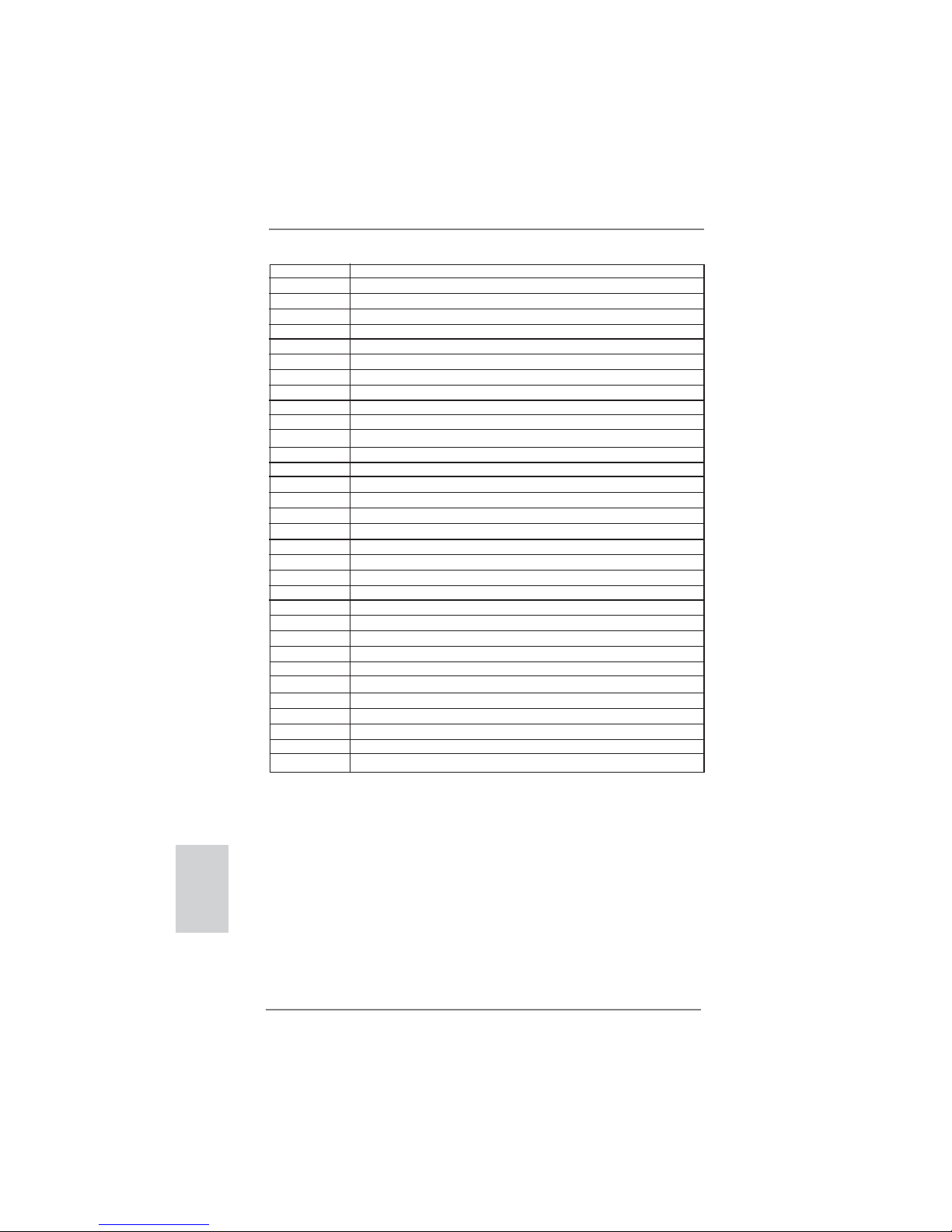
2.8 Dr. Debug
Dr. Debug is used to provide code information, which makes troubleshooting even
easier. Please see the diagrams below for reading the Dr. Debug codes.
Status Code Description
0x00 Not used
0x01 Power on. Reset type detection (soft/hard)
0x02 AP initialization before microcode loading
0x03 North Bridge initialization before microcode loading
0x04 South Bridge initialization before microcode loading
0x05 OEM initialization before microcode loading
0x06 Microcode loading
0x07 AP initialization after microcode loading
0x08 North Bridge initialization after microcode loading
0x09 South Bridge initialization after microcode loading
0x0A OEM initialization after microcode loading
0x0B Cache initialization
0x0C – 0x0D Reserved for future AMI SEC error codes
0x0E Microcode not found
0x0F Microcode not loaded
0x10 PEI Core is started
0x11 Pre-memory CPU initialization is started
0x12 Pre-memory CPU initialization (CPU module specifi c)
0x13 Pre-memory CPU initialization (CPU module specifi c)
0x14 Pre-memory CPU initialization (CPU module specifi c)
0x15 Pre-memory North Bridge initialization is started
0x16 Pre-Memory North Bridge initialization (North Bridge module specifi c)
0x17 Pre-Memory North Bridge initialization (North Bridge module specifi c)
0x18 Pre-Memory North Bridge initialization (North Bridge module specifi c)
0x19 Pre-memory South Bridge initialization is started
0x1A Pre-memory South Bridge initialization (South Bridge module specifi c)
0x1B Pre-memory South Bridge initialization (South Bridge module specifi c)
0x1C Pre-memory South Bridge initialization (South Bridge module specifi c)
0x1D – 0x2A OEM pre-memory initialization codes
0x2B Memory initialization. Serial Presence Detect (SPD) data reading
0x2C Memory initialization. Memory presence detection
0x2D Memory initialization. Programming memory timing information
0x2E Memory initialization. Confi guring memory
0x2F Memory initialization (other)
0x30 Reserved for ASL (see ASL Status Codes section below)
0x31 Memory Installed
0x32 CPU post-memory initialization is started
0x33 CPU post-memory initialization. Cache initialization
0x34 CPU post-memory initialization. Application Processor(s) (AP) initialization
0x35 CPU post-memory initialization. Boot Strap Processor (BSP) selection
0x36 CPU post-memory initialization. System Management Mode (SMM)
initialization

26
ASRock P67 Transformer Motherboard
English
0x37 Post-Memory North Bridge initialization is started
0x38 Post-Memory North Bridge initialization (North Bridge module specifi c)
0x39 Post-Memory North Bridge initialization (North Bridge module specifi c)
0x3A Post-Memory North Bridge initialization (North Bridge module specifi c)
0x3B Post-Memory South Bridge initialization is started
0x3C Post-Memory South Bridge initialization (South Bridge module specifi c)
0x3D Post-Memory South Bridge initialization (South Bridge module specifi c)
0x3E Post-Memory South Bridge initialization (South Bridge module specifi c)
0x3F-0x4E OEM post memory initialization codes
0x4F DXE IPL is started
0x50 Memory initialization error. Invalid memory type or incompatible memory
speed
0x51 Memory initialization error. SPD reading has failed
0x52 Memory initialization error. Invalid memory size or memory modules do not
match
0x53 Memory initialization error. No usable memory detected
0x54 Unspecifi ed memory initialization error
0x55 Memory not installed
0x56 Invalid CPU type or Speed
0x57 CPU mismatch
0x58 CPU self test failed or possible CPU cache error
0x59 CPU micro-code is not found or micro-code update is failed
0x5A Internal CPU error
0x5B reset PPI is not available
0x5C-0x5F Reserved for future AMI error codes
0xE0 S3 Resume is stared (S3 Resume PPI is called by the DXE IPL)
0xE1 S3 Boot Script execution
0xE2 Video repost
0xE3 OS S3 wake vector call
0xE4-0xE7 Reserved for future AMI progress codes
0xE8 S3 Resume Failed
0xE9 S3 Resume PPI not Found
0xEA S3 Resume Boot Script Error
0xEB S3 OS Wake Error
0xEC-0xEF Reserved for future AMI error codes
0xF0 Recovery condition triggered by fi rmware (Auto recovery)
0xF1 Recovery condition triggered by user (Forced recovery)
0xF2 Recovery process started
0xF3 Recovery fi rmware image is found
0xF4 Recovery fi rmware image is loaded
0xF5-0xF7 Reserved for future AMI progress codes
0xF8 Recovery PPI is not available
0xF9 Recovery capsule is not found
0xFA Invalid recovery capsule
0xFB – 0xFF Reserved for future AMI error codes
0x60 DXE Core is started
0x61 NVRAM initialization

27
ASRock P67 Transformer Motherboard
English
0x62 Installation of the South Bridge Runtime Services
0x63 CPU DXE initialization is started
0x64 CPU DXE initialization (CPU module specifi c)
0x65 CPU DXE initialization (CPU module specifi c)
0x66 CPU DXE initialization (CPU module specifi c)
0x67 CPU DXE initialization (CPU module specifi c)
0x68 PCI host bridge initialization
0x69 North Bridge DXE initialization is started
0x6A North Bridge DXE SMM initialization is started
0x6B North Bridge DXE initialization (North Bridge module specifi c)
0x6C North Bridge DXE initialization (North Bridge module specifi c)
0x6D North Bridge DXE initialization (North Bridge module specifi c)
0x6E North Bridge DXE initialization (North Bridge module specifi c)
0x6F North Bridge DXE initialization (North Bridge module specifi c)
0x70 South Bridge DXE initialization is started
0x71 South Bridge DXE SMM initialization is started
0x72 South Bridge devices initialization
0x73 South Bridge DXE Initialization (South Bridge module specifi c)
0x74 South Bridge DXE Initialization (South Bridge module specifi c)
0x75 South Bridge DXE Initialization (South Bridge module specifi c)
0x76 South Bridge DXE Initialization (South Bridge module specifi c)
0x77 South Bridge DXE Initialization (South Bridge module specifi c)
0x78 ACPI module initialization
0x79 CSM initialization
0x7A – 0x7F Reserved for future AMI DXE codes
0x80 – 0x8F OEM DXE initialization codes
0x90 Boot Device Selection (BDS) phase is started
0x91 Driver connecting is started
0x92 PCI Bus initialization is started
0x93 PCI Bus Hot Plug Controller Initialization
0x94 PCI Bus Enumeration
0x95 PCI Bus Request Resources
0x96 PCI Bus Assign Resources
0x97 Console Output devices connect
0x98 Console input devices connect
0x99 Super IO Initialization
0x9A USB initialization is started
0x9B USB Reset
0x9C USB Detect
0x9D USB Enable
0x9E – 0x9F Reserved for future AMI codes
0xA0 IDE initialization is started
0xA1 IDE Reset
0xA2 IDE Detect
0xA3 IDE Enable
0xA4 SCSI initialization is started
0xA5 SCSI Reset
28
ASRock P67 Transformer Motherboard
English
0xA6 SCSI Detect
0xA7 SCSI Enable
0xA8 Setup Verifying Password
0xA9 Start of Setup
0xAA Reserved for ASL (see ASL Status Codes section below)
0xAB Setup Input Wait
0xAC Reserved for ASL (see ASL Status Codes section below)
0xAD Ready To Boot event
0xAE Legacy Boot event
0xAF Exit Boot Services event
0xB0 Runtime Set Virtual Address MAP Begin
0xB1 Runtime Set Virtual Address MAP End
0xB2 Legacy Option ROM Initialization
0xB3 System Reset
0xB4 USB hot plug
0xB5 PCI bus hot plug
0xB6 Clean-up of NVRAM
0xB7 Confi guration Reset (reset of NVRAM settings)
0xB8 – 0xBF Reserved for future AMI codes
0xC0 – 0xCF OEM BDS initialization codes
0xD0 CPU initialization error
0xD1 North Bridge initialization error
0xD2 South Bridge initialization error
0xD3 Some of the Architectural Protocols are not available
0xD4 PCI resource allocation error. Out of Resources
0xD5 No Space for Legacy Option ROM
0xD6 No Console Output Devices are found
0xD7 No Console Input Devices are found
0xD8 Invalid password
0xD9 Error loading Boot Option (LoadImage returned error)
0xDA Boot Option is failed (StartImage returned error)
0xDB Flash update is failed
0xDC Reset protocol is not available

29
ASRock P67 Transformer Motherboard
English
2.9 Driver Installation Guide
To install the drivers to your system, please insert the support CD to your optical
drive fi rst. Then, the drivers compatible to your system can be auto-detected and
listed on the support CD driver page. Please follow the order from up to bottom side
to install those required drivers. Therefore, the drivers you install can work properly.
2.10 Installing Windows® 7 / 7 64-bit / Vista
TM
/ VistaTM
64-bit With RAID Functions
If you want to install Windows® 7 / 7 64-bit / VistaTM / VistaTM 64-bit on your SATA
/ SATAII / SATA3 HDDs with RAID functions, please refer to the document at the
following path in the Support CD for detailed procedures:
..\ RAID Installation Guide
RAID mode is not supported under Windows® XP / XP 64-bit OS.
2.11 Installing Windows® 7 / 7 64-bit / Vista
TM
/ Vista
TM
64-bit / XP
/ XP 64-bit Without RAID Functions
If you want to install Windows® 7 / 7 64-bit / VistaTM / VistaTM 64-bit / XP / XP 64bit OS on your SATA / SATAII / SATA3 HDDs without RAID functions, please follow
below procedures according to the OS you install.
2.11.1 Installing Windows® XP / XP 64-bit Without RAID
Functions
If you want to install Windows® XP / XP 64-bit OS on your SATA / SATAII / SATA3
HDDs without RAID functions, please follow below steps.
STEP 1: Set up UEFI.
A. Enter UEFI SETUP UTILITY Advanced screen Storage Confi guration.
B. Set the option “SATA Mode” to [IDE].
STEP 2: Install Windows
®
XP / XP 64-bit OS on your system.
Using SATA / SATAII / SATA3 HDDs without NCQ function
AHCI mode is not supported under Windows® XP / XP 64-bit OS.

30
ASRock P67 Transformer Motherboard
English
2.11.2 Installing Windows® 7 / 7 64-bit / Vista
TM
/ Vista
TM
64-bit
Without RAID Functions
If you want to install Windows® 7 / 7 64-bit / VistaTM / VistaTM 64-bit OS on your SATA
/ SATAII / SATA3 HDDs without RAID functions, please follow below steps.
Using SATA / SATAII / SATA3 HDDs with NCQ function
STEP 1: Set up UEFI.
A. Enter UEFI SETUP UTILITY Advanced screen Storage Confi guration.
B. Set the option “SATA Mode” to [AHCI].
STEP 2: Install Windows
®
7 / 7 64-bit / VistaTM / VistaTM 64-bit OS on your
system.
Using SATA / SATAII / STA3 HDDs without NCQ function
STEP 1: Set up UEFI.
A. Enter UEFI SETUP UTILITY Advanced screen Storage Confi guration.
B. Set the option “SATA Mode” to [IDE].
STEP 2: Install Windows
®
7 / 7 64-bit / VistaTM / VistaTM 64-bit OS on your
system.
 Loading...