


Copyright Notice:
No part of this installation guide may be reproduced, transcribed, transmitted, or translated in any language, in any form or by any means, except duplication of documentation by the purchaser for backup purpose, without written consent of ASRock Inc.
Products and corporate names appearing in this guide may or may not be registered trademarks or copyrights of their respective companies, and are used only for identification or explanation and to the owners’ benefit, without intent to infringe.
Disclaimer:
Specifications and information contained in this guide are furnished for informational use only and subject to change without notice, and should not be constructed as a commitment by ASRock. ASRock assumes no responsibility for any errors or omissions that may appear in this guide.
With respect to the contents of this guide, ASRock does not provide warranty of any kind, either expressed or implied, including but not limited to the implied warranties or conditions of merchantability or fitness for a particular purpose. In no event shall ASRock, its directors, officers, employees, or agents be liable for any indirect, special, incidental, or consequential damages (including damages for loss of profits, loss of business, loss of data, interruption of business and the like), even if ASRock has been advised of the possibility of such damages arising from any defect or error in the guide or product.
This device complies with Part 15 of the FCC Rules. Operation is subject to the following two conditions:
(1)this device may not cause harmful interference, and
(2)this device must accept any interference received, including interference that may cause undesired operation.
CALIFORNIA, USA ONLY
The Lithium battery adopted on this motherboard contains Perchlorate, a toxic substance controlled in Perchlorate Best Management Practices (BMP) regulations passed by the California Legislature. When you discard the Lithium battery in California, USA, please follow the related regulations in advance.
“Perchlorate Material-special handling may apply, see www.dtsc.ca.gov/hazardouswaste/perchlorate”
ASRock Website: http://www.asrock.com
Published April 2008
Copyright©2008 ASRock INC. All rights reserved.
1
English
ASRock K10N780SLIX3-WiFi Motherboard

Motherboard Layout
English
2
1 |
PS2_USB_PW1 Jumper |
20 |
SATAII Connector (SATAII_2 (PORT1)) |
||||
2 |
ATX 12V Power Connector (ATX12V1) |
21 |
Chassis Fan Connector (CHA_FAN1) |
||||
3 |
CPU Heatsink Retention Module |
22 |
System Panel |
Header |
(PANEL1) |
||
4 |
AM2 940-Pin CPU Socket |
23 |
SATAII Connector (SATAII_1 (PORT0)) |
||||
5 |
CPU Fan Connector (CPU_FAN1) |
24 |
Serial Port Header |
(COM1) |
|||
6 |
2 x 240-pin DDR2 DIMM Slots |
25 |
Chassis Speaker Header (SPEAKER 1) |
||||
|
(Dual Channel A: DDRII_1, DDRII_2; Yellow) |
26 |
Front Panel IEEE 1394 Header |
||||
7 |
2 x 240-pin DDR2 DIMM Slots |
|
(FRONT_1394) |
|
|
|
|
|
(Dual Channel B: DDRII_3, DDRII_4; Orange) |
27 |
DeskExpress Hot Plug Detection Header |
||||
8 |
ATX Power Connector (ATXPWR1) |
|
(IR1) |
|
|
|
|
9 |
Primary IDE Connector (IDE1, Blue) |
28 |
Floppy Connector (FLOPPY1) |
||||
10 |
NVIDIA nForce 780a SLI Chipset |
29 |
HDMI_SPDIF Header (HDMI_SPDIF1) |
||||
11 |
SLI/XFire Switch Card Retention Slot |
30 |
Front Panel Audio Header (HD_AUDIO1) |
||||
12 |
SPI BIOS Chip |
31 |
Internal Audio Connector: CD1 (Black) |
||||
13 |
Clear CMOS Jumper (CLRCMOS1) |
32 |
PCI Slots (PCI1- 2) |
|
|
||
14 |
SATAII Connector (SATAII_3 (PORT2)) |
33 |
PCI |
Express x16 Slot |
(PCIE4/DE, Blue) |
||
15 |
SATAII Connector (SATAII_5 (PORT4)) |
34 |
PCI Express x1 Slot (PCIE3, White) |
||||
16 |
SATAII Connector (SATAII_6 (PORT5)) |
35 |
PCI |
Express |
x16 |
Slot |
(PCIE2, Green) |
17 |
USB 2.0 Header (USB6_7, Blue) |
36 |
PCI |
Express |
x16 |
Slot |
(PCIE1, Green) |
18 |
SATAII Connector (SATAII_4 (PORT3)) |
37 |
WiFi/E Header (WIFI/E) |
|
|||
19 |
USB 2.0 Header (USB8_9, Blue) |
38 |
eSATAII Connector (eSATAII_TOP) |
||||
ASRock K10N780SLIX3-WiFi Motherboard
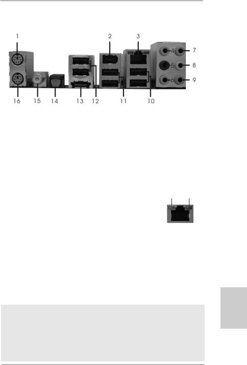
ASRock WiFi_SPDIF I/O
1 |
PS/2 |
Mouse Port (Green) |
9 |
Microphone (Pink) |
|
2 |
IEEE |
1394 Port |
10 |
USB 2.0 Ports (USB01) |
|
* 3 |
LAN RJ-45 Port |
11 |
USB 2.0 Ports (USB23) |
||
4 |
Side |
Speaker |
(Gray) |
12 |
USB 2.0 Ports (USB45) |
5 |
Rear |
Speaker |
(Black) |
13 |
eSATAII Port |
6 |
Central / Bass |
(Orange) |
14 |
Optical SPDIF Out Port |
|
7 |
Line |
In (Light Blue) |
15 Coaxial SPDIF Out Port |
||
**8 |
Front |
Speaker |
(Lime) |
16 |
PS/2 Keyboard Port (Purple) |
*There are two LED next to the LAN port. Please refer to the table below for the LAN port LED indications.
LAN Port LED Indications
|
SPEED LED |
|
Activity/Link LED |
SPEED |
ACT/LINK |
|
|
|
LED |
LED |
|||
Status |
Description |
|
Status |
Description |
|
|
Off |
10Mbps connection |
|
Off |
No link |
|
|
Orange |
100Mbps connection |
|
Orange |
Linked |
|
|
Green |
1Gbps connection |
|
Blinking |
Data Activity |
LAN Port |
|
|
|
|
|
|
||
**If you use 2-channel speaker, please connect the speaker’s plug into “Front Speaker Jack”. See the table below for connection details in accordance with the type of speaker you use.
TABLE for Audio Output Connection
Audio Output Channels |
Front Speaker |
Rear Speaker |
Central / Bass |
Side Speaker |
|
(No. 8) |
(No. 5) |
(No. 6) |
(No. 4) |
2 |
V |
-- |
-- |
-- |
4 |
V |
-- |
-- |
V |
6 |
V |
-- |
V |
V |
8 |
V |
V |
V |
V |
To enable Multi-Streaming function, you need to connect a front panel audio cable to the front panel audio header. After restarting your computer, you will find “Mixer” tool on your system. Please select “Mixer ToolBox”  , click “Enable playback multi-streaming”, and click
“ok”. Choose “2CH”, “4CH”, “6CH”, or “8CH” and then you are allowed to select “Realtek HDA Primary output” to use Rear Speaker, Central/Bass, and Front Speaker, or select “Realtek HDA Audio 2nd output” to use front panel audio.
3
English
ASRock K10N780SLIX3-WiFi Motherboard
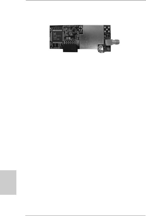
ASRock WiFi-802.11g Module Specifications
hsilgnE
4
ASRock WiFi-802.11g module is an easy-to-use wireless local area network (WLAN) adapter to support WiFi+AP function. With ASRock WiFi-802.11g module, you can easily create a wireless environment and enjoy the convenience of wireless network connectivity. Therefore, from anywhere within the signal range, you will be able to play LAN games, connect to the internet, access and share printers, and make Internet phone calls easily.
Standard |
- IEEE 802.11g |
Data Rate |
- 6, 9, 12, 18, 24, 36, 48, 54Mbps |
Security |
- Access Point mode (AP mode): WEP, WPA |
Network |
- Access Point mode (AP mode) |
Architecture Types |
- Station mode: Infrastructure mode and Ad-Hoc mode |
Frequency Band |
- 2.4~2.5GHz |
Operating Range |
- Indoor: 80ft (30m) |
|
Outdoor: 200ft (60m) |
|
* The range varies in different environments |
Number of |
- up to 16 stations |
Connected Devices |
|
(AP Mode) |
|
Antenna |
- ASRock WiFi-802.11g omni-directional antenna |
LED |
- Green data transmission (AIR) LED |
Support OS |
- Windows® XP / XP 64-bit / VistaTM / VistaTM 64-bit |
Compatibility |
- Full compatible with IEEE 802.11g standard products |
Software Support |
- ASRock WiFi-802.11g Wizard |
If you want to start to use ASRock WiFi-802.11g module on this motherboard, please carefully read “ASRock WiFi-802.11g Module Operation Guide” in the package for the detailed introduction and operation procedures. You can also read the document in the following path of ASRock motherboard support CD:
..\ ASRock WiFi-802.11g \ Vista64_Vista_XP64_XP
ASRock K10N780SLIX3-WiFi Motherboard

1. Introduction
Thank you for purchasing ASRock K10N780SLIX3-WiFi motherboard, a reliable motherboard produced under ASRock’s consistently stringent quality control. It delivers excellent performance with robust design conforming to ASRock’s commitment to quality and endurance.
This Quick Installation Guide contains introduction of the motherboard and step-by- step installation guide. More detailed information of the motherboard can be found in the user manual presented in the Support CD.
Because the motherboard specifications and the BIOS software might be updated, the content of this manual will be subject to change without notice. In case any modifications of this manual occur, the updated version will be available on ASRock website without further notice. You may find the latest VGA cards and CPU support lists on ASRock website as well. ASRock website http://www.asrock.com
If you require technical support related to this motherboard, please visit our website for specific information about the model you are using. www.asrock.com/support/index.asp
1.1 Package Contents
ASRock K10N780SLIX3-WiFi Motherboard
(ATX Form Factor: 12.0-in x 9.6-in, 30.5 cm x 24.4 cm) ASRock K10N780SLIX3-WiFi Quick Installation Guide ASRock K10N780SLIX3-WiFi Support CD
ASRock WiFi-802.11g Module Operation Guide
Motherboard Accessories
One ASRock SLI Bridge
One ASRock 3-Way SLI Bridge
One ASRock SLI/XFire Switch Card
One 80-conductor Ultra ATA 66/100/133 IDE Ribbon Cable
One Ribbon Cable for a 3.5-in Floppy Drive
Four Serial ATA (SATA) Data Cables (Optional)
One Serial ATA (SATA) HDD Power Cable (Optional)
One HDMI_SPDIF Cable (Optional)
One “ASRock WiFi_SPDIF I/O” I/O Panel Shield
WiFi Accessories
One ASRock WiFi-802.11g Module
One Antenna
5
English
ASRock K10N780SLIX3-WiFi Motherboard

hsilgnE
6
1.2 Specifications
Platform |
- ATX Form Factor: 12.0-in x 9.6-in, 30.5 cm x 24.4 cm |
|
- All Solid Capacitor design |
CPU |
- Support for Socket AM2+ / AM2 processors: AMD PhenomTM |
|
FX / Phenom / Athlon 64 FX / Athlon 64 X2 Dual-Core / Athlon |
|
X2 Dual-Core / Athlon 64 / Sempron processor |
|
- AMD LIVE!TM Ready |
|
- Supports AMD’s Cool ‘n’ QuietTM Technology |
|
- FSB 2600 MHz (5.2 GT/s) (see CAUTION 1) |
|
- Supports Untied Overclocking Technology (see CAUTION 2) |
|
- Supports Hyper-Transport 3.0 (HT 3.0) Technology |
|
|
Chipset |
- NVIDIA® nForce 780a SLI |
Memory |
- Dual Channel DDR2 Memory Technology (see CAUTION 3) |
|
- 4 x DDR2 DIMM slots |
|
- SupportDDR2 1066/800/667/533 non-ECC, un-buffered memory |
|
(see CAUTION 4) |
|
- Max. capacity of system memory: 8GB (see CAUTION 5) |
Expansion Slot |
- 3 x PCI Express 2.0 x16 slots |
|
(green @ x16 mode, blue @ x8 mode) |
|
- 1 x PCI Express x1 slot |
|
- 2 x PCI slots |
|
- Supports NVIDIA® SLITM and 3-Way SLITM (see CAUTION 6) |
|
- Supports NVIDIA® Hybrid SLITM GeForce® Boost feature |
|
(see CAUTION 7) |
Audio |
- 7.1 CH Windows® VistaTM Premium Level HD Audio with |
|
Content Protection |
|
- DAC with 110dB dynamic range (ALC890 Audio Codec) |
|
- DTS (Digital Theater Systems) support (see CAUTION 8) |
LAN |
- Gigabit LAN 10/100/1000 Mb/s |
|
- Giga PHY Realtek RTL8211B |
|
- Supports Wake-On-LAN |
Wireless LAN |
- ASRock WiFi-802.11g module |
|
- 54Mbps IEEE 802.11g / 11Mbps IEEE 802.11b |
|
- Supports Software Access Point mode (AP mode) and |
|
Station mode (Infrastructure mode and Ad-hoc mode) |
Rear Panel I/O |
ASRock WiFi_SPDIF I/O |
|
- 1 x PS/2 Mouse Port |
|
- 1 x PS/2 Keyboard Port |
|
- 1 x Coaxial SPDIF Out Port |
|
- 1 x Optical SPDIF Out Port |
ASRock K10N780SLIX3-WiFi Motherboard

|
- 6 x Ready-to-Use USB 2.0 Ports |
|
- 1 x eSATAII Port |
|
- 1 x RJ-45 LAN Port with LED (ACT/LINK LED and SPEED LED) |
|
- 1 x IEEE 1394 Port |
|
- HDAudio Jack: Side Speaker/Rear Speaker/Central/Bass/ |
|
Line in/Front Speaker/Microphone (see CAUTION 9) |
Connector |
- 6 x SATAII 3.0Gb/s connectors, support RAID (RAID 0, RAID 1, |
|
RAID 0+1, JBOD and RAID 5), NCQ, AHCI and “Hot Plug” |
|
functions (see CAUTION 10) |
|
- 1 x eSATAII 3.0Gb/s connector (shared with 1 SATAII |
|
connector) (see CAUTION 11) |
|
- 1 x ATA133 IDE connector (supports 2 x IDE devices) |
|
- 1 x Floppy connector |
|
- 1 x DeskExpress Hot Plug Detection header |
|
- 1 x COM port header |
|
- 1 x HDMI_SPDIF header |
|
- 1 x IEEE 1394 header |
|
- CPU/Chassis FAN connector |
|
- 24 pin ATX power connector |
|
- 8 pin 12V power connector |
|
- CD in header |
|
- Front panel audio header |
|
- 2 x USB 2.0 headers (support 4 USB 2.0 ports) |
|
(see CAUTION 12) |
|
- 1 x WiFi/E header (see CAUTION 13) |
BIOS Feature |
- 8Mb AMI BIOS |
|
- AMI Legal BIOS |
|
- Supports “Plug and Play” |
|
- ACPI 1.1 Compliance Wake Up Events |
|
- Supports jumperfree |
|
- AMBIOS 2.3.1 Support |
|
- CPU, DRAM, Chipset Core, PCIE Bridge Voltage |
|
Multi-adjustment |
Support CD |
- Drivers, Utilities, AntiVirus Software (Trial Version) |
Unique Feature |
- ASRock OC Tuner (see CAUTION 14) |
|
- Intelligent Energy Saver (see CAUTION 15) |
|
- Hybrid Booster: |
|
- CPU Frequency Stepless Control (see CAUTION 16) |
|
- ASRock U-COP (see CAUTION 17) |
|
- Boot Failure Guard (B.F.G.) |
|
- ASRock AM2 Boost: ASRock Patented Technology to boost |
|
memory performance up to 12.5% (see CAUTION 18) |
7
English
ASRock K10N780SLIX3-WiFi Motherboard

hsilgnE
Hardware |
- CPU Temperature Sensing |
Monitor |
- Chassis Temperature Sensing |
|
- CPU Fan Tachometer |
|
- Chassis Fan Tachometer |
|
- CPU Quiet Fan |
|
- Voltage Monitoring: +12V, +5V, +3.3V, CPU Vcore |
OS |
- Microsoft® Windows® XP / XP Media Center / XP 64-bit / VistaTM |
|
/ VistaTM 64-bit compliant |
Certifications |
- FCC, CE, WHQL |
* For detailed product information, please visit our website: http://www.asrock.com
WARNING
Please realize that there is a certain risk involved with overclocking, including adjusting the setting in the BIOS, applying Untied Overclocking Technology, or using the third-party overclocking tools. Overclocking may affect your system stability, or even cause damage to the components and devices of your system. It should be done at your own risk and expense. We are not responsible for possible damage caused by overclocking.
CAUTION!
1.If you install AM2 CPU on this motherbord, the system bus speed will be HT1.0 (2000 MT/s). If you install AM2+ CPU on this motherbord, the system bus speed will be HT3.0 (up to 5200 MT/s), and the HT Link frequency depends on the ability of the AM2+ CPU you adopt. Please refer to the CPU support list on our website for more information.
ASRock website http://www.asrock.com
2.This motherboard supports Untied Overclocking Technology. Please read “Untied Overclocking Technology” on page 37 for details.
3.This motherboard supports Dual Channel Memory Technology. Before you implement Dual Channel Memory Technology, make sure to read the installation guide of memory modules on page 14 for proper installation.
4.Whether 1066MHz memory speed is supported depends on the AM2+ CPU you adopt. If you want to adopt DDR2 1066 memory module on this motherboard, please refer to the memory support list on our website for the compatible memory modules.
ASRock website http://www.asrock.com
5.Due to the operating system limitation, the actual memory size may be less than 4GB for the reservation for system usage under Windows® XP and Windows® VistaTM. For Windows® XP 64-bit and Windows® VistaTM 64-bit with 64-bit CPU, there is no such limitation.
6.This motherboard supports NVIDIA® SLITM and 3-Way SLITM technology. If you want to use SLITM function, please follow the instructions on page 18 and 19 to reverse the direction of ASRock SLI/XFire Switch Card in advance. To use SLITM function, please install two identical SLITM graphics cards on
8
ASRock K10N780SLIX3-WiFi Motherboard

PCIE1 and PCIE2 slots. To use 3-Way SLITM function, please install three identical 3-Way SLITM support graphics cards on PCIE1, PCIE2 and PCIE4 slots. For the information of the compatible SLITM and 3-Way SLITM PCI Express VGA cards, please refer to page 11. For the proper installation of PCI Express VGA card, please refer to the installation guide on page 16.
7.Hybrid SLITM feature should depend on the driver from NVIDIA® and it may be updated in the future. As long as we have the latest Hybrid SLITM driver, we will update it to our website. Please visit our website for the updated Hybrid SLITM driver in the future. For the operation procedures, please refer to “Hybrid SLITM Operation Guide” on page 24.
8.DTS (Digital Theater Systems) is a multi-channel digital surround sound format. To enable DTS function, you need to adjust the settings after audio driver installation. Please refer to “DTS Operation Guide” on page 35 for details.
9.For microphone input, this motherboard supports both stereo and mono modes. For audio output, this motherboard supports 2-channel, 4-channel, 6-channel, and 8-channel modes. Please check the table on page 3 for proper connection.
10.Before installing SATAII hard disk to SATAII connector, please read the “SATAII Hard Disk Setup Guide” on page 40 of “User Manual” in the support CD to adjust your SATAII hard disk drive to SATAII mode. You can also connect SATA hard disk to SATAII connector directly.
11.This motherboard supports eSATAII interface, the external SATAII specification. Please read “eSATAII Interface Introduction” on page 30 for details about eSATAII and eSATAII installation procedures.
12.Power Management for USB 2.0 works fine under Microsoft® Windows® VistaTM 64-bit / VistaTM / XP 64-bit / XP SP1 or SP2.
13.WiFi/E header supports WiFi+AP function with ASRock WiFi-802.11g or WiFi-802.11n module, an easy-to-use wireless local area network (WLAN) adapter. It allows you to create a wireless environment and enjoy the convenience of wireless network connectivity.
14.It is a user-friendly ASRock overclocking tool which allows you to surveil your system by hardware monitor function and overclock your hardware devices to get the best system performance under Windows® environment. Please visit our website for the operation procedures of ASRock OC Tuner. ASRock website: http://www.asrock.com
15.Featuring an advanced proprietary hardware and software design, Intelligent Energy Saver is a revolutionary technology that delivers unparalleled power savings. The voltage regulator can reduce the number of output phases to improve efficiency when the CPU cores are idle. In other words, it is able to provide exceptional power saving and improve power efficiency without sacrificing computing performance. To use Intelligent Energy Saver function, please enable Cool ‘n’ Quiet option in the BIOS setup in advance. Please visit our website for the operation procedures of Intelligent Energy Saver.
ASRock website: http://www.asrock.com
English
9
ASRock K10N780SLIX3-WiFi Motherboard

16.Although this motherboard offers stepless control, it is not recommended to perform over-clocking. Frequencies other than the recommended CPU bus frequencies may cause the instability of the system or damage the CPU.
17.While CPU overheat is detected, the system will automatically shutdown. Before you resume the system, please check if the CPU fan on the motherboard functions properly and unplug the power cord, then plug it back again. To improve heat dissipation, remember to spray thermal grease between the CPU and the heatsink when you install the PC system.
18.This motherboard supports ASRock AM2 Boost overclocking technology for AM2 CPU. If you enable this function in the BIOS setup, the memory performance will improve up to 12.5%, but the effect still depends on the AM2 CPU you adopt. Enabling this function will overclock the chipset/CPU reference clock. However, we can not guarantee the system stability for all CPU/DRAM configurations. If your system is unstable after AM2 Boost function is enabled, it may not be applicative to your system. You may choose to disable this function for keeping the stability of your system.
1.3 Minimum Hardware Requirement Table for Windows® VistaTM Premium 2008 and Basic Logo
For system integrators and users who purchase this motherboard and
plan to submit Windows® VistaTM Premium 2008 and Basic logo, please follow below table for minimum hardware requirement.
CPU |
Sempron 2800+ |
Memory |
1GB system memory (Premium) |
|
512MB system memory (Basic) |
VGA |
DX10 with WDDM Driver |
|
with 128bit VGA memory (Premium) |
|
with 64bit VGA memory (Basic) |
*After June 1, 2008, all Windows® VistaTM systems are required to meet above minimum hardware requirements in order to qualify for Windows® VistaTM Premium 2008 logo.
hsilgnE
1 0
ASRock K10N780SLIX3-WiFi Motherboard
1.4 Supported PCI Express VGA Card List for SLITM Mode
(for Windows® XP / XP 64-bit / VistaTM / VistaTM 64-bit only)
Graphics Chip |
Model Name |
Chipset Name |
Driver |
Vendor |
|
|
|
NVIDIA |
ASUS Extreme N7800GTX/2DHTV |
GeForce 7800GTX |
169.21 |
|
Chaintech GES96GT-A1512P |
GeForce 9600GT |
174.74 |
|
GIGABYTE GV-NX85T256H |
GeForce 8500GT |
169.21 |
|
Gigabyte GV-NX88T256H |
GeForce 8800GT |
169.21 |
|
Gigabyte GV-NX88S512H-B |
GeForce 8800GTS |
169.21 |
|
LEADTEK PX8800 GTX TDH |
GeForce 8800GTX |
169.21 |
|
MSI NX8600GT-T2D256E |
GeForce 8600GT |
169.21 |
|
SPARKLE SF-PX98GX221024D3- |
GeForce 9800GX2 |
174.74 |
|
NHM * |
|
|
* This graphics card can support 2-Way SLITM (with 1 card) or 4-Way SLITM (with 2 cards).
* For the latest updates of the supported PCI Express VGA card list for SLITM Mode, please visit our website for details.
ASRock website: http://www.asrock.com/support/index.htm
1.5 Supported PCI Express VGA Card List for 3-Way SLITM Mode
(for Windows® VistaTM / VistaTM 64-bit only)
Graphics Chip |
Model Name |
Chipset Name |
Driver |
Vendor |
|
|
|
NVIDIA |
LEADTEK PX8800 GTX TDH |
GeForce 8800GTX |
169.21 |
|
LEADTEK PX9800GTX |
GeForce 9800GTX |
174.74 |
|
|
|
|
*Currently, only NVIDIA SLI-Ready GeForce 8800Ultra, GeForce 8800GTX and GeForce 9800GTX graphics cards support 3-Way SLITM Mode. For the latest updates of the supported PCI Express VGA card list for 3-Way SLITM Mode, please visit our website for details.
ASRock website: http://www.asrock.com/support/index.htm
English
1 1
ASRock K10N780SLIX3-WiFi Motherboard
2. Installation
This is an ATX form factor (12.0-in x 9.6-in, 30.5 cm x 24.4 cm) motherboard.
Before you install the motherboard, study the configuration of your chassis to ensure that the motherboard fits into it.
Pre-installation Precautions
Take note of the following precautions before you install motherboard components or change any motherboard settings.
Before you install or remove any component, ensure that the power is switched off or the power cord is detached from the power supply. Failure to do so may cause severe damage to the motherboard, peripherals, and/or components.
1.Unplug the power cord from the wall socket before touching any component.
2.To avoid damaging the motherboard components due to static electricity, NEVER place your motherboard directly on the carpet or the like. Also remember to use a grounded wrist strap or touch a safety grounded object before you handle components.
3.Hold components by the edges and do not touch the ICs.
4.Whenever you uninstall any component, place it on a grounded antistatic pad or in the bag that comes with the component.
5.When placing screws into the screw holes to secure the motherboard to the chassis, please do not over-tighten the screws! Doing so may damage the motherboard.
hsilgnE
1 2
ASRock K10N780SLIX3-WiFi Motherboard
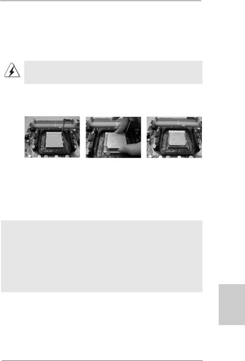
2.1CPU Installation
Step 1. Unlock the socket by lifting the lever up to a 90o angle.
Step 2. Position the CPU directly above the socket such that the CPU corner with the golden triangle matches the socket corner with a small triangle.
Step 3. Carefully insert the CPU into the socket until it fits in place.
The CPU fits only in one correct orientation. DO NOT force the CPU into the socket to avoid bending of the pins.
Step 4. When the CPU is in place, press it firmly on the socket while you push down the socket lever to secure the CPU. The lever clicks on the side tab to indicate that it is locked.
Lever 90°Up |
|
|
|
CPU Golden Triangle |
|
|
SocketCorner |
|
|
Small Triangle |
|
STEP 1: |
STEP 2 / STEP 3: |
STEP 4: |
Lift Up The Socket Lever |
Match The CPU Golden Triangle |
Push Down And Lock |
|
To The Socket Corner Small |
The Socket Lever |
|
Triangle |
|
2.2 Installation of CPU Fan and Heatsink
After you install the CPU into this motherboard, it is necessary to install a larger heatsink and cooling fan to dissipate heat. You also need to spray thermal grease between the CPU and the heatsink to improve heat dissipation. Make sure that the CPU and the heatsink are securely fastened and in good contact with each other. Then connect the CPU fan to the CPU FAN connector (CPU_FAN1, see Page 2, No. 5). For proper installation, please kindly refer to the instruction manuals of the CPU fan and the heatsink.
English
1 3
ASRock K10N780SLIX3-WiFi Motherboard
2.3 Installation of Memory Modules (DIMM)
This motherboard provides four 240-pin DDR2 (Double Data Rate 2) DIMM slots, and supports Dual Channel Memory Technology. For dual channel configuration, you always need to install identical (the same brand, speed, size and chip-type) DDR2 DIMM pair in the slots of the same color. In other words, you have to install identical DDR2 DIMM pair in Dual Channel A (DDRII_1 and DDRII_2; Yellow slots; see p.2 No.6) or identical DDR2 DIMM pair in Dual Channel B (DDRII_3 and DDRII_4; Orange slots; see p.2 No.7), so that Dual Channel Memory Technology can be activated. This motherboard also allows you to install four DDR2 DIMMs for dual channel configuration, and please install identical DDR2 DIMMs in all four slots. You may refer to the Dual Channel Memory Configuration Table below.
hsilgnE
1 4
Dual Channel Memory Configurations
|
DDRII_1 |
DDRII_2 |
DDRII_3 |
DDRII_4 |
|
(Yellow Slot) |
(Yellow Slot) |
(Orange Slot) |
(Orange Slot) |
(1) |
Populated |
Populated |
- |
- |
(2) |
- |
- |
Populated |
Populated |
(3)* |
Populated |
Populated |
Populated |
Populated |
|
|
|
|
|
*For the configuration (3), please install identical DDR2 DIMMs in all four slots.
1.If you want to install two memory modules, for optimal compatibility and reliability, it is recommended to install them in the slots of the same color. In other words, install them either in the set of yellow slots (DDRII_1 and DDRII_2), or in the set of orange slots (DDRII_3 and DDRII_4).
2.If only one memory module or three memory modules are installed in the DDR2 DIMM slots on this motherboard, it is unable to activate the Dual Channel Memory Technology.
3.If a pair of memory modules is NOT installed in the same Dual Channel, for example, installing a pair of memory modules in DDRII_1 and DDRII_3, it is unable to activate the Dual Channel Memory Technology .
4.It is not allowed to install a DDR memory module into DDR2 slot; otherwise, this motherboard and DIMM may be damaged.
ASRock K10N780SLIX3-WiFi Motherboard
Installing a DIMM
Please make sure to disconnect power supply before adding or removing DIMMs or the system components.
Step 1. Unlock a DIMM slot by pressing the retaining clips outward.
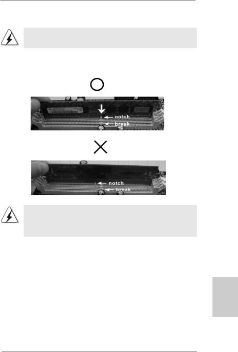
Step 2. Align a DIMM on the slot such that the notch on the DIMM matches the break on the slot.
The DIMM only fits in one correct orientation. It will cause permanent damage to the motherboard and the DIMM if you force the DIMM into the slot at incorrect orientation.
Step 3. Firmly insert the DIMM into the slot until the retaining clips at both ends fully snap back in place and the DIMM is properly seated.
English
1 5
ASRock K10N780SLIX3-WiFi Motherboard
2.4 Expansion Slots (PCI and PCI Express Slots)
There are 2 PCI slots and 4 PCI Express slots on this motherboard.
PCI Slots: PCI slots are used to install expansion cards that have the 32-bit PCI interface.
PCIE Slots:
PCIE1 / PCIE2 (PCIE x16 slot; Green) is used for PCI Express x16 lane width graphics cards, or used to install PCI Express graphics cards to support SLITM function.
PCIE3 (PCIE x1 slot; White) is used for PCI Express cards with x1 lane width cards, such as Gigabit LAN card, SATA2 card, etc.
PCIE4 (PCIE x16 slot; Blue) is used for PCI Express x1 lane width cards, such as Gigabit LAN card, SATA2 card, and ASRock PCIE_DE card, or used to install PCI Express graphics cards to support 3-Way SLITM function.
PCIE1 / PCIE2 / PCIE4 / SLI/XFire Switch Card Retention Slot
|
|
|
|
Configurations |
|
|
|
|
|
|
|
|
|
|
|
|
PCIE1 |
PCIE2 |
PCIE4 |
SLI/XFire Switch Card |
|
|
|
(Green) |
(Green) |
(Blue) |
Retention Slot |
|
|
Dual Graphics Cards |
PCIE x16 |
PCIE x16 |
PCIE x1 |
|
|
|
in SLITM Mode |
|
|
|
|
|
|
|
|
|
|
|
|
|
Triple Graphics Cards |
PCIE x16 |
PCIE x8 |
PCIE x8 |
|
|
|
in 3-Way SLITM Mode |
|
|
|
|
|
|
|
|
|
|
(Default) |
hsilgnE |
|
|
|
|
|
|
|
|
|
|
|
|
|
|
|
|
|
|
|
|
|
|
|
|
|
|
|
1 6
ASRock K10N780SLIX3-WiFi Motherboard
1.This motherboard supports NVIDIA® SLITM and 3-Way SLITM technology. If you want to use SLITM function, please install two identical SLITM graphics cards on PCIE1 and PCIE2 slots. If you want to use 3-Way SLITM function, please install three identical 3-Way SLITM support graphics cards on PCIE1, PCIE2 and PCIE4 slots.
2.For the information of the compatible SLITM and 3-Way SLITM Mode PCI Express VGA cards, please refer to page 11. For the operation procedures of SLITM and 3-Way SLITM Mode, please refer to page 18.
3.If you plan to install only one PCI Express VGA card on this motherboard, it is suggested to install it on PCIE1 slot (Green). However, if you install ASRock WiFi-802.11g module on this motherboard and it is collided with the PCI Express VGA card on PCIE1 slot, you may install the PCI Express VGA card on PCIE2 slot; under this condition, please switch ASRock SLI/XFire Switch Card to x16 / x1 mode in advance.
4.If you want to use ASRock DeskExpress function on this motherboard, please install ASRock PCIE_DE card on PCIE4 slot (Blue), and switch ASRock SLI/XFire Switch Card to x16 / x1 mode. Please do not remove or lose ASRock SLI/XFire Switch Card when it is still in working condition.
Installing an expansion card
Step 1. Before installing the expansion card, please make sure that the power supply is switched off or the power cord is unplugged. Please read the documentation of the expansion card and make necessary hardware settings for the card before you start the installation.
Step 2. Remove the system unit cover (if your motherboard is already installed in a chassis).
Step 3. Remove the bracket facing the slot that you intend to use. Keep the screws for later use.
Step 4. Align the card connector with the slot and press firmly until the card is completely seated on the slot.
Step 5. Fasten the card to the chassis with screws. Step 6. Replace the system cover.
English
1 7
ASRock K10N780SLIX3-WiFi Motherboard
2.5 SLITM and 3-Way SLITM Operation Guide
This motherboard supports NVIDIA® SLITM and 3-Way SLITM (Scalable Link Interface) technology that allows you to install up to three identical PCI Express x16 graphics cards. Currently, NVIDIA® SLITM technology supports Windows® XP, XP 64-bit, VistaTM and VistaTM 64-bit OS. NVIDIA® 3-Way SLITM technology supports Windows® VistaTM and VistaTM 64-bit OS. Please follow the installation procedures in this section.
Requirements
1.For SLITM technology, you should have two identical SLITM-ready graphics cards that are NVIDIA® certified. For 3-Way SLITM technology, you should have three identical 3-Way SLITM-ready graphics cards that are NVIDIA®
certified.
2.Make sure that your graphics card driver supports the NVIDIA® SLITM technology. Download the latest driver from the NVIDIA® website
(www.nvidia.com).
3.Make sure that your power supply unit (PSU) can provide at least the minimum power required by your system. It is recommended to use
NVIDIA® certified PSU. Please refer to NVIDIA® website for details.
2.5.1 Graphics Card Setup
2.5.1.1 Installing Two SLITM-Ready Graphics Cards
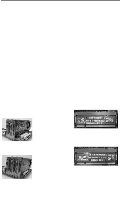
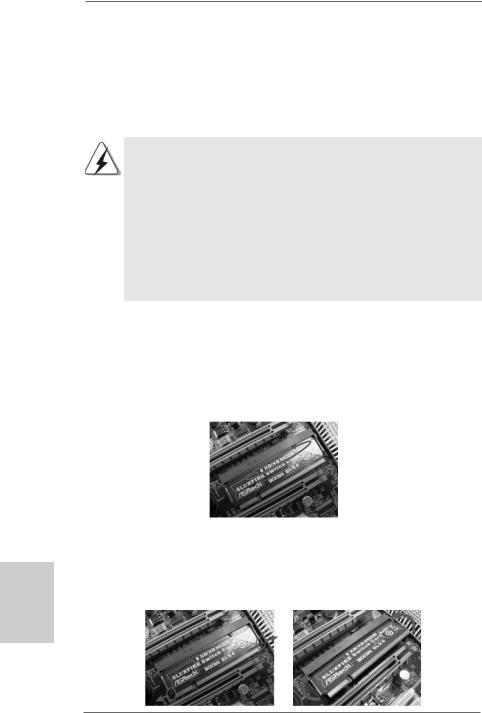
Step 1. There is one ASRock SLI/XFire Switch Card factory-mounted on this motherboard. This card served as a switch between the default mode (x8 / x8) and x16 / x1 mode. ASRock SLI/XFire Switch Card is factory-mounted with its default mode (x8 / x8) side toward the retention slot base.
hsilgnE
Step 2. To change it to SLI Mode, you need to reverse the direction of ASRock SLI/ XFire Switch Card. Please simultaneously pull open both the retention arms that hold the card in position. The card itself will spring away from the retention slot. Take it out gently by holding its edges, and keep away from touching the connectors (Golden Fingers).
1 8
ASRock K10N780SLIX3-WiFi Motherboard
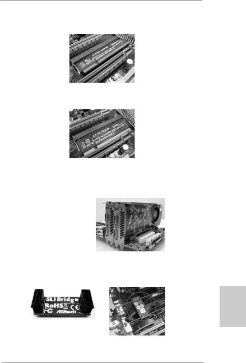
Step 3. Reverse the card direction so as to have the “X16 MODE” wording side toward the retention slot base. Insert the card into the bottom of the base.
Step 4. Push the card down into the retention slot till both the retention arms firmly hold the card into position. Also, keep away from touching the connectors (Golden Fingers).
Step 5. Install the identical SLITM-ready graphics cards that are NVIDIA® certified because different types of graphics cards will not work together properly. (Even the GPU chips version shall be the same.) Insert one graphics card into PCIE1 slot and another graphics card to PCIE2 slot. Make sure that the cards are properly seated on the slots.
Step 6. If required, connect the auxiliary power source to the PCI Express graphics cards.
Step 7. Align and insert the SLI Bridge to the goldfingers on each graphics card. Make sure that the SLI Bridge is firmly in place.
English
Step 8. Connect a VGA cable or a DVI cable to the monitor connector or the DVI connector of the graphics card that is inserted to PCIE1 slot.
1 9
ASRock K10N780SLIX3-WiFi Motherboard
hsilgnE
2.5.1.2 Installing Three SLITM-Ready Graphics Cards
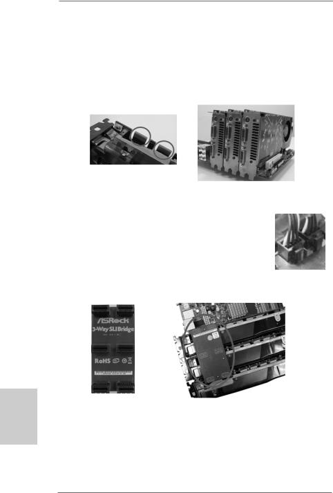
Step 1. Install the identical 3-Way SLITM-ready graphics cards that are NVIDIA® certified because different types of graphics cards will not work together properly. (Even the GPU chips version shall be the same.) Each graphics card should have two goldfingers for the 3-Way SLI Bridge connector. Insert one graphics card into PCIE1 slot, another graphics card to PCIE2 slot, and the other graphics card to PCIE4 slot. Make sure that the cards are properly seated on the slots.
Two Goldfingers
Step 2. Connect the auxiliary power source to the PCI Express graphics card. Please make sure that both power connectors on the PCI Express graphics card are connected. Repeat this step on the three graphics cards.
Step 3. Align and insert the 3-Way SLI Bridge to the goldfingers on each graphics card. Make sure that the 3-Way SLI Bridge is firmly in place.
Step 4. Connect a VGA cable or a DVI cable to the monitor connector or the DVI connector of the graphics card that is inserted to PCIE1 slot.
2 0
ASRock K10N780SLIX3-WiFi Motherboard
2.5.2 Driver Installation and Setup
Install the graphics card drivers to your system. After that, you can enable the MultiGraphics Processing Unit (GPU) feature in the NVIDIA® nView system tray utility. Please follow the below procedures to enable the multi-GPU feature.
For Windows® XP / XP 64-bit OS: (For SLITM mode only)
A.Click the NVIDIA Settings icon on your Windows® taskbar.
B.From the pop-up menu, select nView Desktop Manager, and then click nView Properties.
C.From the nView Desktop Manager window, select the Desktop Management tab.
D.Click Properties to display the Display Properties dialog box.
English
2 1
ASRock K10N780SLIX3-WiFi Motherboard
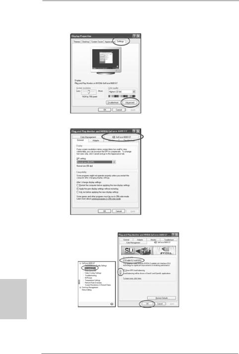
E.From the Display Properties dialog box, select the Settings tab then click
Advanced.
F. Select the NVIDIA GeForce tab.
G.Click the slider to display the following screen, then select the SLI multi-GPU item.
hsilgnE
H.Click the Enable SLI multi-GPU check box.
I.Click OK when done.
2 2
ASRock K10N780SLIX3-WiFi Motherboard
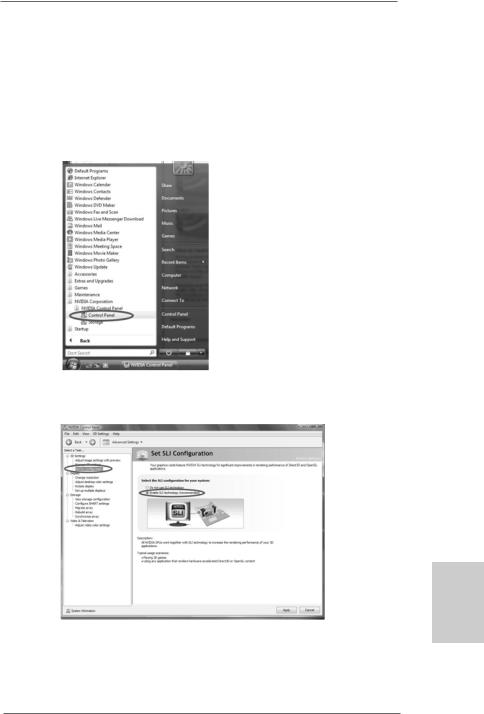
For Windows® VistaTM / VistaTM 64-bit OS: (For SLITM and 3-way SLITM mode)
A.Click the Start icon on your Windows taskbar.
B.From the pop-up menu, select All Programs, and then click NVIDIA Corporation.
C.Select NVIDIA Control Panel tab.
D.Select Control Panel tab.
E.From the pop-up menu, select Set SLI configuration, and click Apply. Then choose Enable SLI technology (recommended).
English
*SLITM appearing here is a registered trademark of NVIDIA® Technologies Inc., and is used only for identification or explanation and to the owners’ benefit, without intent to infringe.
2 3
ASRock K10N780SLIX3-WiFi Motherboard
hsilgnE
2.6 Hybrid SLITM Operation Guide
This motherboard supports NVIDIA® Hybrid SLITM feature. Hybrid SLITM technology, based on NVIDIA®’ s industry-leading SLITM technology, delivers multi-GPU (graphics processing unit) benefits when an NVIDIA® motherboard GPU is combined with an NVIDIA® discrete GPU. Hybrid SLITM technology today includes two primary features: GeForce® Boost and HybridPowerTM. This motherboard is compatible with GeForce® Boost feature in Hybrid SLITM, which can increase graphics performance. Currently, NVIDIA® Hybrid SLITM Technology is only supported with Windows® VistaTM OS, and is not available with other OS. Please visit our website for the driver update in the future. For the compatible PCI Express graphics cards and the installation procedures, please refer to page 27 of “User Manual” in the support CD.
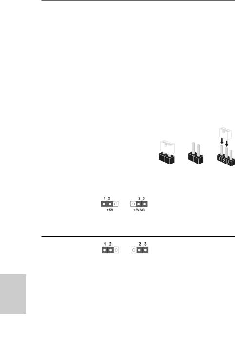
2.7 Jumpers Setup
The illustration shows how jumpers are setup. When the jumper cap is placed on pins, the jumper is “Short”. If no jumper cap is placed on pins, the jumper is “Open”. The illustration shows a 3-pin jumper whose pin1
and pin2 are “Short” when jumper cap is Short Open placed on these 2 pins.
Jumper |
Setting |
PS2_USB_PW1 |
Short pin2, pin3 to enable |
(see p.2, No. 1) |
+5VSB (standby) for PS/2 or |
|
USB wake up events. |
Note: To select +5VSB, it requires 2 Amp and higher standby current provided by power supply.
Clear CMOS Jumper
(CLRCMOS1)
(see p.2, No. 13) Default Clear CMOS
Note: CLRCMOS1 allows you to clear the data in CMOS. The data in CMOS includes system setup information such as system password, date, time, and system setup parameters. To clear and reset the system parameters to default setup, please turn off the computer and unplug the power cord from the power supply. After waiting for 15 seconds, use a jumper cap to short pin2 and pin3 on CLRCMOS1 for 5 seconds. However, please do not clear the CMOS right after you update the BIOS. If you need to clear the CMOS when you just finish updating the BIOS, you must boot up the system first, and then shut it down before you do the clear-CMOS action.
2 4
ASRock K10N780SLIX3-WiFi Motherboard
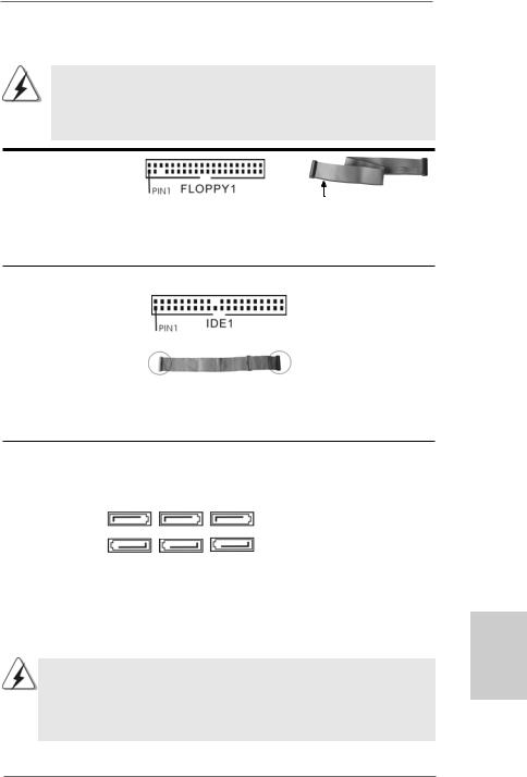
2.8 Onboard Headers and Connectors
Onboard headers and connectors are NOT jumpers. Do NOT place jumper caps over these headers and connectors. Placing jumper caps over the headers and connectors will cause permanent damage of the motherboard!
•
Floppy Connector
(33-pin FLOPPY1)
(see p.2, No. 28)
the red-striped side to
Pin1
Note: Make sure the red-striped side of the cable is plugged into Pin1 side of the connector.
Primary IDE connector (Blue)
(39-pin IDE1, see p.2, No. 9)
connect the blue end |
connect the black end |
to the motherboard |
to the IDE devices |
80-conductor ATA 66/100/133 cable
Note: Please refer to the instruction of your IDE device vendor for the details.
Serial ATA II Connectors
(SATAII_1 (PORT0): |
|
|
|
|
see |
p.2, No. 23) |
SATAII_1 |
SATAII_3 |
SATAII_5 |
(SATAII_2 (PORT1): |
(PORT0) |
(PORT2) |
(PORT4) |
|
|
|
|
||
see |
p.2, No. 20) |
|
|
|
(SATAII_3 (PORT2): |
|
|
|
|
see |
p.2, No. 14) |
SATAII_2 |
SATAII_4 |
SATAII_6 |
(SATAII_4 (PORT3): |
(PORT1) |
(PORT3) |
(PORT5) |
|
see |
p.2, No. 18) |
|
|
|
(SATAII_5 (PORT4): |
|
|
|
|
see |
p.2, No. 15) |
|
|
|
(SATAII_6 (PORT5): |
|
|
|
|
see |
p.2, No. 16) |
|
|
|
These six Serial ATAII (SATAII) connectors support SATA data cables for internal storage devices. The current SATAII interface allows up to 3.0 Gb/s data transfer rate.
SATAII_6 (PORT5) connector can be used for internal storage device or be connected to eSATAII connector to support eSATAII device. Please read “eSATAII Interface Introduction” on page 30 for details about eSATAII and eSATAII installation procedures.
English
2 5
ASRock K10N780SLIX3-WiFi Motherboard
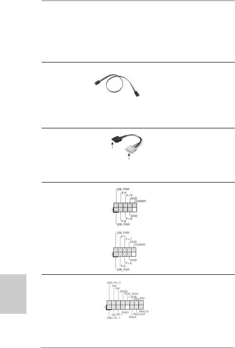
eSATAII Connector
(eSATAII_TOP: see p.2, No. 38)  TOP_eSATAII
Serial ATA (SATA) Data Cable
(Optional)
Serial ATA (SATA)
Power Cable
(Optional)
connect to the SATA
HDD power connector
connect to the power supply
USB 2.0 Headers
(9-pin USB8_9)
(see p.2 No. 19)
(9-pin USB6_7)
(see p.2 No. 17)
This eSATAII connector supports SATA data cable for external SATAII function. The current eSATAII interface allows up to 3.0 Gb/s data transfer rate.
Either end of the SATA data cable can be connected to the SATA / SATAII hard disk or the SATAII connector on this motherboard. You can also use the SATA data cable to connect SATAII_6
(PORT5) connector and eSATAII connector.
Please connect the black end of SATA power cable to the power connector on each drive. Then connect the white end of SATA power cable to the power connector of the power supply.
Besides six default USB 2.0 ports on the I/O panel, there are two USB 2.0 headers on this motherboard. Each USB 2.0 header can support two USB 2.0 ports.
hsilgnE
WiFi/E Header
(15-pin WIFI/E)
(see p.2 No. 37)
2 6
This header supports WiFi+AP function with ASRock WiFi-802.11g or WiFi-802.11n module, an easy-to-use wireless local area network (WLAN) adapter. It allows you to create a wirelessenvironmentandenjoythe convenience of wireless network connectivity.
ASRock K10N780SLIX3-WiFi Motherboard
If you don’t plan to use WiFi+AP functin on this motherboard, this header can be used as a 4-Pin USB 2.0 header to support one USB 2.0 port. To connect the 4-Pin USB device cable to this header, please refer to
this picture for proper installation.
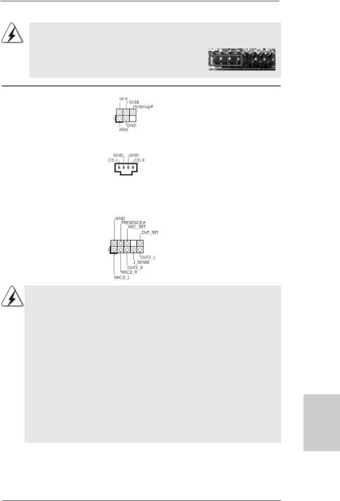
DeskExpress Hot Plug Detection |
This header supports the Hot |
Header |
Plug detection function for |
(5-pin IR1) |
ASRock DeskExpress. |
(see p.2 No. 27) |
|
|
|
Internal Audio Connectors |
This connector allows you |
(4-pin CD1) |
to receive stereo audio input |
(CD1: see p.2, No. 31) |
from sound sources such as |
CD1 |
a CD-ROM, DVD-ROM, TV |
|
tuner card, or MPEG card. |
|
|
Front Panel Audio Header |
This is an interface for the front |
(9-pin HD_AUDIO1) |
panel audio cable that allows |
(see p.2, No. 30) |
convenient connection and |
|
control of audio devices. |
1.High Definition Audio supports Jack Sensing, but the panel wire on the chassis must support HDA to function correctly. Please follow the instruction in our manual and chassis manual to install your system.
2.If you use AC’97 audio panel, please install it to the front panel audio header as below:
A.Connect Mic_IN (MIC) to MIC2_L.
B.Connect Audio_R (RIN) to OUT2_R and Audio_L (LIN) to OUT2_L.
C.Connect Ground (GND) to Ground (GND).
D.MIC_RET and OUT_RET are for HD audio panel only. You don’t need to connect them for AC’97 audio panel.
E.Enter BIOS Setup Utility. Enter Advanced Settings, and then select Chipset Configuration. Set the Front Panel Control option from
[Auto] to [Enabled].
F.Enter Windows system. Click the icon on the lower right hand taskbar to enter Realtek HD Audio Manager.
English
2 7
ASRock K10N780SLIX3-WiFi Motherboard
For Windows® XP / XP 64-bit OS:
Click “Audio I/O”, select “Connector Settings”  , choose
“Disable front panel jack detection”, and save the change by clicking “OK”.
For Windows® VistaTM / VistaTM 64-bit OS:
Click the right-top “Folder” icon |
, choose “Disable front |
panel jack detection”, and save the change by clicking “OK”. |
|
|
|
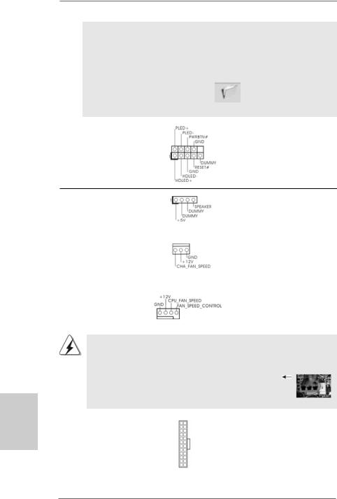
System Panel Header |
This header accommodates |
(9-pin PANEL1) |
several system front panel |
(see p.2, No. 22) |
functions. |
hsilgnE
Chassis Speaker Header |
|
Please connect the chassis |
(4-pin SPEAKER 1) |
|
speaker to this header. |
(see p.2, No. 25) |
|
|
|
|
|
Chassis Fan Connector |
|
Please connect a chassis fan |
(3-pin CHA_FAN1) |
|
cable to this connector and |
(see p.2, No. 21) |
|
match the black wire to the |
|
|
ground pin. |
|
|
|
CPU Fan Connector |
|
Please connect the CPU fan |
(4-pin CPU_FAN1) |
|
cable to this connector and |
(see p.2, No. 5) |
|
match the black wire to the |
|
1 2 3 4 |
ground pin. |
|
|
Though this motherboard provides 4-Pin CPU fan (Quiet Fan) support, the 3-Pin CPU fan still can work successfully even without the fan speed control function. If you plan to connect the 3-Pin CPU fan to the CPU fan connector on this motherboard, please connect it to Pin 1-3.
|
|
|
Pin 1-3 Connected |
|
|
|
3-Pin Fan Installation |
|
|
|
|
ATX Power Connector |
12 |
24 |
Please connect an ATX power |
(24-pin ATXPWR1) |
|
|
supply to this connector. |
(see p.2, No. 8) |
|
|
|
|
1 |
13 |
|
2 8
ASRock K10N780SLIX3-WiFi Motherboard
|
Though this motherboard provides 24-pin ATX power connector, 12 |
24 |
|
it can still work if you adopt a traditional 20-pin ATX power supply. |
|
|
To use the 20-pin ATX power supply, please plug your power |
|
|
supply along with Pin 1 and Pin 13. |
|
|
20-Pin ATX Power Supply Installation |
13 |
|
1 |
|
|
|
|
|
|
|
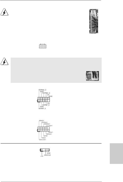
ATX 12V Power Connector
(8-pin ATX12V1) |
8 |
5 |
|
||
(see p.2, No. 2) |
4 |
1 |
|
Please note that it is necessary to connect a power supply with ATX 12V plug to this connector. Failing to do so will cause power up failure.
Though this motherboard provides 8-pin ATX 12V power connector, it can still work if you adopt a traditional 4-pin ATX 12V power supply. To use the 4-pin ATX power supply, please plug your power supply along with Pin 1 and Pin 5.
|
|
8 |
5 |
|
4-Pin ATX 12V Power Supply Installation |
4 |
1 |
|
|
||
|
|
|
|
IEEE 1394 Header |
Besides one default IEEE 1394 |
|
|
(9-pin FRONT_1394) |
port on the I/O panel, there is one |
||
(see p.2 No. 26) |
IEEE 1394 header |
|
|
|
(FRONT_1394) on this |
|
|
|
motherboard. This IEEE 1394 |
|
|
|
header can support one IEEE |
|
|
|
1394 port. |
|
|
|
|
|
|
Serial port Header |
This COM1 header |
|
|
(9-pin COM1) |
supports a serial port module. |
|
|
(see p.2 No.24) |
|
|
|
on
HDMI_SPDIF Header |
HDMI_SPDIF header, providing |
(3-pin HDMI_SPDIF1) |
SPDIF audio output to HDMI VGA |
(see p.2, No. 29) |
card, allows the system to |
|
con nect HDMI Digital TV/ |
|
projector/LCD devices. Please |
|
connect the HDMI_SPDIF |
|
connector of HDMI VGA card to |
|
this header. |
2 9
English
ASRock K10N780SLIX3-WiFi Motherboard
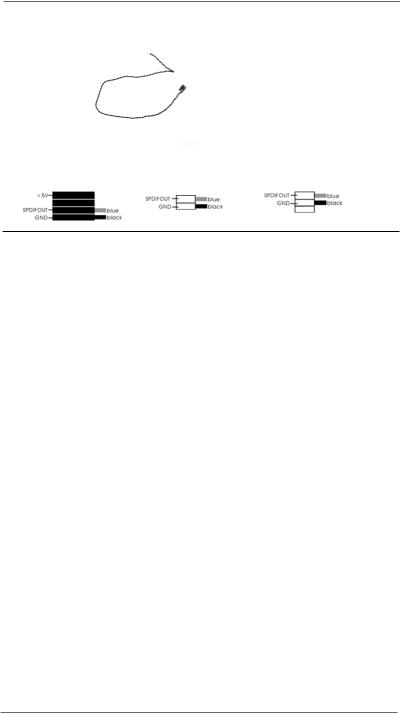
HDMI_SPDIF Cable
(Optional)
A. black end
|
Please connect the black end (A) |
C |
of HDMI_SPDIF cable to the |
B |
HDMI_SPDIF header on the |
Amotherboard. Then connect the white end (B or C) of HDMI_SPDIF cable to the HDMI_SPDIF connector of HDMI VGA card.
B. white end (2-pin) |
C. white end (3-pin) |
2.9 HDMI_SPDIF Header Connection Guide
HDMI (High-Definition Multi-media Interface) is an all-digital audio/video specification, which provides an interface between any compatible digital audio/video source, such as a set-top box, DVD player, A/V receiver and a compatible digital audio or video monitor, such as a digital television (DTV). This motherboard is equipped with a HDMI_SPDIF header, which provides SPDIF audio output to HDMI VGA card, allows the system to connect HDMI Digital TV/projector/LCD devices. To use HDMI function on this motherboard, please refer to page 36 of “User Manual” in the support CD for detailed installation procedures.
2.10 eSATAII Interface Introduction
|
|
NOTE: |
||
|
|
1. |
If you set “SATA Operation Mode” option in BIOS setup to AHCI or RAID mode, Hot |
|
|
|
|
Plug function is supported with eSATAII devices. Therefore, you can insert or remove |
|
|
|
|
your eSATAII devices to the eSATAII ports while the system is power-on and in |
|
|
|
|
working condition. |
|
|
|
2. |
If you set “SATA Operation Mode” option in BIOS setup to non-RAID mode, Hot Plug |
|
|
|
|
function is not supported with eSATAII devices. If you still want to use eSATAII |
|
|
|
|
function in non-RAID mode, please insert or remove your eSATAII devices to the |
|
|
|
|
eSATAII ports only when the system is power-off. |
|
|
|
3. |
If you want to use the eSATAII HDD as an OS disk, please set “SATA Operation |
|
nE |
||||
|
|
Mode” option in BIOS setup to non-RAID mode. If you want to use the eSATAII HDD |
||
lg |
|
|
as a removable data disk, please set “SATA Operation Mode” option in BIOS setup |
|
si |
|
|
to RAID mode. If you want to add the eSATAII HDD as a RAID disk, please set “SATA |
|
h |
|
|
||
|
|
Operation Mode” option in BIOS setup to RAID mode. |
||
|
|
|
||
|
|
4. |
Please do not configure your eSATAII HDD as a RAID disk; otherwise, it may affect |
|
|
|
|
the Hot Plug function that eSATAII HDD should have. |
|
|
|
5. |
Please refer to page 32 to 34 for detailed information of RAID mode, non-RAID |
|
|
|
|
mode and AHCI mode. |
|
|
|
|
|
|
3 0
ASRock K10N780SLIX3-WiFi Motherboard
 Loading...