


Version 1.0
Published April 2013
Copyright©2013 ASRock INC. All rights reserved.
Copyright Notice:
No part of this documentation may be reproduced, transcribed, transmitted, or translated in any language, in any form or by any means, except duplication of documentation by the purchaser for backup purpose, without written consent of ASRock Inc.
Products and corporate names appearing in this documentation may or may not be registered trademarks or copyrights of their respective companies, and are used only for identification or explanation and to the owners’ benefit, without intent to
infringe.
Disclaimer:
Specifications and information contained in this documentation are furnished for informational use only and subject to change without notice, and should not be constructed as a commitment by ASRock. ASRock assumes no responsibility for any errors or omissions that may appear in this documentation.
With respect to the contents of this documentation, ASRock does not provide warranty of any kind, either expressed or implied, including but not limited to the implied warranties or conditions of merchantability or fitness for a particular purpose.
In no event shall ASRock, its directors, officers, employees, or agents be liable for any indirect, special, incidental, or consequential damages (including damages for loss of profits, loss of business, loss of data, interruption of business and the like), even if ASRock has been advised of the possibility of such damages arising from any defect or error in the documentation or product.
The terms HDMI™ and HDMI High-Definition Multimedia Interface, and the HDMI logo are trademarks or registered trademarks of HDMI Licensing LLC in the United States and other countries.
This device complies with Part 15 of the FCC Rules. Operation is subject to the following two conditions:
(1)this device may not cause harmful interference, and
(2)this device must accept any interference received, including interference that may cause undesired operation.
CALIFORNIA, USA ONLY
The Lithium battery adopted on this motherboard contains Perchlorate, a toxic substance controlled in Perchlorate Best Management Practices (BMP) regulations passed by the California Legislature. When you discard the Lithium battery in California, USA, please follow the related regulations in advance.
“Perchlorate Material-special handling may apply, see www.dtsc.ca.gov/hazardouswaste/ perchlorate”
ASRock Website: http://www.asrock.com

|
|
|
|
|
|
|
|
|
|
|
H87M-ITX |
|
||||
Motherboard Layout |
|
|
|
|
|
|
|
|
|
|
|
|||||
|
|
|
|
1 |
|
|
|
|
|
|
2 |
|
|
|
|
|
/Mouse Keyboard PS2 |
USB 2.0 |
|
|
|
|
|
|
|
|
|
|
|
|
|
|
|
|
T: USB2 |
|
|
|
|
|
|
|
|
|
|
|
|
|
|
|
|
B: USB3 |
|
|
|
|
|
|
|
|
|
|
|
|
|
|
|
|
|
|
|
ATX12V1 |
|
|
|
|
|
|
|
|
|
|
|
|
VGA1 |
DVI |
|
|
|
|
|
|
|
|
|
|
|
CLRCMOS1 |
1 |
|
3 |
|
|
|
|
|
|
|
|
|
|
|
|
|
CI1 |
|
|
4 |
|
|
|
|
|
|
|
|
|
|
module)pin-240bit,(64A1 |
module)pin-240bit,(64B1 |
ATXPWR1 |
1 |
|
|
|
HDMI1 |
|
A1ATeS |
|
XFast RAM |
|
|
|
|
|
|
|
|||||
|
|
|
|
|
|
|
|
|
|
|
|
|
|
|||
|
|
|
|
|
|
|
|
|
|
|
|
|
|
|
|
5 |
USB 3.0 |
|
|
RoHS |
|
|
|
|
|
|
|
|
|
|
|
|
|
|
|
|
|
|
|
|
|
|
|
|
|
|
|
|
||
T: USB1 |
|
|
|
|
|
|
|
|
|
|
|
|
|
|
|
|
B: USB2 |
|
|
|
|
|
USB 3.0 |
|
|
|
|
|
|
|
|||
|
|
|
|
|
|
|
|
|
|
|
|
|
|
|||
|
|
|
|
|
|
|
FAN1CPU |
|
|
_ |
_ |
|
|
|
|
6 |
|
|
|
Top: |
|
|
|
|
Battery |
DDR3 |
DDR3 |
|
|
|
|
7 |
|
USB 3.0 |
|
|
|
|
|
|
|
CMOS |
|
|
|
|
|
|
|
|
T: USB3 |
|
RJ-45 |
|
Intel |
|
|
|
|
|
|
|
|
|
|
|
|
B: USB4 |
TPMS1 |
|
FAN1 CHA |
|
|
|
|
|
|
|
|
|
||||
|
|
|
|
H87 |
|
|
|
|
|
|
|
|
|
|
||
SPDIF Optical Bottom: |
REARSPK Center: |
CTBASSR op:T |
AUDIO1HD |
|
|
|
|
|
|
|
|
|
|
|
|
|
1 |
64Mb |
33 |
23 |
13 |
03 |
|
|
|
USB3_5_6 |
|
||||||
|
|
|
|
|
|
|
|
|
|
|
|
|
|
|
|
8 |
MI Bottom: CN |
FRONT Center: |
LINE Top: |
|
1 CODEC |
BIOS |
SATA_ |
SATA_ |
SATA_ |
SATA_ |
|
|
|
PLEDPWRBTN |
|
HDLEDRESET |
|
|
H87M-ITX |
|
|
|
1 |
9 |
||||||||||
|
|
|
|
AUDIO |
|
|
|
|
|
|
1 |
|
|
|
|
|
|
|
|
|
|
PCIE1 |
|
|
|
|
|
USB_10_11 |
|
PANEL1 |
|
|
|
|
|
|
|
|
|
|
|
|
Super |
|
|
|
|
|
|
|
|
|
|
|
|
|
|
|
|
|
I/O |
|
|
|
|
|
|
|
|
|
16 |
15 |
14 |
13 |
12 |
11 |
10 |
|
|
|
|
|
|
|
English
1

No. Description
1ATX 12V Power Connector (ATX12V1)
22 x 240-pin DDR3 DIMM Slots (DDR3_A1, DDR3_B1)
3Clear CMOS Jumper (CLRCMOS1)
4Chassis Intrusion Header (CI1)
5ATX Power Connector (ATXPWR1)
6CPU Fan Connector (CPU_FAN1)
7USB 3.0 Header (USB3_5_6)
8USB 2.0 Header (USB10_11)
9System Panel Header (PANEL1)
10SATA3 Connector (SATA3_0)
11SATA3 Connector (SATA3_1)
12SATA3 Connector (SATA3_2)
13SATA3 Connector (SATA3_3)
14Chassis Fan Connector (CHA_FAN1)
15TPM Header (TPMS1)
16Front Panel Audio Header (HD_AUDIO1)
English
2

H87M-ITX
I/O Panel
|
|
|
|
|
|
|
|
|
|
|
|
|
|
|
|
|
|
|
|
|
5 |
7 |
|
1 |
|
|
2 |
|
|
3 |
|
4 |
|
|
|
|
|
6 |
8 |
||||||
|
|
|
|
|
|
|
|
|
|
|
|
|
|
|
|
|
|
|
|
|
|
|
|
|
|
|
|
|
|
|
|
|
|
|
|
|
|
|
|
|
|
|
|
|
|
|
|
|
|
|
|
|
|
|
|
|
|
|
|
|
|
|
|
|
|
|
|
|
|
|
|
|
|
|
|
|
|
|
|
|
|
|
|
|
|
|
|
|
|
|
|
|
|
|
|
|
|
|
|
|
|
|
|
|
|
|
|
|
|
|
|
|
|
|
|
|
|
|
|
|
|
|
|
|
|
|
|
|
|
|
|
|
|
|
|
|
|
|
|
|
|
|
|
|
|
|
|
|
|
|
|
|
|
|
|
|
|
|
|
|
|
|
|
|
|
|
|
|
|
|
|
|
|
|
|
|
|
|
|
|
|
|
|
|
|
|
|
|
|
|
|
|
|
|
|
|
|
|
|
|
|
|
|
|
|
|
|
|
|
|
|
|
|
|
|
|
|
|
|
|
|
|
|
|
|
|
|
|
|
|
|
|
|
|
|
|
|
|
|
|
|
|
|
|
|
|
|
|
|
|
|
|
|
|
|
|
|
|
|
|
|
|
|
|
15 |
14 |
|
|
13 |
|
|
12 |
|
|
|
11 |
|
|
10 |
9 |
||
No. |
|
Description |
|
|
|
|
|
No. |
Description |
|
|
|
|
|
||||
|
|
|
|
|
|
|
|
|
|
|
||||||||
1 |
|
USB 2.0 Ports (USB_23) |
|
9 |
Microphone (Pink) |
|
|
|||||||||||
2 |
|
VGA Port |
|
|
|
|
10 |
Optical SPDIF Out Port |
|
|
||||||||
3 |
|
eSATA Connector*** |
|
11 |
USB 3.0 Ports (USB_01) |
|
|
|||||||||||
4 |
|
LAN RJ-45 Port* |
|
12 |
USB 3.0 Ports (USB3_12) |
|
|
|||||||||||
5 |
|
Central / Bass (Orange) |
|
13 |
HDMI Port |
|
|
|
|
|
||||||||
6 |
|
Rear Speaker (Black) |
|
14 |
DVI-D Port |
|
|
|
|
|
||||||||
7 |
|
Line In (Light Blue) |
|
15 |
PS/2 Keyboard/Mouse Port |
|
||||||||||||
8 |
|
Front Speaker (Lime)** |
|
|
|
|
|
|
|
|
|
|
|
|
|
|||
|
|
|
|
|
|
|
|
|
|
|
|
|
|
|
|
|
|
|
English
3
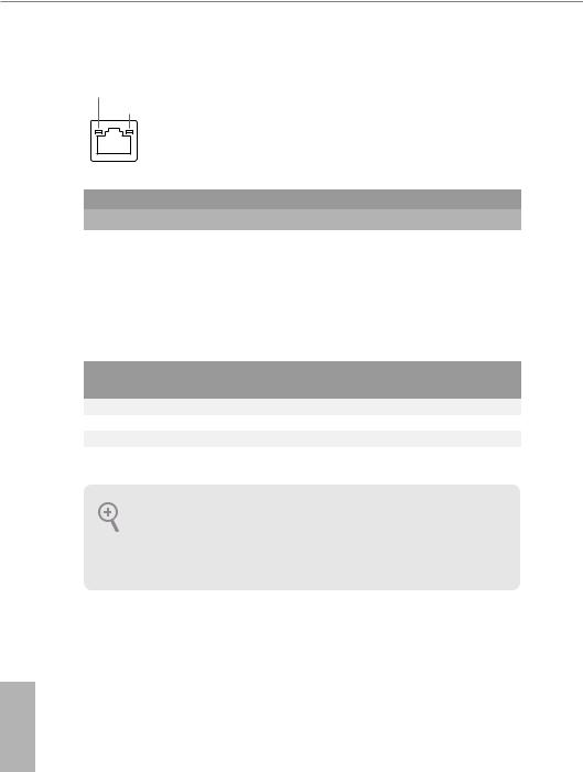
*There are two LEDs on each LAN port. Please refer to the table below for the LAN port LED indications.
ACT/LINK LED SPEED LED
LAN Port |
|
|
|
|
|
|
Activity / Link LED |
|
Speed LED |
|
|
||
|
|
|
||||
Status |
|
Description |
|
Status |
|
Description |
Off |
|
No Link |
|
Off |
|
10Mbps connection |
|
|
|
||||
Blinking |
|
Data Activity |
|
Orange |
|
100Mbps connection |
On |
|
Link |
|
Green |
|
1Gbps connection |
|
|
|
|
|
|
|
** If you use a 2-channel speaker, please connect the speaker’s plug into “Front Speaker Jack”. See the table below for connection details in accordance with the type of speaker you use.
Audio Output |
Front Speaker |
Rear Speaker |
Central / Bass |
Line In |
Channels |
(No. 8) |
(No. 6) |
(No. 5) |
(No. 7) |
2 |
V |
-- |
-- |
-- |
4 |
V |
V |
-- |
-- |
6 |
V |
V |
V |
-- |
8 |
V |
V |
V |
V |
To enable Multi-Streaming, you need to connect a front panel audio cable to the front panel audio header. After restarting your computer, you will find the “Mixer” tool on your system. Please select “Mixer ToolBox”  , click “Enable playback multi-streaming”, and click “ok”. Choose “2CH”, “4CH”, “6CH”, or “8CH” and then you are allowed to select “Realtek HDA Primary output” to use the Rear Speaker, Central/Bass, and Front Speaker, or select “Realtek HDA Audio 2nd output” to use the front panel audio.
*** The eSATA connector supports SATA with cables within 1 meters.
English
4

H87M-ITX
Chapter 1 Introduction
Thank you for purchasing ASRock H87M-ITX motherboard, a reliable motherboard produced under ASRock’s consistently stringent quality control. It delivers excellent performance with robust design conforming to ASRock’s commitment to quality and endurance.
Because the motherboard specifications and the BIOS software might be updated, the content of this documentation will be subject to change without notice. In case any modifications of this documentation occur, the updated version will be available on ASRock’s website without further notice. If you require technical support related to this motherboard, please visit our website for specific information about the model you are using. You may find the latest VGA cards and CPU support list on ASRock’s website as well. ASRock website http://www.asrock.com.
1.1 Package Contents
•ASRock H87M-ITX Motherboard (Mini-ITX Form Factor)
•ASRock H87M-ITX Quick Installation Guide
•ASRock H87M-ITX Support CD
•2 x Serial ATA (SATA) Data Cables (Optional)
•1 x I/O Panel Shield
English
5

English
1.2 Specifications
Platform |
• |
Mini-ITX Form Factor |
|
• All Solid Capacitor design |
|
A-Style |
• |
Home Cloud |
CPU |
• |
Supports 4th Generation Intel® CoreTM i7 / i5 / i3 / Xeon® / |
|
|
Pentium® / Celeron® in LGA1150 Package |
|
• 4 Power Phase Design |
|
|
• Supports Intel® Turbo Boost 2.0 Technology |
|
Chipset |
• |
Intel® H87 |
|
• Supports Intel® Small Business Advantage 2.0 |
|
Memory |
• |
Dual Channel DDR3 Memory Technology |
|
• 2 x DDR3 DIMM slots |
|
|
• Supports DDR3 1600/1333/1066 non-ECC, un-buffered |
|
|
|
memory |
|
• Max. capacity of system memory: 16GB |
|
|
|
(see CAUTION) |
|
• Supports Intel® Extreme Memory Profile (XMP)1.3/1.2 |
|
Expansion |
• |
1 x PCI Express 3.0 x16 slot |
Slot |
|
|
Graphics |
• |
Intel® HD Graphics Built-in Visuals and the VGA outputs can |
|
|
be supported only with processors which are GPU integrated. |
|
• Supports Intel® HD Graphics Built-in Visuals : Intel® Quick |
|
|
|
Sync Video with AVC, MVC (S3D) and MPEG-2 Full |
|
|
HW Encode1, Intel® InTruTM 3D, Intel® Clear Video HD |
|
|
Technology, Intel® InsiderTM, Intel® HD Graphics 4400/4600 |
|
• Pixel Shader 5.0, DirectX 11.1 |
|
|
• Max. shared memory 1792MB |
|
|
• Three VGA Output options: D-Sub, DVI-D and HDMI |
|
|
• |
Supports Triple Monitors |
|
• Supports HDMI Technology with max. resolution up to |
|
1920x1200 @ 60Hz
• Supports DVI-D with max. resolution up to 1920x1200 @ 60Hz
6

H87M-ITX
• Supports D-Sub with max. resolution up to 1920x1200 @ 60Hz
• Supports Auto Lip Sync, Deep Color (12bpc), xvYCC and
|
|
HBR (High Bit Rate Audio) with HDMI (Compliant HDMI |
|
|
monitor is required) |
|
• Supports HDCP function with DVI-D and HDMI ports |
|
|
• Supports Full HD 1080p Blu-ray (BD) playback with DVI-D |
|
|
|
and HDMI ports |
Audio |
• |
7.1 CH HD Audio with Content Protection (Realtek ALC892 |
|
|
Audio Codec) |
|
• Premium Blu-ray audio support |
|
LAN |
• |
PCIE x1 Gigabit LAN 10/100/1000 Mb/s |
|
• |
Qualcomm® Atheros® AR8171 |
|
• Supports Qualcomm® Atheros® Security Wake On Internet |
|
|
|
Technology |
|
• Supports Wake-On-LAN |
|
|
• Supports Energy Efficient Ethernet 802.3az |
|
|
• |
Supports PXE |
Rear Panel |
• |
1 x PS/2 Mouse/Keyboard Port |
I/O |
• |
1 x D-Sub Port |
• 1 x DVI-D Port
• 1 x HDMI Port
• 1 x Optical SPDIF Out Port
• 1 x eSATA Connector
• 2 x USB 2.0 Ports
• 4 x USB 3.0 Ports
• 1 x RJ-45 LAN Port with LED (ACT/LINK LED and SPEED LED)
• HD Audio Jack: Rear Speaker / Central / Bass / Line in / Front Speaker / Microphone
English
7

English
Storage |
• |
4 x SATA3 6.0 Gb/s connectors, support RAID (RAID 0, |
|
|
RAID 1, RAID 5, RAID 10, Intel Rapid Storage Technology |
|
|
12 and Intel Smart Response Technology), NCQ, AHCI and |
|
|
“Hot Plug” functions |
|
• 1 x eSATA connector, supports NCQ, AHCI and “Hot Plug” |
|
|
|
functions |
Connector |
• |
1 x Chassis Intrusion header |
|
• 1 x TPM header |
|
|
• 1 x CPU Fan connector (4-pin) |
|
|
• 1 x Chassis Fan connector (4-pin) |
|
|
• 1 x 24 pin ATX power connector |
|
|
• 1 x 4 pin 12V power connector |
|
|
• 1 x Front panel audio connector |
|
|
• 1 x USB 2.0 header (supports 2 USB 2.0 ports) |
|
|
• 1 x USB 3.0 header (supports 2 USB 3.0 ports) |
|
BIOS |
• |
64Mb AMI UEFI Legal BIOS with Multilingual GUI support |
Feature |
• |
ACPI 1.1 Compliance Wake Up Events |
|
• |
SMBIOS 2.3.1 Support |
|
• CPU, DRAM, PCH 1.05V, PCH 1.5V Voltage Multi-adjust- |
|
|
|
ment |
Support |
• |
Drivers, Utilities, AntiVirus Software (Trial Version), Cyber- |
CD |
|
Link MediaEspresso 6.5 Trial, Google Chrome Browser and |
|
|
Toolbar, Start8 (30 days trial) |
Hardware |
• |
CPU/Chassis Temperature Sensing |
Monitor |
• |
CPU/Chassis Tachometer |
|
• CPU/Chassis Quiet Fan (Allow Chassis Fan Speed Auto- |
|
|
|
Adjust by CPU Temperature) |
|
• CPU/Chassis Fan Multi-Speed Control |
|
|
• |
CASE OPEN detection |
|
• Voltage Monitoring: +12V, +5V, +3.3V, CPU Vcore |
|
OS |
• |
Microsoft® Windows® 8 / 8 64-bit / 7 / 7 64-bit compliant |
Certifica- |
• |
FCC, CE, WHQL |
tions |
• |
ErP/EuP Ready (ErP/EuP ready power supply is required) |
8

H87M-ITX
* For detailed product information, please visit our website: http://www.asrock.com
Due to limitation, the actual memory size may be less than 4GB for the reservation for system usage under Windows® 32-bit operating systems. Windows® 64-bit operating systems do not have such limitations. You can use ASRock XFast RAM to utilize the memory that Windows® cannot use.
English
9
1.3 Unique Features
ASRock A-Tuning
A-Tuning is ASRock’s multi purpose software suite with a new interface, more new features and improved utilities, including XFast RAM, Dehumidifier, Good Night LED, FAN-Tastic Tuning, OC Tweaker and a whole lot more.
 ASRock Instant Flash
ASRock Instant Flash is a BIOS flash utility embedded in Flash ROM. This convenient BIOS update tool allows you to update the system BIOS in a few clicks without preparing an additional floppy diskette or other complicated flash utility. Just save the new BIOS file to your USB storage and launch this tool by pressing <F6> or <F2> during POST to enter the BIOS setup menu to access ASRock Instant Flash. Please be noted that the USB flash drive or hard drive must use FAT32/16/12 file system.
ASRock APP Charger
Simply by installing the ASRock APP Charger makes your iPhone/iPad/iPod Touch charge up to 40% faster than before on your computer. ASRock APP Charger allows you to quickly charge many Apple devices simultaneously and even supports continuous charging when your PC enters into Standby mode (S1), Suspend to RAM (S3), hibernation mode (S4) or power off (S5).
ASRock XFast USB
ASRock XFast USB can boost the performance of your USB storage devices. The performance may depend on the properties of the device.
ASRock XFast LAN
ASRock XFast LAN provides faster internet access, which includes the benefits listed below. LAN Application Prioritization: You can configure your application’s priority ideally and add new programs to the list. Lower Latency in Game: After setting online game’s priority higher, it can lower the latency in games. Traffic Shaping: You can watch Youtube HD videos and download simultaneously. RealTime Analysis of Your Data: With the status window, you can easily recognize which data streams you are currently transferring.
English
10

H87M-ITX
ASRock XFast RAM
ASRock XFast RAM is included in A-Tuning. It fully utilizes the memory space that cannot be used under Windows® 32-bit operating systems. ASRock XFast RAM shortens the loading time of previously visited websites, making web surfing faster than ever. And it also boosts the speed of Adobe Photoshop 5 times faster. Another advantage of ASRock XFast RAM is that it reduces the frequency of accessing your SSDs or HDDs in order to extend their lifespan.
ASRock Crashless BIOS
ASRock Crashless BIOS allows users to update their BIOS without fear of failing. If power loss occurs during the BIOS updating process, ASRock Crashless BIOS will automatically finish the BIOS update procedure after regaining power. Please note that BIOS files need to be placed in the root directory of your USB disk. Only USB 2.0 ports support this feature.
ASRock OMG (Online Management Guard)
Administrators are able to establish an internet curfew or restrict internet access at specified times via OMG. You may schedule the starting and ending hours of internet access granted to other users. In order to prevent users from bypassing OMG, guest accounts without permission to modify the system time are required.

 ASRock Internet Flash
ASRock Internet Flash downloads and updates the latest UEFI firmware version from our servers for you without entering Windows® OS. Please setup network configuration before using Internet Flash.


 ASRock UEFI System Browser
ASRock System Browser shows the overview of your current PC and the devices connected.
ASRock Dehumidifier Function
Users may prevent motherboard damages due to dampness by enabling “Dehumidifier Function”. When enabling Dehumidifier Function, the computer will power on automatically to dehumidify the system after entering S4/S5 state.
ASRock Easy RAID Installer
ASRock Easy RAID Installer can help you to copy the RAID driver from the support CD to your USB storage device. After copying the RAID driver to your USB storage device, please change “SATA Mode” to “RAID”, then you can start installing the OS in RAID mode.
English
11

English
 ASRock Easy Driver Installer
For users that don’t have an optical disk drive to install the drivers from our support CD, Easy Driver Installer is a handy tool in the UEFI that installs the LAN driver to your system via an USB storage device, then downloads and installs the other required drivers automatically.


 ASRock Interactive UEFI
ASRock Interactive UEFI is a blend of system configuration tools, cool sound effects and stunning visuals. The unprecedented UEFI provides a more attractive interface and more amusment.
 ASRock Fast Boot
With ASRock’s exclusive Fast Boot technology, it takes less than 1.5 seconds to logon to Windows 8 from a cold boot. No more waiting! The speedy boot will completely change your user experience and behavior.
ASRock Restart to UEFI
Windows® 8 brings the ultimate boot up experience. The lightning boot up speed makes it hard to access the UEFI setup. ASRock Restart to UEFI allows users to enter the UEFI automatically when turning on the PC. By enabling this function, the PC will enter the UEFI directly after you restart.
ASRock Good Night LED
ASRock Good Night LED technology offers you a better sleeping environment by extinguishing the unessential LEDs. By enabling Good Night LED in the BIOS, the Power/HDD LEDs will be switched off when the system is powered on. Good Night LED will automatically switch off the Power and Keyboard LEDs when the system enters into Standby/Hibernation mode as well.
 ASRock USB Key
In a world where time is money, why waste precious time everyday typing usernames to log in to Windows? Why should we even bother memorizing those foot long passwords? Just plug in the USB Key and let your computer log in to windows automatically!
 ASRock Home Cloud
This motherboard supports Security Wake On Internet Technology with the onboard Qualcomm® Atheros® LAN, so you can connect with your PC from anywhere in the world. You will be able to power your PC on or turn it off, monitor and take control of it remotely with another smartphone, tablet or computer.
12

H87M-ITX
 ASRock FAN-Tastic Tuning
ASRock FAN-Tastic Tuning is included in A-Tuning. Configure up to five different fan speeds using the graph. The fans will automatically shift to the next speed level when the assigned temperature is met.
English
13

Chapter 2 Installation
This is an Mini-ITX form factor motherboard. Before you install the motherboard, study the configuration of your chassis to ensure that the motherboard fits into it.
Pre-installation Precautions
Take note of the following precautions before you install motherboard components or change any motherboard settings.
•Make sure to unplug the power cord before installing or removing the motherboard. Failure to do so may cause physical injuries to you and damages to motherboard components.
•In order to avoid damage from static electricity to the motherboard’s components, NEVER place your motherboard directly on a carpet. Also remember to use a grounded wrist strap or touch a safety grounded object before you handle the components.
•Hold components by the edges and do not touch the ICs.
•Whenever you uninstall any components, place them on a grounded anti-static pad or in the bag that comes with the components.
•When placing screws to secure the motherboard to the chassis, please do not overtighten the screws! Doing so may damage the motherboard.
14

H87M-ITX
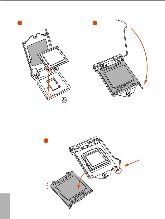
2.1Installing the CPU
1.Before you insert the 1150-Pin CPU into the socket, please check if the PnP cap is on the socket, if the CPU surface is unclean, or if there are any bent pins in the socket. Do not force to insert the CPU into the socket if above situation is found. Otherwise, the CPU will be seriously damaged.
2.Unplug all power cables before installing the CPU.
1
A
 B
B
2
English
15
3 |
4 |
5
English
16

H87M-ITX
Please save and replace the cover if the processor is removed. The cover must be placed if you wish to return the motherboard for after service.
English
17

2.2 Installing the CPU Fan and Heatsink
1 |
2 |
N _FA PU C
English
18

H87M-ITX
2.3 Installing Memory Modules (DIMM)
This motherboard provides two 240-pin DDR3 (Double Data Rate 3) DIMM slots, and supports Dual Channel Memory Technology.
1.For dual channel configuration, you always need to install identical (the same brand, speed, size and chip-type) DDR3 DIMM pairs.
2.It is unable to activate Dual Channel Memory Technology with only one memory module installed.
3.It is not allowed to install a DDR or DDR2 memory module into a DDR3 slot; otherwise, this motherboard and DIMM may be damaged.
The DIMM only fits in one correct orientation. It will cause permanent damage to the motherboard and the DIMM if you force the DIMM into the slot at incorrect orientation.
English
19
1
2
3
English
20
H87M-ITX
2.4 Expansion Slots (PCI and PCI Express Slots)
There is 1 PCI Express slot on this motherboard.
Before installing an expansion card, please make sure that the power supply is switched off or the power cord is unplugged. Please read the documentation of the expansion card and make necessary hardware settings for the card before you start the installation.
PCIe slots:
PCIE1 (PCIe 3.0 x16 slot) is used for PCI Express x16 lane width graphics cards.
English
21
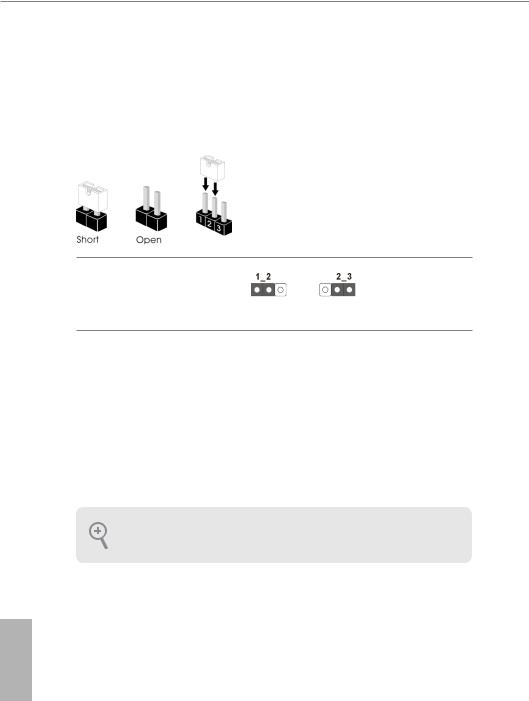
2.5 Jumpers Setup
The illustration shows how jumpers are setup. When the jumper cap is placed on the pins, the jumper is “Short”. If no jumper cap is placed on the pins, the jumper is “Open”. The illustration shows a 3-pin jumper whose pin1 and pin2 are “Short” when a jumper cap is placed on these 2 pins.
Clear CMOS Jumper |
|
|
|
(CLRCMOS1) |
Default |
Clear CMOS |
|
(see p.1, No. 3) |
|||
|
|
CLRCMOS1 allows you to clear the data in CMOS. To clear and reset the system parameters to default setup, please turn off the computer and unplug the power cord from the power supply. After waiting for 15 seconds, use a jumper cap to short pin2 and pin3 on CLRCMOS1 for 5 seconds. However, please do not clear the CMOS right after you update the BIOS. If you need to clear the CMOS when you just finish updating the BIOS, you must boot up the system first, and then shut it down before you do the clear-CMOS action. Please be noted that the password, date, time, and user default profile will be cleared only if the CMOS battery is removed.
If you clear the CMOS, the case open may be detected. Please adjust the BIOS option “Clear
Status” to clear the record of previous chassis intrusion status.
English
22

H87M-ITX
2.6 Onboard Headers and Connectors
Onboard headers and connectors are NOT jumpers. Do NOT place jumper caps over these headers and connectors. Placing jumper caps over the headers and connectors will cause permanent damage to the motherboard.
System Panel Header
(9-pin PANEL1)
(see p.1, No. 9)
|
GND |
GND |
RESET# |
PWRBTN# |
GND |
PLED- |
HDLED- |
PLED+ |
HDLED+ |
|
1 |
Connect the power switch, reset switch and system status indicator on the chassis to this header according to the pin assignments below. Note the positive and negative pins before connecting the cables.
PWRBTN (Power Switch):
Connect to the power switch on the chassis front panel. You may configure the way to turn off your system using the power switch.
RESET (Reset Switch):
Connect to the reset switch on the chassis front panel. Press the reset switch to restart the computer if the computer freezes and fails to perform a normal restart.
PLED (System Power LED):
Connect to the power status indicator on the chassis front panel. The LED is on when the system is operating. The LED keeps blinking when the system is in S1/S3 sleep state. The LED is off when the system is in S4 sleep state or powered off (S5).
HDLED (Hard Drive Activity LED):
Connect to the hard drive activity LED on the chassis front panel. The LED is on when the hard drive is reading or writing data.
The front panel design may differ by chassis. A front panel module mainly consists of power switch, reset switch, power LED, hard drive activity LED, speaker and etc. When connecting your chassis front panel module to this header, make sure the wire assignments and the pin assignments are matched correctly.
English
23
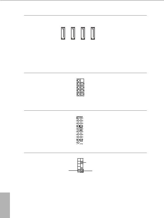
Serial ATA3 Connectors (SATA3_0:
see p.1, No. 10) (SATA3_1: see p.1, No. 11) (SATA3_2: see p.1, No. 12) (SATA3_3: see p.1, No. 13)
SATA3 2 |
SATA3 1 |
SATA3 0 |
These four SATA3 connectors support SATA data cables for internal storage devices with up to 6.0 Gb/s data transfer rate.
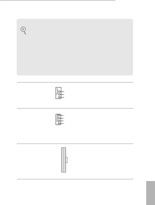
USB 2.0 Headers
(9-pin USB10_11)
(see p.1, No. 8)
DUMMY
GND GND
P+7 P+6
P-7 P-6
USB_PWR USB_PWR
1
Besides two USB 2.0 ports on the I/O panel, there are one header on this motherboard. Each USB 2.0 header can support two ports.
USB 3.0 Headers
(19-pin USB3_5_6)
(see p.1, No. 7)
1
Dummy
IntA_PB_D+
IntA_PB_D-
GND
IntA_PB_SSTX+
IntA_PB_SSTX-
GND
IntA_PB_SSRX+
IntA_PB_SSRX-
Vbus
IntA_PA_D+
IntA_PA_D-
GND
IntA_PA_SSTX+
IntA_PA_SSTX-
GND
IntA_PA_SSRX+
IntA_PA_SSRX-
Vbus
Besides four USB 3.0 ports on the I/O panel, there are one header on this motherboard. Each USB 3.0 header can support two ports.
Front Panel Audio Header
(9-pin HD_AUDIO1)
(see p.1, No. 16)
GN D 
 OUT2_L
J_SENSE
PRESENCE# 
 OUT2_R MIC_RET
 MIC2_R
OUT_RET |
MIC2_L |
1
This header is for connecting audio devices to the front audio panel.
English
24
H87M-ITX
1.High Definition Audio supports Jack Sensing, but the panel wire on the chassis must support HDA to function correctly. Please follow the instructions in our manual and chassis manual to install your system.
2.If you use an AC’97 audio panel, please install it to the front panel audio header by the steps below:
A.Connect Mic_IN (MIC) to MIC2_L.
B.Connect Audio_R (RIN) to OUT2_R and Audio_L (LIN) to OUT2_L.
C.Connect Ground (GND) to Ground (GND).
D.MIC_RET and OUT_RET are for the HD audio panel only. You don’t need to connect them for the AC’97 audio panel.
E.To activate the front mic, go to the “FrontMic” Tab in the Realtek Control panel and adjust “Recording Volume”.
Chassis Fan Connector
(4-pin CHA_FAN1)
(see p.1, No. 14)

 GND +12V
CHA_FAN_SPEED FAN_SPEED_CONTROL
Please connect fan cable to the fan connector and match the black wire to the ground pin.
CPU Fan Connectors |
1 |
|
GN D |
(4-pin CPU_FAN1) |
2 |
|
+ 12V |
|
|
||
(see p.1, No. 6) |
3 |
|
CPU_FAN_SPEED |
4 |
|
FAN_SPEED_CONTROL |
This motherboard provides a 4-Pin CPU fan (Quiet Fan) connector. If you plan to connect a 3-Pin CPU fan, please connect it to Pin 1-3.
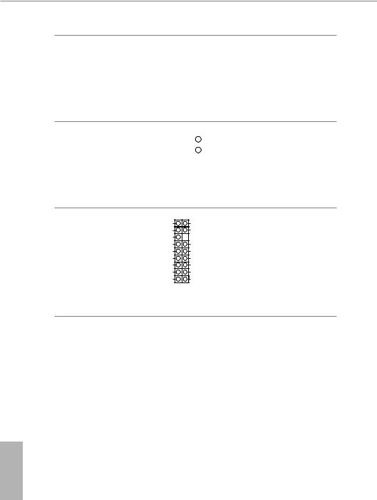
ATX Power Connector
(24-pin ATXPWR1)
(see p.1, No. 5)
12 |
24 |
This motherboard pro- |
|
|
|
vides a 24-pin ATX power |
|
|
|
connector. To use a 20-pin |
|
|
|
ATX power supply, please |
|
1 |
13 |
plug it along Pin 1 and Pin |
|
13. |
|||
|
|
English
25
ATX 12V Power |
|
|
|
|
|
This motherboard pro- |
|
Connector |
|
|
|
|
|
|
vides an 8-pin ATX 12V |
(8-pin ATX12V1) |
|
|
|
|
|
|
power connector. To use a |
|
|
|
|
|
|
||
|
|
|
|
|
|
||
(see p.1, No. 1) |
|
|
|
|
|
4-pin ATX power supply, |
|
|
|
|
|
|
|||
|
|
|
|
|
|
|
please plug it along Pin 1 |
|
|
|
|
|
|
|
and Pin 5. |
Chassis Intrusion Header |
GND |
|
|
|
|
|
|
||
|
|
|
||
(2-pin CI1) |
Signal |
|
|
1 |
|
|
|||
|
|
|||
(see p.1, No. 4) |
|
|
|
|
|
|
|
|
|
This motherboard supports CASE OPEN detection feature that detects if the chassis cove has been removed. This feature requires a chassis with chassis intrusion detection design.
TPM Header
(17-pin TPMS1)
(see p.1, No. 15)
F_CLKRUN# |
GND |
SERIRQ# |
+3VSB |
S_PWRDWN# |
|
GND |
LAD0_L |
LAD1_L |
+3V |
LAD2_L |
LAD3_L |
SMB_DATA_MAIN |
TPM_RST# |
SMB_CLK_MAIN |
LFRAME#_L |
GND |
CK_33M_TPM |
|
1 |
This connector supports Trusted Platform Module (TPM) system, which can securely store keys, digital certificates, passwords, and data. A TPM system also helps enhance network security, protects digital identities, and ensures platform integrity.
English
26

H87M-ITX
1 Einleitung
Vielen Dank, dass Sie sich für das H87M-ITX von ASRock entschieden haben – ein zuverlässiges Motherboard, das konsequent unter der strengen Qualitätskontrolle von ASRock hergestellt wurde. Es liefert ausgezeichnete Leistung mit robustem Design, das ASRocks Streben nach Qualität und Beständigkeit erfüllt.
In dieser Anleitung enthalten Kapitel 1 und 2 die Motherboard-Vorstellung sowie Schritt-für-Schritt-Installationsanleitungen. Kapitel 3 enthält die Bedienungsanleitung von Software und Dienstprogrammen. Kapitel 4 enthält die Konfigurationsanleitung der BIOS-Einrichtung.
Da die technischen Daten des Motherboards sowie die BIOS-Software aktualisiert werden können, kann der Inhalt dieser Dokumentation ohne Ankündigung geändert werden. Falls diese Dokumentation irgendwelchen Änderungen unterliegt, wird die aktualisierte Version ohne weitere Hinweise auf der ASRock-Webseite zur Verfügung gestellt. Sollten Sie technische Hilfe in Bezug auf dieses Motherboard benötigen, erhalten Sie auf unserer Webseite spezifischen Informationen über das von Ihnen verwendete Modell. Auch finden Sie eine aktuelle Liste unterstützter VGA-Karten und Prozessoren auf der ASRockWebseite: ASRock-Webseite http://www.asrock.com.
1.1 Lieferumfang
•ASRock H87M-ITX-Motherboard (Mini-ITX-Formfaktor)
•ASRock H87M-ITX-Schnellinstallationsanleitung
•ASRock H87M-ITX-Support-CD
•2 x Serial-ATA- (SATA) Datenkabel (optional)
•1 x E/A-Blendenabschirmung
Deutsch
27

Deutsch
1.2 Technische Daten
Plattform |
• Mini-ITX-Formfaktor |
|
|
• |
Vollständig solides Kondensatordesign |
Prozessor |
• |
Unterstützt Intel® CoreTM i7 / i5 / i3 / Xeon® / Pentium® / |
|
|
Celeron® der 4. Generation im LGA1150-Paket |
|
• |
4-Leistungsphasendesign |
|
• Unterstützt Intel® Turbo Boost 2.0-Technologie |
|
Chipsatz |
• |
Intel® H87 |
|
• Unterstützt Intel® Small Business Advantage 2.0 |
|
Speicher • Dualkanal-DDR3-Speichertechnologie
•2 x DDR3-DIMM-Steckplätze
•Unterstützt DDR3 1600/1333/1066 non-ECC, ungepufferter Speicher
•Systemspeicher, max. Kapazität: 16 GB (siehe ACHTUNG)
•Unterstützt Intel® Extreme Memory Profile (XMP)1.3/1.2
Erweiterungs- • 1 x PCI-Express 3.0-x16-Steckplatz steckplatz
Grafikkarte • Integrierte Intel® HD Graphics-Visualisierung und VGAAusgänge können nur mit Prozessoren unterstützt werden, die GPU-integriert sind.
•Unterstützt integrierte Intel® HD Graphics-Visualisierung: Intel® Quick Sync Video mit AVC, MVC (S3D) und MPEG-2 Full HW Encode1, Intel® InTruTM 3D, Intel® Clear Video HD Technology, Intel® InsiderTM, Intel® HD Graphics 4400/4600
•Pixel Shader 5.0, DirectX 11.1
•Max. geteilter Speicher: 1792 MB
•Drei VGA-Ausgangsoptionen: D-Sub, DVI-D und HDMI
•Unterstützt drei Monitore
•Unterstützt HDMI-Technologie mit maximaler Auflösung von 1920 x 1200 bei 60 Hz
•Unterstützt DVI-D mit maximaler Auflösung von 1920 x 1200 bei 60 Hz
28

H87M-ITX
• Unterstützt D-Sub mit maximaler Auflösung von 1920 x 1200 bei 60 Hz
• Unterstützt Auto-Lippensynchronizität, hohe Farbtiefe (12
|
|
bpc), xvYCC und HBR (Audio mit hoher Bitrate) mit HDMI |
|
|
(konformer HDMI-Monitor erforderlich) |
|
• Unterstützt HDCP-Funktion mit DVI-D- und HDMI-Ports |
|
|
• Unterstützt Blu-ray- (BD) Wiedergabe (Full HD/1080p) mit |
|
|
|
DVI-D- und HDMI-Ports |
Audio |
• |
7.1-Kanal-HD-Audio mit Inhaltsschutz (Realtek ALC892- |
|
|
Audiocodec) |
|
• |
Erstklassige Blu-ray-Audiounterstützung |
LAN |
• |
PCIE x1 Gigabit LAN 10/100/1000 Mb/s |
|
• |
Qualcomm® Atheros® AR8171 |
|
• Unterstützt Qualcomm® Atheros® Security Wake On Internet- |
|
|
|
Technologie |
|
• |
Unterstützt Wake-On-LAN |
|
• Unterstützt energieeffizientes Ethernet 802.3az |
|
|
• |
Unterstützt PXE |
Rückblende, |
• |
1 x PS/2-Mausanschluss/Tastaturanschluss |
E/A |
• |
1 x D-Sub-Port |
|
• |
1 x DVI-D-Port |
|
• |
1 x HDMI-Port |
|
• 1 x Optischer SPDIF-Ausgang |
|
|
• |
1 x eSATA-Anschluss |
|
• 2 x USB 2.0-Ports |
|
|
• 4 x USB 3.0-Ports |
|
|
• 1 x RJ-45-LAN-Port mit LED (Aktivität/Verbindung-LED und |
|
Geschwindigkeit-LED)
• HD-Audioanschluss: Hintere Lautsprecher / Zentral / Bass / Line-in / Vorderer Lautsprecher / Mikrofon
Deutsch
29
 Loading...