


Copyright Notice:
No part of this installation guide may be reproduced, transcribed, transmitted, or translated in any language, in any form or by any means, except duplication of documentation by the purchaser for backup purpose, without written consent of ASRock Inc.
Products and corporate names appearing in this guide may or may not be registered trademarks or copyrights of their respective companies, and are used only for identification or explanation and to the owners’ benefit, without intent to infringe.
Disclaimer:
Specifications and information contained in this guide are furnished for informational use only and subject to change without notice, and should not be constructed as a commitment by ASRock. ASRock assumes no responsibility for any errors or omissions that may appear in this guide.
With respect to the contents of this guide, ASRock does not provide warranty of any kind, either expressed or implied, including but not limited to the implied warranties or conditions of merchantability or fitness for a particular purpose. In no event shall ASRock, its directors, officers, employees, or agents be liable for any indirect, special, incidental, or consequential damages (including damages for loss of profits, loss of business, loss of data, interruption of business and the like), even if ASRock has been advised of the possibility of such damages arising from any defect or error in the guide or product.
This device complies with Part 15 of the FCC Rules. Operation is subject to the following two conditions:
(1)this device may not cause harmful interference, and
(2)this device must accept any interference received, including interference that may cause undesired operation.
CALIFORNIA, USA ONLY
The Lithium battery adopted on this motherboard contains Perchlorate, a toxic substance controlled in Perchlorate Best Management Practices (BMP) regulations passed by the California Legislature. When you discard the Lithium battery in California, USA, please follow the related regulations in advance.
“Perchlorate Material-special handling may apply, see www.dtsc.ca.gov/hazardouswaste/perchlorate”
ASRock Website: http://www.asrock.com
Published August 2007
Copyright©2007 ASRock INC. All rights reserved.
1
ASRock P4VM890 Motherboard
English

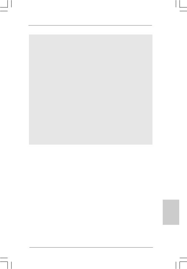
Motherboard Layout
English
1 |
PS2_USB_PWR1 Jumper |
16 |
USB 2.0 Header (USB67, Blue) |
2 |
ATX 12V Connector (ATX12V1) |
17 |
Chassis Speaker Header (SPEAKER 1) |
3 |
CPU Heatsink Retention Module |
18 |
Serial Port Connector (COM1) |
4 |
CPU Socket |
19 |
AMR Slot (AMR1) |
5 |
2 x 184-pin DDR DIMM Slots (DDR1, DDR2; Blue) |
20 |
Clear CMOS Jumper (CLRCMOS1) |
6 |
Infrared Module Header (IR1) |
21 |
JR1 / JL1 Jumpers |
7 |
Flash Memory |
22 |
Front Panel Audio Header (AUDIO1) |
8 |
Floppy Connector (FLOPPY1) |
23 |
Internal Audio Connector: CD1 (Black) |
9 |
Secondary IDE Connector (IDE2, Black) |
24 |
Internal Audio Connector: AUX1 (White) |
10 |
Primary IDE Connector (IDE1, Blue) |
25 |
3 x PCI Slots (PCI1- 3) |
11 |
North Bridge Controller |
26 |
PCI Express x16 Slot (PCIE1) |
12 |
South Bridge Controller |
27 |
Chassis Fan Connector (CHA_FAN1) |
13 |
Primary Serial ATA Connector (SATA1) |
28 |
ATX Power Connector (ATXPWR1) |
14 |
Secondary Serial ATA Connector (SATA2) |
29 |
Shared USB 2.0 Header (USB4_5, Blue) |
15 |
System Panel Header (PANEL1) |
30 |
CPU Fan Connector (CPU_FAN1) |
2
ASRock P4VM890 Motherboard
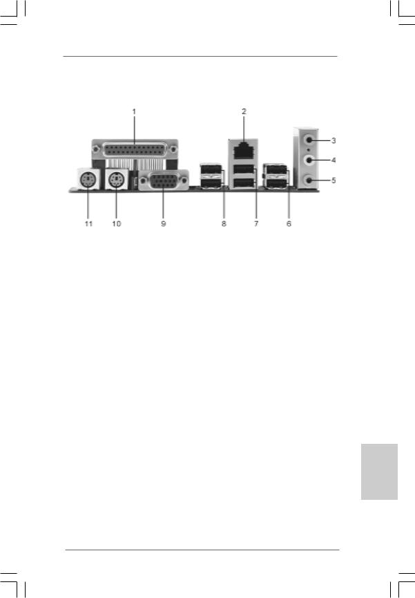
ASRock I/O PlusTM
1 |
Parallel Port |
7 |
USB 2.0 |
Ports (USB01) |
2 |
RJ-45 Port |
8 |
USB 2.0 |
Ports (USB23) |
3 |
Line In (Light Blue) |
9 |
VGA Port |
|
4 |
Line Out (Lime) |
10 |
PS/2 Keyboard Port (Purple) |
|
5 |
Microphone (Pink) |
11 |
PS/2 Mouse Port (Green) |
|
6 |
Shared USB 2.0 Ports (USB45) |
|
|
|
English
3
ASRock P4VM890 Motherboard

1. Introduction
Thank you for purchasing ASRock P4VM890 motherboard, a reliable motherboard produced under ASRock’s consistently stringent quality control. It delivers excellent performance with robust design conforming to ASRock’s commitment to quality and endurance.
This Quick Installation Guide contains introduction of the motherboard and step-by- step installation guide. More detailed information of the motherboard can be found in the user manual presented in the Support CD.
Because the motherboard specifications and the BIOS software might be updated, the content of this manual will be subject to change without notice. In case any modifications of this manual occur, the updated version will be available on ASRock website without further notice. You may find the latest VGA cards and CPU support lists on ASRock website as well.
ASRock website http://www.asrock.com
1.1 Package Contents
ASRock P4VM890 Motherboard
(Micro ATX Form Factor: 9.6-in x 8.0-in, 24.4 cm x 20.3 cm) ASRock P4VM890 Quick Installation Guide
ASRock P4VM890 Support CD
One 80-conductor Ultra ATA 66/100/133 IDE Ribbon Cable One Ribbon Cable for a 3.5-in Floppy Drive
One Serial ATA (SATA) Cable (Optional)
One Serial ATA (SATA) HDD Power Cable (Optional) One ASRock I/O PlusTM Shield
One COM Port Bracket
English
4
ASRock P4VM890 Motherboard
1.2Specifications
Platform |
- Micro ATX Form Factor: 9.6-in x 8.0-in, 24.4 cm x 20.3 cm |
CPU |
- Socket 478 for Intel® Pentium® 4 / Celeron® D (Prescott, |
|
Northwood, Willamate) processors |
|
- FSB 800/533/400 MHz |
|
- Supports Hyper-Threading Technology (see CAUTION 1) |
|
- Supports Untied Overclocking Technology (see CAUTION 2) |
Chipset |
- Northbridge: VIA® P4M890 |
|
- Southbridge: VIA® VT8237R Plus |
Memory |
- 2 x DDR DIMM slots |
|
- Support DDR400/333 |
|
- Max. capacity: 2GB |
Hybrid Booster |
- CPU Frequency Stepless Control (see CAUTION 3) |
|
- ASRock U-COP (see CAUTION 4) |
|
- Boot Failure Guard (B.F.G.) |
Expansion Slot |
- 3 x PCI slots |
|
- 1 x PCI Express x16 slot |
|
- 1 x AMR slot |
Graphics |
- Integrated VIA® UniChrome Pro 3D/2D Graphics |
|
- DirectX 7.0 VGA |
|
- Max. shared memory 64MB |
Audio |
- Realtek ALC653 5.1channel AC’97 audio codec |
LAN |
- VIA® PHY VT6103 |
|
- Speed: 10/100 Ethernet |
|
- Supports Wake-On-LAN |
Rear Panel I/O |
ASRock I/O PlusTM |
|
- 1 x PS/2 Mouse Port |
|
- 1 x PS/2 Keyboard Port |
|
- 1 x VGA Port |
|
- 1 x Parallel Port (ECP/EPP Support) |
|
- 6 x Ready-to-Use USB 2.0 Ports |
|
- 1 x RJ-45 LAN Port |
|
- Audio Jack: Line in/Front Speaker/Microphone |
|
|
Connector |
- 2 x Serial ATA 1.5 Gb/s connectors, support RAID (RAID 0, |
|
RAID 1 and JBOD) and “Hot Plug” functions |
|
- 2 x ATA133 IDE connectors (support 4 x IDE devices) |
|
- 1 x Floppy connector |
|
- 1 x IR header |
|
- 1 x COM port header |
|
- CPU/Chassis FAN connector |
5
ASRock P4VM890 Motherboard
English

|
- 20 pin ATX power connector |
|
- 4 pin 12V power connector |
|
- CD in header |
|
- AUX in header |
|
- Front panel audio connector |
|
- 2 x USB 2.0 headers (support 4 USB 2.0 ports; 2 of them are |
|
shared with USB45 ports on the I/O panel) |
|
(see CAUTION 5) |
BIOS Feature |
- 4Mb AMI BIOS |
|
- AMI Legal BIOS |
|
- Supports “Plug and Play” |
|
- ACPI 1.1 Compliance Wake Up Events |
|
- Supports jumperfree |
|
- AMBIOS 2.3.1 Support |
Support CD |
- Drivers, Utilities, AntiVirus Software (Trial Version) |
Hardware |
- CPU Temperature Sensing |
Monitor |
- Chassis Temperature Sensing |
|
- CPU Fan Tachometer |
|
- Chassis Fan Tachometer |
|
- Voltage Monitoring: +12V, +5V, +3.3V, Vcore |
OS |
- Microsoft® Windows® 2000 / XP compliant |
Certifications |
- FCC, CE, WHQL |
WARNING
Please realize that there is a certain risk involved with overclocking, including adjusting the setting in the BIOS, applying Untied Overclocking Technology, or using the thirdparty overclocking tools. Overclocking may affect your system stability, or even cause damage to the components and devices of your system. It should be done at your own risk and expense. We are not responsible for possible damage caused by overclocking.
English
6
ASRock P4VM890 Motherboard
CAUTION!
1.About the setting of “Hyper Threading Technology”, please check page 26 of “User Manual” in the support CD.
2.This motherboard supports Untied Overclocking Technology. Please read “Untied Overclocking Technology” on page 19 for details.
3.Although this motherboard offers stepless control, it is not recommended to perform over-clocking. Frequencies other than the recommended CPU bus frequencies may cause the instability of the system or damage the CPU.
4.While CPU overheat is detected, the system will automatically shutdown. Before you resume the system, please check if the CPU fan on the motherboard functions properly and unplug the power cord, then plug it back again. To improve heat dissipation, remember to spray thermal grease between the CPU and the heatsink when you install the PC system.
5.Power Management for USB 2.0 works fine under Microsoft® Windows® XP SP1 or SP2 / 2000 SP4.
English
7
ASRock P4VM890 Motherboard

2. Installation
P4VM890 is a Micro ATX form factor (9.6-in x 8.0-in, 24.4 cm x 20.3 cm) motherboard. Before you install the motherboard, study the configuration of your chassis to ensure that the motherboard fits into it.
Pre-installation Precautions
Take note of the following precautions before you install motherboard components or change any motherboard settings.
1.Unplug the power cord from the wall socket before touching any component.
2.To avoid damaging the motherboard components due to static electricity, NEVER place your motherboard directly on the carpet or the like. Also remember to use a grounded wrist strap or touch a safety grounded object before you handle components.
3.Hold components by the edges and do not touch the ICs.
4.Whenever you uninstall any component, place it on a grounded antistatic pad or in the bag that comes with the component.
Before you install or remove any component, ensure that the power is switched off or the power cord is detached from the power supply. Failure to do so may cause severe damage to the motherboard, peripherals, and/or components.
English
8
ASRock P4VM890 Motherboard

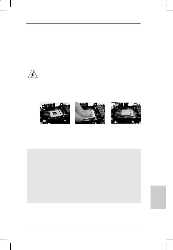
2.1 CPU Installation
Step 1. Unlock the socket by lifting the lever up to a 90° angle.
Step 2. Position the CPU directly above the socket such that its marked corner matches the base of the socket lever.
Step 3. Carefully insert the CPU into the socket until it fits in place.
The CPU fits only in one correct orientation. DO NOT force the
CPU into the socket to avoid bending of the pins.
Step 4. When the CPU is in place, press it firmly on the socket while you push down the socket lever to secure the CPU. The lever clicks on the side tab to indicate that it is locked.
Lift Lever Up to 90°
STEP 1:
Lift The Socket Lever Up to 90°
CPU Marked Corner |
|
Socket Marked Corner |
|
STEP 2/STEP 3: |
STEP 4: |
Match The CPU Marked Corner |
Push Down And Lock |
to The Socket Marked Corner |
TheSocketLever |
2.2 Installation of CPU Fan and Heatsink
This motherboard adopts 478-pin CPU socket to support Intel® Pentium® 4 / Celeron® CPU. It requires larger heatsink and cooling fan to dissipate heat. You also need to spray thermal grease between the CPU and the heatsink to improve heat dissipation. Make sure that the CPU and the heatsink are securely fastened and in good contact with each other. Then connect the CPU fan to the CPU_FAN connector (CPU_FAN1, see p.2 No. 30). For proper installation, please kindly refer to the instruction manuals of the CPU fan and the heatsink.
English
9
ASRock P4VM890 Motherboard
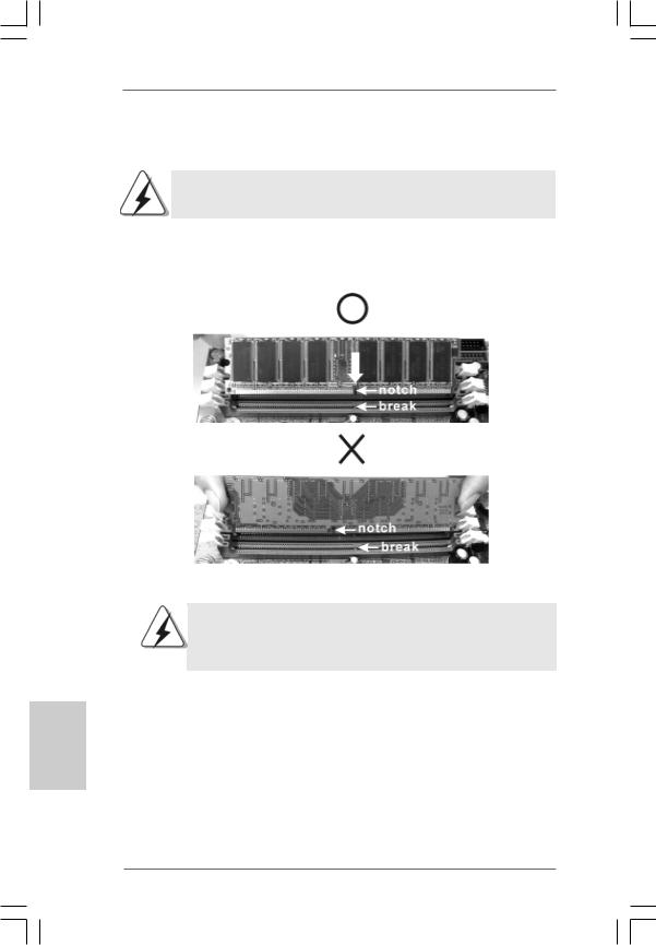
2.3 Installation of Memory Modules (DIMM)
P4VM890 motherboard provides two 184-pin DDR (Double Data Rate) DIMM slots.
Please make sure to disconnect power supply before adding or removing
DIMMs or the system components.
Step 1. Unlock a DIMM slot by pressing the retaining clips outward.
Step 2. Align a DIMM on the slot such that the notch on the DIMM matches the break on the slot.
The DIMM only fits in one correct orientation. It will cause permanent damage to the motherboard and the DIMM if you force the DIMM into the slot at incorrect orientation.
Step 3. Firmly insert the DIMM into the slot until the retaining clips at both ends fully snap back in place and the DIMM is properly seated.
English
1 0
ASRock P4VM890 Motherboard
2.4 Expansion Slots (PCI, AMR and PCI Express Slots)
There are 3 PCI slots, 1 AMR slot, and 1 PCI Express slot on this motherboard. PCI slots: PCI slots are used to install expansion cards that have the 32-bit PCI
interface.
AMR slot: The AMR slot is used to insert an ASRock MR card with v.92 Modem functionality.
PCIE Slots: PCIE1 (PCIE x16 slot) is used for PCI Express cards with x16 lane width graphics cards.
Installing an expansion card
Step 1. Before installing the expansion card, please make sure that the power supply is switched off or the power cord is unplugged. Please read the documentation of the expansion card and make necessary hardware settings for the card before you start the installation.
Step 2. Remove the system unit cover (if your motherboard is already installed in a chassis).
Step 3. Remove the bracket facing the slot that you intend to use. Keep the screws for later use.
Step 4. Align the card connector with the slot and press firmly until the card is completely seated on the slot.
Step 5. Fasten the card to the chassis with screws. Step 6. Replace the system cover.
English
1 1
ASRock P4VM890 Motherboard
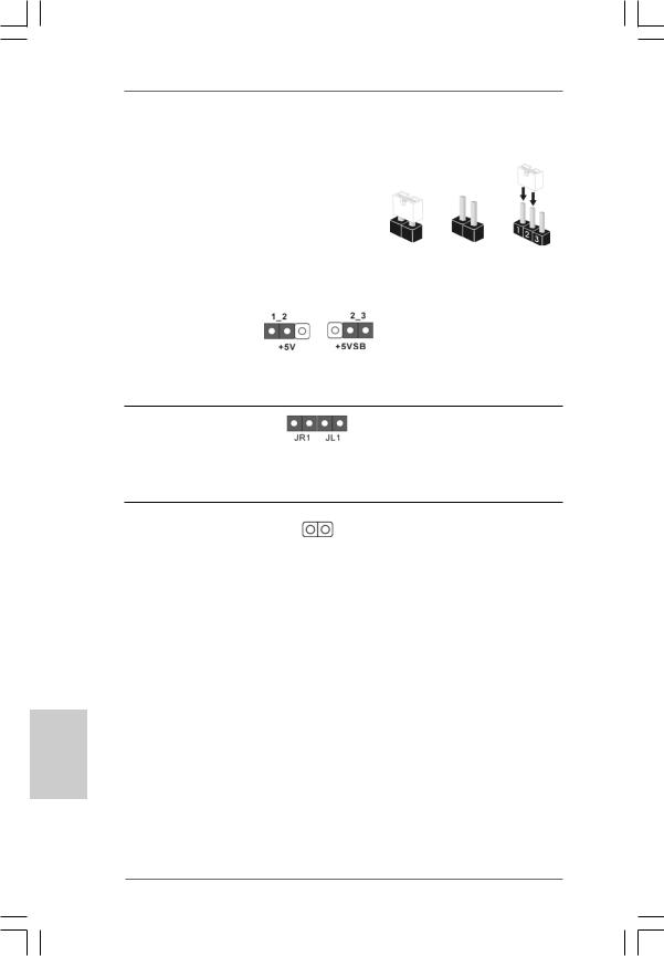
2.5 Jumpers Setup
The illustration shows how jumpers are |
|
|
setup. When the jumper cap is placed on |
|
|
pins, the jumper is “Short”. If no jumper cap |
|
|
is placed on pins, the jumper is “Open”. The |
|
|
illustration shows a 3-pin jumper whose pin1 |
|
|
and pin2 are “Short” when jumper cap is |
Open |
|
placed on these 2 pins. |
Short |
|
|
|
|
Jumper |
Setting |
|
PS2_USB_PWR1 |
Short pin2, pin3 to enable |
|
(see p.2, No. 1) |
+5VSB (standby) for PS/2 |
|
|
or USB wake up events. |
|
Note: To select +5VSB, it requires 2 Amp and higher standby current provided by power supply.
JR1(see p.2, No. 21)
JL1(see p.2, No. 21)
Note: If the jumpers JL1 and JR1 are short, both the front panel and the rear panel audio connectors can work.
Clear CMOS
(CLRCMOS1, 2-pin jumper)
(see p.2, No. 24)
2-pin jumper
Note: CLRCMOS1 allows you to clear the data in CMOS. The data in CMOS includes system setup information such as system password, date, time, and system setup parameters. To clear and reset the system parameters to default setup, please turn off the computer and unplug the power cord from the power supply. After waiting for 15 seconds, use a jumper cap to short 2 pins on CLRCMOS1 for 5 seconds.
English
1 2
ASRock P4VM890 Motherboard
2.6 Onboard Headers and Connectors
Onboard headers and connectors are NOT jumpers. Do NOT place jumper caps over these headers and connectors. Placing jumper caps over the headers and connectors will cause permanent damage of the motherboard!
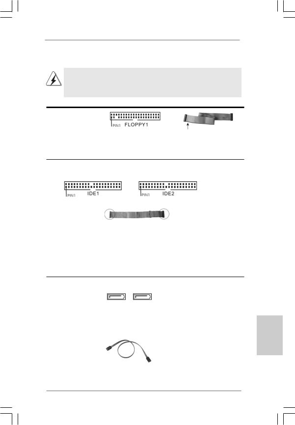
FDD Connector
(33-pin FLOPPY1)
(see p.2, No. 8)
the red-striped side to Pin1
Note: Make sure the red-striped side of the cable is plugged into Pin1 side of the connector.
Primary IDE Connector (Blue) |
Secondary IDE Connector (Black) |
(39-pin IDE1, see p.2, No. 10) |
(39-pin IDE2, see p.2, No. 9) |
connect the blue end |
connect the black end |
to the motherboard |
to the IDE devices |
80-conductor ATA 66/100/133 cable
Note: If you use only one IDE device on this motherboard, please set the IDE device as “Master”. Please refer to the instruction of your IDE device vendor for the details. Besides, to optimize compatibility and performance, please connect your hard disk drive to the primary IDE connector (IDE1, blue) and CD-ROM to the secondary IDE connector (IDE2, black).
Serial ATA Connectors |
|
These two Serial ATA (SATA) |
(SATA1: see p.2, No. 13) |
|
connectors support SATA data |
(SATA2: see p.2, No. 14) |
|
cables for internal storage |
SATA2 |
SATA1 |
devices. The current SATA |
|
|
|
|
|
interface allows up to 1.5 Gb/s |
|
|
data transfer rate. |
|
|
|
Serial ATA (SATA) |
|
Either end of the SATA data |
Data Cable |
|
cable can be connected to the |
(Optional) |
|
SATA hard disk or the SATA |
|
|
connector on the motherboard. |
English
1 3
ASRock P4VM890 Motherboard
English
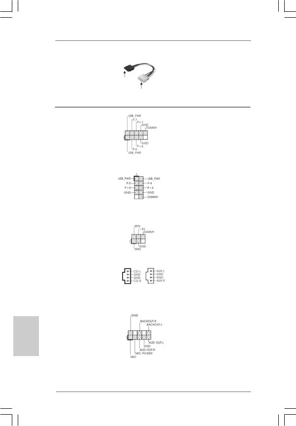
Serial ATA (SATA)
Power Cable
(Optional)
connect to the SATA
HDD power connector
connect to the powersupply
Please connect the black end of SATA power cable to the power connector on the drive. Then connect the white end of SATA power cable to the power connector of the power supply.
USB 2.0 Header |
|
|
Besides six default USB 2.0 |
(9-pin USB67) |
|
|
ports on the I/O panel, there are |
(see p.2, No. 16) |
|
|
two USB 2.0 headers on this |
|
|
|
motherboard. Each USB 2.0 |
|
|
|
header can support two USB |
|
|
|
2.0 ports. The shared USB 2.0 |
|
|
|
header (USB4_5) is shared with |
Shared USB 2.0 Header |
|
|
USB ports 45 on the I/O panel. |
(9-pin USB4_5) |
|
|
When using the front panel USB |
(see p.2, No. 29) |
|
|
ports by attaching the front panel |
|
|
|
USB cable to USB4_5 header, |
|
|
|
the USB ports 45 on the I/O panel |
|
|
|
will not be able to function. |
|
|
|
|
Infrared Module Header |
|
|
This header supports an optional |
(5-pin IR1) |
|
|
wireless transmitting and |
(see p.2, No. 6) |
|
|
receiving infrared module. |
|
|
|
|
Internal Audio Connectors |
|
|
These connectors allow you |
(4-pin CD1, 4-pin AUX1) |
|
|
to receive stereo audio input |
(CD1: see p.2, No. 23) |
|
|
from sound sources such as |
(AUX1: see p.2, No. 24) |
CD1 |
AUX1 |
a CD-ROM, DVD-ROM, TV |
|
tuner card, or MPEG card. |
||
|
|
|
|
|
|
|
|
Front Panel Audio Header |
|
|
This is an interface for the front |
(8-pin AUDIO1) |
|
|
panel audio cable that allows |
(see p.2, No. 22) |
|
|
convenient connection and |
|
|
|
control of audio devices. |
1 4
ASRock P4VM890 Motherboard
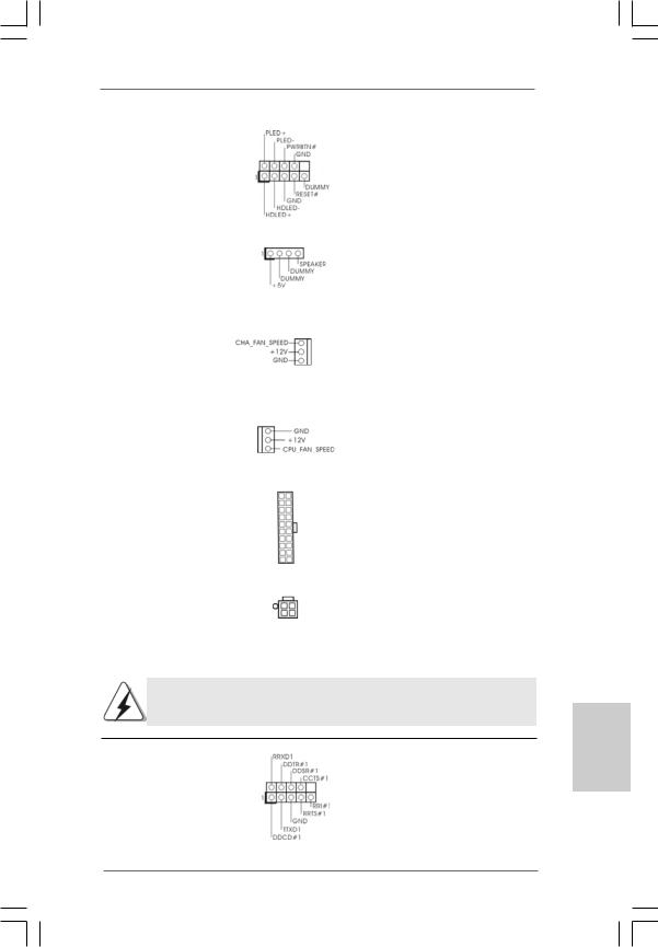
System Panel Header |
This header accommodates |
(9-pin PANEL1) |
several system front panel |
(see p.2, No. 15) |
functions. |
|
|
Chassis Speaker Header |
Please connect the chassis |
(4-pin SPEAKER 1) |
speaker to this header. |
(see p.2, No. 17) |
|
|
|
Chassis Fan Connector |
Please connect the chassis fan |
(3-pin CHA_FAN1) |
cable to this connector and |
(see p.2, No. 27) |
match the black wire to the |
|
ground pin. |
|
|
CPU Fan Connector |
Please connect the CPU fan |
(3-pin CPU_FAN1) |
cable to this connector and |
(see p.2, No. 30) |
match the black wire to the |
|
ground pin. |
|
|
ATX Power Connector |
Please connect an ATX power |
(20-pin ATXPWR1) |
supply to this connector. |
(see p.2, No. 28) |
|
|
|
ATX 12V Connector |
Please note that it is necessary |
(4-pin ATX12V1) |
to connect a power supply with |
(see p.2, No. 2) |
ATX 12V plug to this connector |
|
so that it can provides sufficient |
|
power. Failing to do so will cause |
|
the failure to power up. |
Please install the heatsink and the CPU fan before installing ATX 12V connector; otherwise, it may cause permanent damage!
Serial port connector |
This COM1 connector |
(9-pin COM1) |
supports a serial port module. |
(see p.2, No. 18) |
|
English
1 5
ASRock P4VM890 Motherboard

English
2.7 Serial ATA (SATA) Hard Disks Installation
This motherboard adopts VIA® VT8237R Plus southbridge chipset that supports Serial ATA (SATA) hard disks and RAID (RAID 0, RAID 1 and JBOD) functions. You may install SATA hard disks on this motherboard for internal storage devices. This section will guide you to install the SATA hard disks.
STEP 1: Install the SATA hard disks into the drive bays of your chassis. STEP 2: Connect the SATA power cable to the SATA hard disk.
STEP 3: Connect one end of the SATA data cable to the motherboard’s SATA connector.
STEP 4: Connect the other end of the SATA data cable to the SATA hard disk.
2.8 Hot Plug and Hot Swap Functions for SATA HDDs
P4VM890 motherboard supports Hot Plug and Hot Swap functions for SATA Devices.
NOTE
What is Hot Plug Function?
If the SATA HDDs are NOT set for RAID configuration, it is called “Hot Plug” for the action to insert and remove the SATA HDDs while the system is still power-on and in working condition.
However, please note that it cannot perform Hot Plug if the OS has been installed into the SATA HDD.
What is Hot Swap Function?
If SATA HDDs are built as RAID1 then it is called “Hot Swap” for the action to insert and remove the SATA HDDs while the system is still power-on and in working condition.
2.9Driver Installation Guide
To install the drivers to your system, please insert the support CD to your optical drive first. Then, the drivers compatible to your system can be auto-detected and listed on the support CD driver page. Please follow the order from up to bottom side to install those required drivers. Therefore, the drivers you install can work properly.
1 6
ASRock P4VM890 Motherboard

2.10 AMR Card and Driver Installation
If you do not insert AMR card to this motherboard, and you finish installing all drivers to your system now, but in the future, you plan to use AMR card function on this motherboard, please follow the steps below then.
1.Insert AMR card to AMR slot on this motherboard. Please make sure that the AMR card is completely seated on the slot.
2.Install AMR card driver from our support CD to your system.
3.Reboot your system.
2.11 Installing Windows® 2000 / XP With RAID Functions
If you want to install Windows® 2000 / Windows® XP OS on your SATA
HDDs with RAID functions, please follow below steps.
STEP 1: Set up BIOS.
A. |
Enter BIOS SETUP UTILITY |
|
Advanced screen |
|
IDE Configuration. |
|
|
||||
B. |
Set the “SATA Operation Mode” option to [RAID]. |
|
|
||
STEP 2: Make a SATA driver diskette.
A. |
Insert the ASRock Support CD into your optical drive to boot your system. |
B.During POST at the beginning of system boot-up, press <F11> key, and then a window for boot devices selection appears. Please select CDROM as the boot device.
C.When you see the message on the screen, “Generate Serial ATA driver diskette [YN]?”, press <Y>.
D.Then you will see these messages,
Please insert a blank formatted diskette into floppy drive A:
press any key to start
Please insert a floppy diskette into the floppy drive, and press any key.
E.The system will start to format the floppy diskette and copy SATA drivers into the floppy diskette.
STEP 3: Use “RAID Installation Guide” to set RAID configuration.
Before you start to configure RAID function, you need to check the RAID installation guide in the Support CD for proper configuration. Please refer to the document in the following path in the Support CD:
.. \ RAID Installation Guide
STEP 4: Install Windows® 2000 / XP OS on your system.
After step1, 2, 3, you can start to install Windows® 2000 / Windows® XP OS on your system. At the beginning of Windows® setup, press F6 to install a third-party RAID driver. When prompted, insert the SATA driver diskette containing the VIA® RAID driver. After reading the floppy disk, the driver will be presented. Select the driver to install according to the mode you choose and the OS you install.
1 7
ASRock P4VM890 Motherboard
English

NOTE. If you install Windows® 2000 / Windows® XP on IDE HDDs and want to manage (create, convert, delete, or rebuild) RAID functions on SATA HDDs, you still need to set up “SATA Operation Mode” to [RAID] in BIOS first. Then, please set the RAID configuration by using the document in the following path in the Support CD:
.. \ RAID Installation Guide
If you want to use “VIA RAID Tool” in Windows® environment, please install SATA drivers from the Support CD again so that “VIA RAID Tool” will be installed to your system as well.
2.12 Installing Windows® 2000 / XP Without RAID Functions
If you want to install Windows® 2000 / XP on your SATA HDDs without RAID functions, please follow below steps.
STEP 1: Set up BIOS.
A. |
Enter BIOS SETUP UTILITY |
|
Advanced screen |
|
|
IDE Configuration. |
|
|
|||||
B. |
Set the “SATA Operation Mode” option to [non-RAID]. |
|
||||
STEP 2: Install Windows® 2000 / XP OS on your system.
After setting up BIOS, you can start to install Windows® 2000 / XP on your system.
English
1 8
ASRock P4VM890 Motherboard

2.13 Untied Overclocking Technology
This motherboard supports Untied Overclocking Technology, which means during overclocking, FSB enjoys better margin due to fixed PCI / PCIE bus. You may set “CPU Host Frequency” option of BIOS setup to [Auto], which will show you the actual CPU host frequency in the following item. Therefore, CPU FSB is untied during overclocking, but PCI / PCIE bus is in the fixed mode so that FSB can operate under a more stable overclocking environment.
Please refer to the warning on page 6 for the possible overclocking risk before you apply Untied Overclocking Technology.
3. BIOS Information
The Flash Memory on the motherboard stores BIOS Setup Utility. When you start up the computer, please press <F2> during the Power-On-Self-Test (POST) to enter BIOS Setup utility; otherwise, POST continues with its test routines. If you wish to enter BIOS Setup after POST, please restart the system by pressing <Ctl> + <Alt> + <Delete>, or pressing the reset button on the system chassis.
The BIOS Setup program is designed to be user-friendly. It is a menu-driven program, which allows you to scroll through its various sub-menus and to select among the predetermined choices. For the detailed information about BIOS Setup, please refer to the User Manual (PDF file) contained in the Support CD.
4. Software Support CD information
This motherboard supports various Microsoft® Windows® operating systems: 2000 / XP. The Support CD that came with the motherboard contains necessary drivers and useful utilities that will enhance motherboard features.
To begin using the Support CD, insert the CD into your CD-ROM drive. It will display the Main Menu automatically if “AUTORUN” is enabled in your computer. If the Main Menu does not appear automatically, locate and double-click on the file “ASSETUP.EXE” from the BIN folder in the Support CD to display the menus.
English
1 9
ASRock P4VM890 Motherboard
1. Einführung
Wir danken Ihnen für den Kauf des ASRock P4VM890 Motherboard, ein zuverlässiges Produkt, welches unter den ständigen, strengen Qualitätskontrollen von ASRock gefertigt wurde. Es bietet Ihnen exzellente Leistung und robustes Design, gemäß der Verpflichtung von ASRock zu Qualität und Halbarkeit.
Diese Schnellinstallationsanleitung führt in das Motherboard und die schrittweise Installation ein. Details über das Motherboard finden Sie in der Bedienungsanleitung auf der Support-CD.
Da sich Motherboard-Spezifikationen und BIOS-Software verändern können, kann der Inhalt dieses Handbuches ebenfalls jederzeit geändert werden. Für den Fall, dass sich Änderungen an diesem Handbuch ergeben, wird eine neue Version auf der ASRock-Website, ohne weitere Ankündigung, verfügbar sein. Die neuesten Grafikkarten und unterstützten CPUs sind auch auf der ASRock-Website aufgelistet.
ASRock-Website: http://www.asrock.com
1.1 Kartoninhalt
ASRock P4VM890 Motherboard
(Micro ATX-Formfaktor: 24.4 cm x 20.3 cm; 9.6 Zoll x 8.0 Zoll) ASRock P4VM890 Schnellinstallationsanleitung
ASRock P4VM890 Support-CD
Ein 80-adriges Ultra-ATA 66/100/133 IDE-Flachbandkabel Ein Flachbandkabel für ein 3,5-Zoll-Diskettenlaufwerk Ein Seriell-ATA- (SATA) Datenkabel (Option)
Ein Seriell-ATA (SATA) Festplattennetzkabel (Option) Ein ASRock I/O PlusTM Shield
Ein COM Port-Anschlusshalter (Option)
Deutsch
2 0
ASRock P4VM890 Motherboard
1.2Spezifikationen
Plattform |
- Micro ATX-Formfaktor: 24.4 cm x 20.3 cm; 9.6 Zoll x 8.0 Zoll |
|
|
CPU |
- Socket 478 für Intel® Pentium® 4 / Celeron® D (Prescott, |
|
|
|
Northwood, Willamate) Prozessoren |
|
|
|
- FSB 800/533/400 MHz |
|
|
|
- Unterstützt Hyper-Threading-Technologie |
|
|
|
(siehe VORSICHT 1) |
|
|
|
- Unterstützt Untied-Übertaktungstechnologie |
|
|
|
(siehe VORSICHT 2) |
|
|
Chipsatz |
- Northbridge: VIA® P4VM890 |
|
|
|
- Southbridge: VIA® VT8237R Plus |
|
|
Speicher |
- 2 x Steckplätze für DDR |
|
|
|
- Unterstützt DDR400/333 |
|
|
|
- Max. 2GB |
|
|
Hybrid Booster |
- Schrittloser CPU-Frequenz-Kontrolle (siehe VORSICHT 3) |
|
|
|
- ASRock U-COP (siehe VORSICHT 4) |
|
|
|
- Boot Failure Guard (B.F.G. – Systemstartfehlerschutz) |
|
|
Erweiterungs- |
- 3 x PCI -Steckplätze |
|
|
steckplätze |
- 1x PCI Express x16 -Steckplätze |
|
|
|
- 1 x AMR -Steckplätze |
|
|
Onboard-VGA |
- Integrierte VIA® UniChrome Pro 3D/2D Graphik |
|
|
|
- DirectX 7.0 VGA |
|
|
|
- Maximal gemeinsam genutzter Speicher 64MB |
|
|
Audio |
- Realtek ALC653 5.1Kanal AC’97 Audio Codec |
|
|
LAN |
- VIA® PHY VT6103 |
|
|
|
- Speed: 10/100 Ethernet |
|
|
|
- Unterstützt Wake-On-LAN |
|
|
E/A-Anschlüsse |
ASRock I/O PlusTM |
|
|
an der |
- 1 x PS/2 Mouse Port |
|
|
Rückseite |
- 1 x PS/2 Keyboard Port |
|
|
|
- 1 x VGA Port |
|
|
|
- 1 x Parallel Port (ECP/EPP Support) |
|
|
|
- 6 x Ready-to-Use USB 2.0 Ports |
|
Deutsch |
|
- 1 x RJ-45 Port |
|
|
|
|
|
|
|
- Audioanschlüsse: Line In / Line Out / Mikrofon |
|
|
|
|
|
|
|
|
|
|
2 1
ASRock P4VM890 Motherboard
Deutsch
Anschlüsse |
- 2 x Serial ATA 1.5 Gb/s Anschlüsse, unterstützt RAID (RAID 0, |
|
RAID 1 und JBOD) und “Hot Plug” Funktionen |
|
- 2 x ATA133 IDE-Anschlüsse (Unterstützt bis 4 IDE-Geräte) |
|
- 1 x FDD-Anschlüsse |
|
- 1 x Infrarot-Modul-Header |
|
- 1 x COM-Anschluss-Header |
|
- CPU/Gehäuse-Lüfteranschluss |
|
- 20-pin ATX-Netz-Header |
|
- 4-pin anschluss für 12V-ATX-Netzteil |
|
- Interne Audio-Anschlüsse |
|
- Anschluss für Audio auf der Gehäusevorderseite |
|
- 2 x USB 2.0 Headers (unterstützt 4 USB 2.0 Ports; 2 davon |
|
sind geteilt mit USB45 Ports auf dem I/O Panel) |
|
(siehe VORSICHT 5) |
BIOS |
- 4Mb AMI BIOS |
|
- AMI legal BIOS mit Unterstützung für “Plug and Play” |
|
- ACPI 1.1-Weckfunktionen |
|
- JumperFree-Modus |
|
- SMBIOS 2.3.1 |
Support-CD |
- Treiber, Dienstprogramme, Antivirussoftware |
|
(Probeversion) |
Hardware Monitor |
- Überwachung der CPU-Temperatur |
|
- Motherboardtemperaturerkennung |
|
- Drehzahlmessung für CPU-Lüfter |
|
- Drehzahlmessung für Gehäuselüfter |
|
- Spannungsüberwachung: +12V, +5V, +3.3V, Vcore |
Betriebssysteme |
- Unterstützt Microsoft® Windows® 2000 / XP |
Zertifizierungen |
- FCC, CE, WHQL |
|
|
WARNUNG
Beachten Sie bitte, dass Overclocking, einschließlich der Einstellung im BIOS, Anwenden der Untied Overclocking-Technologie oder Verwenden von Overclocking-Werkzeugen von Dritten, mit einem gewissen Risiko behaftet ist. Overclocking kann sich nachteilig auf die Stabilität Ihres Systems auswirken oder sogar Komponenten und Geräte Ihres Systems beschädigen. Es geschieht dann auf eigene Gefahr und auf Ihre Kosten. Wir übernehmen keine Verantwortung für mögliche Schäden, die aufgrund von Overclocking verursacht wurden.
2 2
ASRock P4VM890 Motherboard
VORSICHT!
1.Die Einstellung der “Hyper-Threading Technology”, finden Sie auf Seite 26 des auf der Support-CD enthaltenen Benutzerhandbuches beschrieben.
2.Dieses Motherboard unterstützt die Untied-Übertaktungstechnologie. Unter “Entkoppelte Übertaktungstechnologie” auf Seite 36 finden Sie detaillierte Informationen.
3.Obwohl dieses Motherboard stufenlose Steuerung bietet, wird Overclocking nicht empfohlen. Frequenzen, die über den für den jeweiligen Prozessor vorgesehenen liegen, können das System instabil werden lassen oder die CPU beschädigen.
4.Wird eine Überhitzung der CPU registriert, führt das System einen automatischen Shutdown durch. Bevor Sie das System neu starten, prüfen Sie bitte, ob der CPU-Lüfter am Motherboard richtig funktioniert, und stecken Sie bitte den Stromkabelstecker aus und dann wieder ein. Um die Wärmeableitung zu verbessern, bitte nicht vergessen, etwas Wärmeleitpaste zwischen CPU und Kühlkörper zu sprühen.
5.Das Power Management für USB 2.0 arbeitet unter Microsoft® Windows® XP SP1 oder SP2/2000 SP4 einwandfrei.
Deutsch
2 3
ASRock P4VM890 Motherboard
2. Installation
P4VM890 ist ein Mikro ATX Formfaktor (9.6-in x 8.0-in, 24.4 cm x 20.3 cm) Hauptplatine. Bevor Sie die Hauptplatine installieren, lesen Sie die Konfiguration des Gehäuses und vergewissern Sie sich, ob die Hauptplatine in ihm passt.
Sicherheitshinweise vor der Montage
Bitte nehmen Sie die folgende Sicherheitshinweise zur Kenntnis, bevor Sie das Motherboard einbauen oder Veränderungen an den Einstellungen vornehmen.
1.Trennen Sie das System vom Stromnetz, bevor Sie eine
Systemkomponente berühren, da es sonst zu schweren Schäden am Motherboard oder den sonstigen internen, bzw. externen Komponenten kommen kann.
2.Um Schäden aufgrund von statischer Elektrizität zu vermeiden, das Motherboard NIEMALS auf einen Teppich o.ä.legen. Denken Sie außerem daran, immer ein geerdetes Armband zu tragen oder ein geerdetes Objekt aus Metall zu berühren, bevor Sie mit Systemkomponenten hantieren.
3.Halten Sie Komponenten immer an den Rändern und vermeiden Sie Berührungen mit den ICs.
4.Wenn Sie irgendein Bauteil deinstallieren, legen Sie es auf eine geerdete antistatische Unterlage oder in die Tasche, in der dieses Bauteil geliefert wurde.
Bevor Sie irgendein Bauteil installieren oder abbauen, vergewissern Sie sich, daß der Netzstrom ausgeschaltet ist oder das Stromkabel nicht mit der Netz angeschlossen ist. Fehler dabei kann zum schwerwiegenden Schaden an Hauptplatine, Peripherien und/oder Bauteile führen.
Deutsch
2 4
ASRock P4VM890 Motherboard
2.1 CPU Installation
Schritt 1. |
Entriegeln Sie die Steckdose durch Hochziehen des Hebels bis zu |
|||
|
|
einer 90 Winkel. |
|
|
Schritt 2. |
Positionieren Sie die CPU direct über die Steckdose so, daß ihre |
|||
|
|
markierte Ecke den Sockel des Dosehebels passt. |
||
Schritt 3. |
Stecken Sie die CPU vorsichtig in den Sockel hinein, bis sie in der |
|||
|
|
Stelle passt. |
|
|
|
|
|
||
|
|
Die CPU passt nur in einer Richtung. Zwingen Sie die CPU nicht in den Sockel |
||
|
|
ab, um die Biegung der Pins zu vermeiden. |
|
|
|
|
|
||
Schritt 4. |
Wenn die CPU an der Stelle ist, dann drücken Sie sie fest auf der |
|||
|
|
Dose während Sie den Dosehebel hinrunter drücken. Der Hebel klickt |
||
|
|
auf der Seitenklappe und das zeigt, daß sie verriegelt ist. |
||
|
|
|
Markierte Ecke der CPU |
|
|
|
Den Hebel bis zum 90 |
|
|
|
|
hochziehen |
Markierte Ecke des Sockels |
|
|
SCHRITT 1: |
SCHRITT 2/ SCHRITT 3: |
SCHRITT 4: |
|
|
Den Hebel des Sockels bis zum |
Die markierte Ecke der CPU |
Den Hebel des Sockels |
|
90 |
hochziehen. |
zu der markierten Ecke des |
runterdrücken und verriegeln. |
|
|
|
|
Sockelsanpassen. |
|
2.2Installation des CPU-Lüfters und des Kühlkörpers
Diese Hauptplatine adotpiert 478-pin CPU Sockel zur Unterstützung der Intel® Pentium® 4 / Celeron® CPU. Es erfordert große Kühlwinkel und Ventilator, um die Hitze abzuführen. Sie brauchen auch thermales Schmiermittel zwischen der CPU und der Kühlwinkel zu sprühen, um die Abführung der Hitze zu verbessern. Vergewissern Sie sich, daß die CPU und Kühlwinkel fest zusammen befestigt und in gutem Kontakt miteinanderen sind. Danach verbinden Sie die CPU Ventilator mit der CPU_Ventilator Anschlußstück (CPU_FAN1, siehe S.2 No. 30). Für die korrekte Installation bitte lesen Sie die Gebrauchanweisung der CPU Ventilator und der Kühlwinkel.
Deutsch
2 5
ASRock P4VM890 Motherboard

2.3 Installation der Speichermodule (DIMM)
Das P4VM890-Motherboard hat zwei 184-pol. DDR- (Double Data Rate) DIMMSteckplätze.
Achten Sie darauf, das Netzteil abzustecken, bevor Sie DIMMs oder
Systemkomponenten hinzufügen oder entfernen.
Schritt 1: Öffnen Sie einen DIMM-Slot, indem Sie die seitlichen Clips nach außen drücken.
Schritt 2: Richten Sie das DIMM-Modul so über dem Slot aus, dass das Modul mit der Kerbe in den Slot passt.
Die DIMM-Module passen nur richtig herum eingelegt in die Steckplätze.
Falls Sie versuchen, die DIMM-Module mit Gewalt falsch herum in die
Steckplätze zu zwingen, führt dies zu dauerhaften Schäden am
Mainboard und am DIMM-Modul.
Schritt 3: Drücken Sie die DIMM-Module fest in die Steckplätze, so dass die Halteklammern an beiden Enden des Moduls einschnappen und das DIMM-Modul fest an Ort und Stelle sitzt.
Deutsch
2 6
ASRock P4VM890 Motherboard

2.4 Erweiterungssteckplätze: (PCI-, AMR-, und PCI ExpressSlots):
Es stehen 3 PCI-, 1 AMR-, und 1 PCI Express-Slot auf dem P4VM890 Motherboard zur Verfügung.
PCI-Slots: PCI-Slots werden zur Installation von Erweiterungskarten mit dem 32bit PCI-Interface genutzt.
AMR-Slot: Der AMR-Steckplatz dient zur Aufnahme der ASRock MR-Karte mit v.92 Modem-Funktionalität.
PCI Express-Slots: PCIE1 (PCIE x16-Steckplatz) wird für PCI ExpressGrafikkarten mit x16-Busbreite verwendet.
Einbau einer Erweiterungskarte
Schritt 1: Bevor Sie die Erweiterungskarte installieren, vergewissern Sie sich, dass das Netzteil ausgeschaltet und das Netzkabel abgezogen ist. Bitte lesen Sie die Dokumentation zur Erweiterungskarte und nehmen Sie nötige Hardware-Einstellungen für die Karte vor, ehe Sie mit der Installation beginnen.
Schritt 2: Entfernen Sie das Abdeckungsblech (Slotblende) von dem Gehäuseschacht (Slot) , den Sie nutzen möchten und behalten die Schraube für den Einbau der Karte.
Schritt 3: Richten Sie die Karte über dem Slot aus und drücken Sie sie ohne Gewalt hinein, bis sie den Steckplatz korrekt ausfüllt.
Schritt 4: Befestigen Sie die Karte mit der Schraube aus Schritt 2.
Deutsch
2 7
ASRock P4VM890 Motherboard
 Loading...