


Copyright Notice:
No part of this installation guide may be reproduced, transcribed, transmitted, or translated in any language, in any form or by any means, except duplication of documentation by the purchaser for backup purpose, without written consent of ASRock Inc.
Products and corporate names appearing in this guide may or may not be registered trademarks or copyrights of their respective companies, and are used only for identification or explanation and to the owners’ benefit, without intent to infringe.
Disclaimer:
Specifications and information contained in this guide are furnished for informational use only and subject to change without notice, and should not be constructed as a commitment by ASRock. ASRock assumes no responsibility for any errors or omissions that may appear in this guide.
With respect to the contents of this guide, ASRock does not provide warranty of any kind, either expressed or implied, including but not limited to the implied warranties or conditions of merchantability or fitness for a particular purpose. In no event shall ASRock, its directors, officers, employees, or agents be liable for any indirect, special, incidental, or consequential damages (including damages for loss of profits, loss of business, loss of data, interruption of business and the like), even if ASRock has been advised of the possibility of such damages arising from any defect or error in the guide or product.
This device complies with Part 15 of the FCC Rules. Operation is subject to the following two conditions:
(1)this device may not cause harmful interference, and
(2)this device must accept any interference received, including interference that may cause undesired operation.
CALIFORNIA, USA ONLY
The Lithium battery adopted on this motherboard contains Perchlorate, a toxic substance controlled in Perchlorate Best Management Practices (BMP) regulations passed by the California Legislature. When you discard the Lithium battery in California, USA, please follow the related regulations in advance.
“Perchlorate Material-special handling may apply, see www.dtsc.ca.gov/hazardouswaste/perchlorate”
ASRock Website: http://www.asrock.com
Published May 2009
Copyright©2009 ASRock INC. All rights reserved.
1
English
ASRock N68-S Motherboard

Motherboard Layout
English
2
1 |
PS2_USB_PW1 Jumper |
15 |
Chassis Speaker Header |
2 |
CPU Fan Connector (CPU_FAN1) |
|
(SPEAKER 1, Purple) |
3 |
2 x 240-pin DDR2 DIMM Slots |
16 |
USB 2.0 Header (USB6_7, Blue) |
|
(Dual Channel: DDRII_1, DDRII_2; Yellow) |
17 |
System Panel Header (PANEL1, Orange) |
4 |
ATX Power Connector (ATXPWR1) |
18 |
Print Port Header (LPT1, Purple) |
5 |
SATAII Connector (SATAII_2 (PORT 1.1)) |
19 |
Floppy Connector (FLOPPY1) |
6 |
Primary IDE Connector (IDE1, Blue) |
20 |
Internal Audio Connector: CD1 (Black) |
7 |
SATAII Connector (SATAII_4 (PORT 2.1)) |
21 |
Front Panel Audio Header |
8 |
SATAII Connector (SATAII_3 (PORT 2.0)) |
|
(HD_AUDIO1, Lime) |
9 |
SATAII Connector (SATAII_1 (PORT 1.0)) |
22 |
PCI Slots (PCI1- 2) |
10 |
SPI Flash Memory (4Mb) |
23 |
PCI Express x16 Slot (PCIE2) |
11 |
NVIDIA GeForce 7025 / nForce 630a |
24 |
PCI Express x1 Slot (PCIE1) |
12 |
Chassis Fan Connector (CHA_FAN1) |
25 |
ATX 12V Power Connector (ATX12V1) |
13 |
Clear CMOS Jumper (CLRCMOS1) |
26 |
CPU Heatsink Retention Module |
14 |
USB 2.0 Header (USB4_5, Blue) |
27 |
AM2 940-Pin CPU Socket |
ASRock N68-S Motherboard
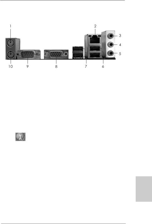
I/O Panel
1 |
PS/2 |
Mouse |
Port (Green) |
6 |
USB 2.0 |
Ports (USB01) |
|
2 |
RJ-45 |
Port |
|
7 |
USB 2.0 |
Ports |
(USB23) |
3 |
Line In (Light Blue) |
8 |
VGA Port |
|
|
||
4 |
Front Speaker (Lime) |
9 |
COM Port |
|
|||
* 5 |
Microphone |
(Pink) |
10 |
PS/2 Keyboard |
Port (Purple) |
||
*To enable Multi-Streaming function, you need to connect a front panel audio cable to the front panel audio header. Please refer to below steps for the software setting of MultiStreaming.
For Windows® XP:
After restarting your computer, you will find “Mixer” tool on your system. Please select “Mixer
ToolBox” |
, click “Enable playback multi-streaming”, and click “ok”. Choose “2CH” or |
“4CH” and then you are allowed to select “Realtek HDA Primary output” to use Rear Speaker and Front Speaker, or select “Realtek HDA Audio 2nd output” to use front panel audio. Then reboot your system.
For Windows® VistaTM:
After restarting your computer, please double-click “Realtek HD Audio Manager” on the system tray. Set “Speaker Configuration” to “Quadraphonic” or “Stereo”. Click “Device advanced settings”, choose “Make front and rear output devices playbacks two different audio streams simultaneously”, and click “ok”. Then reboot your system.
English
3
ASRock N68-S Motherboard
1. Introduction
Thank you for purchasing ASRock N68-S motherboard, a reliable motherboard produced under ASRock’s consistently stringent quality control. It delivers excellent performance with robust design conforming to ASRock’s commitment to quality and endurance.
In this manual, chapter 1 and 2 contain introduction of the motherboard and step-by-step guide to the hardware installation. Chapter 3 and 4 contain the configuration guide to BIOS setup and information of the Support CD.
Because the motherboard specifications and the BIOS software might be updated, the content of this manual will be subject to change without notice. In case any modifications of this manual occur, the updated version will be available on ASRock website without further notice. You may find the latest VGA cards and CPU support lists on ASRock website as well. ASRock website http://www.asrock.com
If you require technical support related to this motherboard, please visit our website for specific information about the model you are using. www.asrock.com/support/index.asp
1.1 Package Contents
One ASRock N68-S Motherboard
(Micro ATX Form Factor: 9.6-in x 7.0-in, 24.4 cm x 17.8 cm) One ASRock N68-S Quick Installation Guide
Two ASRock N68-S Support CD
One 80-conductor Ultra ATA 66/100/133 IDE Ribbon Cable (Optional) One Serial ATA (SATA) Data Cable (Optional)
One Serial ATA (SATA) HDD Power Cable (Optional) One I/O Panel Shield
English
4
ASRock N68-S Motherboard

1.2 Specifications
Platform |
- Micro ATX Form Factor: 9.6-in x 7.0-in, 24.4 cm x 17.8 cm |
CPU |
- Support for Socket AM2+ / AM2 processors: AMD PhenomTM |
|
FX / Phenom / Athlon 64 FX / Athlon 64 X2 Dual-Core / Athlon |
|
X2 Dual-Core / Athlon 64 / Sempron processor |
|
(see CAUTION 1) |
|
- Support for AM3 processors: AMD PhenomTM II X4 / X3 and |
|
Athlon II X4 / X3 / X2 processors |
|
- Supports AMD’s Cool ‘n’ QuietTM Technology |
|
- FSB 1000 MHz (2.0 GT/s) |
|
- Supports Untied Overclocking Technology (see CAUTION 2) |
|
- Supports Hyper-Transport Technology |
Chipset |
- NVIDIA® GeForce 7025 / nForce 630a |
Memory |
- Dual Channel DDR2 Memory Technology (see CAUTION 3) |
|
- 2 x DDR2 DIMM slots |
|
- SupportDDR2 1066/800/667/533 non-ECC, un-buffered memory |
|
(see CAUTION 4) |
|
- Max. capacity of system memory: 8GB (see CAUTION 5) |
Expansion Slot |
- 1 x PCI Express x16 slot |
|
- 1 x PCI Express x1 slot |
|
- 2 x PCI slots |
Graphics |
- Integrated NVIDIA® GeForce 7025 graphics |
|
- DX9.0 VGA, Pixel Shader 3.0 |
|
- Max. shared memory 256MB (see CAUTION 6) |
Audio |
- 5.1 CH Windows® VistaTM Premium Level HD Audio |
|
(ALC662 Audio Codec) |
LAN |
- Realtek PHY RTL8201EL |
|
- Speed: 10/100 Ethernet |
|
- Supports Wake-On-LAN |
Rear Panel I/O |
I/O Panel |
|
- 1 x PS/2 Mouse Port |
|
- 1 x PS/2 Keyboard Port |
|
- 1 x Serial Port: COM1 |
|
- 1 x VGA Port |
|
- 4 x Ready-to-Use USB 2.0 Ports |
|
- 1 x RJ-45 LAN Port with LED (ACT/LINK LED and SPEED LED) |
|
- HD Audio Jack: Line in / Front Speaker / Microphone |
English
5
ASRock N68-S Motherboard

English
6
Connector |
- 4 x Serial ATAII 3.0Gb/s connectors, support RAID (RAID 0, |
|
RAID 1, RAID 0+1, RAID 5, JBOD), NCQ and “Hot Plug” |
|
functions (see CAUTION 7) |
|
- 1 x ATA133 IDE connector (supports 2 x IDE devices) |
|
- 1 x Floppy connector |
|
- 1 x Print port header |
|
- CPU/Chassis FAN connector |
|
- 24 pin ATX power connector |
|
- 4 pin 12V power connector |
|
- CD in header |
|
- Front panel audio header |
|
- 2 x USB 2.0 headers (support 4 USB 2.0 ports) |
|
(see CAUTION 8) |
BIOS Feature |
- 4Mb AMI BIOS |
|
- AMI Legal BIOS |
|
- Supports “Plug and Play” |
|
- ACPI 1.1 Compliance Wake Up Events |
|
- Supports jumperfree |
|
- SMBIOS 2.3.1 Support |
|
- Supports Smart BIOS |
Support CD |
- Drivers, Utilities, AntiVirus Software (Trial Version) |
Unique Feature |
- ASRock OC Tuner (see CAUTION 9) |
|
- Intelligent Energy Saver (see CAUTION 10) |
|
- Instant Boot |
|
- Hybrid Booster: |
|
- CPU Frequency Stepless Control (see CAUTION 11) |
|
- ASRock U-COP (see CAUTION 12) |
|
- Boot Failure Guard (B.F.G.) |
|
- ASRock AM2 Boost: ASRock Patented Technology to boost |
|
memory performance up to 12.5% (see CAUTION 13) |
Hardware |
- CPU Temperature Sensing |
Monitor |
- Chassis Temperature Sensing |
|
- CPU Fan Tachometer |
|
- Chassis Fan Tachometer |
|
- CPU Quiet Fan |
|
- Voltage Monitoring: +12V, +5V, +3.3V, Vcore |
OS |
- Microsoft® Windows® 2000 / XP / XP 64-bit / VistaTM / |
|
VistaTM 64-bit compliant |
Certifications |
- FCC, CE |
* For detailed product information, please visit our website: http://www.asrock.com
ASRock N68-S Motherboard

WARNING
Please realize that there is a certain risk involved with overclocking, including adjusting the setting in the BIOS, applying Untied Overclocking Technology, or using the third-party overclocking tools. Overclocking may affect your system stability, or even cause damage to the components and devices of your system. It should be done at your own risk and expense. We are not responsible for possible damage caused by overclocking.
CAUTION!
1.This motherboard supports CPU up to 95W. Please refer to our website for
CPU support list. ASRock website http://www.asrock.com
2.This motherboard supports Untied Overclocking Technology. Please read “Untied Overclocking Technology” on page 18 for details.
3.This motherboard supports Dual Channel Memory Technology. Before you implement Dual Channel Memory Technology, make sure to read the installation guide of memory modules on page 11 for proper installation.
4.Whether 1066MHz memory speed is supported depends on the AM2+ CPU you adopt. If you want to adopt DDR2 1066 memory module on this motherboard, please refer to the memory support list on our website for the compatible memory modules.
ASRock website http://www.asrock.com
5.Due to the operating system limitation, the actual memory size may be less than 4GB for the reservation for system usage under Windows® XP and Windows® VistaTM. For Windows® XP 64-bit and Windows® VistaTM 64-bit with 64-bit CPU, there is no such limitation.
6.The maximum shared memory size is defined by the chipset vendor and is subject to change. Please check NVIDIA® website for the latest information.
7.Before installing SATAII hard disk to SATAII connector, please read the “SATAII Hard Disk Setup Guide” on page 22 of “User Manual” in the support CD to adjust your SATAII hard disk drive to SATAII mode. You can also connect SATA hard disk to SATAII connector directly.
8.Power Management for USB 2.0 works fine under Microsoft® Windows® VistaTM 64-bit / VistaTM / XP 64-bit / XP SP1 or SP2 / 2000 SP4.
9.It is a user-friendly ASRock overclocking tool which allows you to surveil your system by hardware monitor function and overclock your hardware devices to get the best system performance under Windows® environment. Please visit our website for the operation procedures of ASRock OC Tuner. ASRock website: http://www.asrock.com
English
7
ASRock N68-S Motherboard

10.Featuring an advanced proprietary hardware and software design, Intelligent Energy Saver is a revolutionary technology that delivers unparalleled power savings. The voltage regulator can reduce the number of output phases to improve efficiency when the CPU cores are idle. In other words, it is able to provide exceptional power saving and improve power efficiency without sacrificing computing performance. To use Intelligent Energy Saver function, please enable Cool ‘n’ Quiet option in the BIOS setup in advance. Please visit our website for the operation procedures of Intelligent Energy Saver.
ASRock website: http://www.asrock.com
11.Although this motherboard offers stepless control, it is not recommended to perform over-clocking. Frequencies other than the recommended CPU bus frequencies may cause the instability of the system or damage the CPU.
12.While CPU overheat is detected, the system will automatically shutdown. Before you resume the system, please check if the CPU fan on the motherboard functions properly and unplug the power cord, then plug it back again. To improve heat dissipation, remember to spray thermal grease between the CPU and the heatsink when you install the PC system.
13.This motherboard supports ASRock AM2 Boost overclocking technology. If you enable this function in the BIOS setup, the memory performance will improve up to 12.5%, but the effect still depends on the AM2 CPU you adopt. Enabling this function will overclock the chipset/CPU reference clock. However, we can not guarantee the system stability for all CPU/DRAM configurations. If your system is unstable after AM2 Boost function is enabled, it may not be applicative to your system. You may choose to disable this function for keeping the stability of your system.
English
8
ASRock N68-S Motherboard
2. Installation
This is a Micro ATX form factor (9.6-in x 7.0-in, 24.4 cm x 17.8 cm) motherboard. Before you install the motherboard, study the configuration of your chassis to ensure that the motherboard fits into it.
Pre-installation Precautions
Take note of the following precautions before you install motherboard components or change any motherboard settings.
Before you install or remove any component, ensure that the power is switched off or the power cord is detached from the power supply. Failure to do so may cause severe damage to the motherboard, peripherals, and/or components.
1.Unplug the power cord from the wall socket before touching any component.
2.To avoid damaging the motherboard components due to static electricity, NEVER place your motherboard directly on the carpet or the like. Also remember to use a grounded wrist strap or touch a safety grounded object before you handle components.
3.Hold components by the edges and do not touch the ICs.
4.Whenever you uninstall any component, place it on a grounded antistatic pad or in the bag that comes with the component.
5.When placing screws into the screw holes to secure the motherboard to the chassis, please do not over-tighten the screws! Doing so may damage the motherboard.
English
9
ASRock N68-S Motherboard
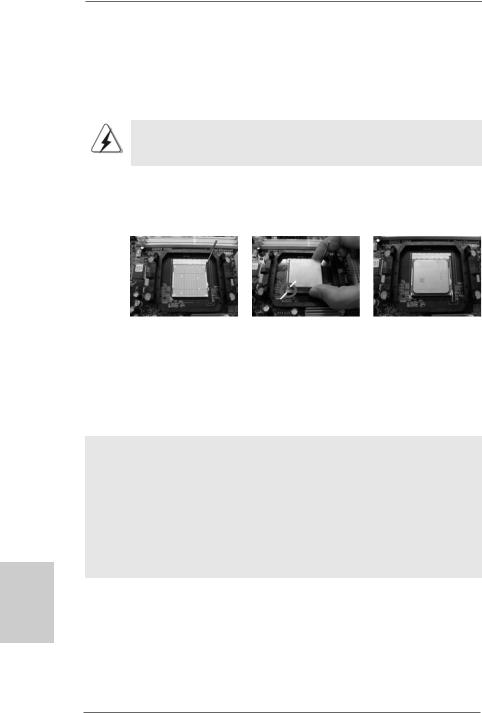
2.1CPU Installation
Step 1. Unlock the socket by lifting the lever up to a 90o angle.
Step 2. Position the CPU directly above the socket such that the CPU corner with the golden triangle matches the socket corner with a small triangle.
Step 3. Carefully insert the CPU into the socket until it fits in place.
The CPU fits only in one correct orientation. DO NOT force the CPU into the socket to avoid bending of the pins.
Step 4. When the CPU is in place, press it firmly on the socket while you push down the socket lever to secure the CPU. The lever clicks on the side tab to indicate that it is locked.
Lever 90°Up |
|
|
|
CPU Golden Triangle |
|
|
Socker Corner Small Triangle |
|
STEP 1: |
STEP 2 / STEP 3: |
STEP 4: |
Lift Up The Socket Lever |
Match The CPU Golden Triangle |
Push Down And Lock |
|
To The Socket Corner Small |
The Socket Lever |
|
Triangle |
|
2.2 Installation of CPU Fan and Heatsink
After you install the CPU into this motherboard, it is necessary to install a larger heatsink and cooling fan to dissipate heat. You also need to spray thermal grease between the CPU and the heatsink to improve heat dissipation. Make sure that the CPU and the heatsink are securely fastened and in good contact with each other. Then connect the CPU fan to the CPU FAN connector (CPU_FAN1, see Page 2, No. 2). For proper installation, please kindly refer to the instruction manuals of the CPU fan and the heatsink.
English
1 0
ASRock N68-S Motherboard
2.3 Installation of Memory Modules (DIMM)
N68-S motherboard provides two 240-pin DDR2 (Double Data Rate 2) DIMM slots, and supports Dual Channel Memory Technology. For dual channel configuration, you always need to install two identical (the same brand, speed, size and chip-type) memory modules in the DDR2 DIMM slots to activate Dual Channel Memory Technology. Otherwise, it will operate at single channel mode.
1.It is not allowed to install a DDR memory module into DDR2 slot; otherwise, this motherboard and DIMM may be damaged.
2.If you install only one memory module or two non-identical memory modules, it is unable to activate the Dual Channel Memory Technology.
Installing a DIMM
Please make sure to disconnect power supply before adding or removing DIMMs or the system components.
Step 1. Unlock a DIMM slot by pressing the retaining clips outward.
Step 2. Align a DIMM on the slot such that the notch on the DIMM matches the break on the slot.
The DIMM only fits in one correct orientation. It will cause permanent damage to the motherboard and the DIMM if you force the DIMM into the slot at incorrect orientation.
Step 3. Firmly insert the DIMM into the slot until the retaining clips at both ends fully snap back in place and the DIMM is properly seated.
1 1
English
ASRock N68-S Motherboard

2.4 Expansion Slots (PCI and PCI Express Slots)
There are 2 PCI slots and 2 PCI Express slots on this motherboard.
PCI slots: PCI slots are used to install expansion cards that have the 32-bit PCI interface.
PCIE slots: PCIE1 (PCIE x1 slot) is used for PCI Express cards with x1 lane width cards, such as Gigabit LAN card, SATA2 card, etc.
PCIE2 (PCIE x16 slot) is used for PCI Express cards with x16 lane width graphics cards.
Installing an expansion card
Step 1. Before installing the expansion card, please make sure that the power supply is switched off or the power cord is unplugged. Please read the documentation of the expansion card and make necessary hardware
settings for the card before you start the installation.
Step 2. Remove the bracket facing the slot that you intend to use. Keep the screws for later use.
Step 3. Align the card connector with the slot and press firmly until the card is completely seated on the slot.
Step 4. Fasten the card to the chassis with screws.
English
1 2
ASRock N68-S Motherboard
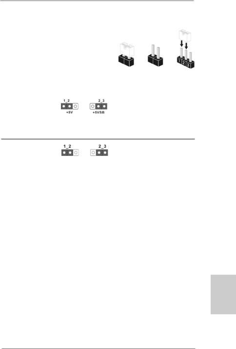
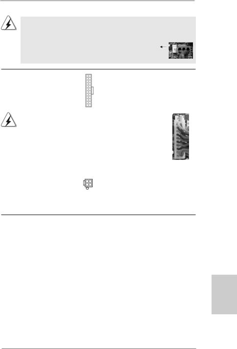
2.5 Jumpers Setup
The illustration shows how jumpers are setup. When the jumper cap is placed on pins, the jumper is “Short”. If no jumper cap is placed on pins, the jumper is “Open”. The illustration shows a 3-pin jumper whose pin1
and pin2 are “Short” when jumper cap is Short Open placed on these 2 pins.
Jumper |
Setting |
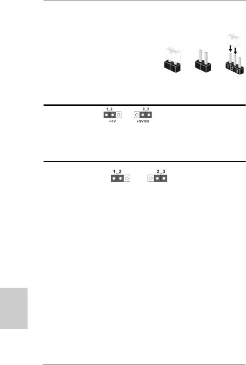
PS2_USB_PW1 |
Short pin2, pin3 to enable |
(see p.2, No. 1) |
+5VSB (standby) for PS/2 or |
|
USB wake up events. |
Note: To select +5VSB, it requires 2 Amp and higher standby current provided by power supply.
Clear CMOS Jumper
(CLRCMOS1)
(see p.2, No. 13) Default Clear CMOS
Note: CLRCMOS1 allows you to clear the data in CMOS. The data in CMOS includes system setup information such as system password, date, time, and system setup parameters. To clear and reset the system parameters to default setup, please turn off the computer and unplug the power cord from the power supply. After waiting for 15 seconds, use a jumper cap to short pin2 and pin3 on CLRCMOS1 for 5 seconds. However, please do not clear the CMOS right after you update the BIOS. If you need to clear the CMOS when you just finish updating the BIOS, you must boot up the system first, and then shut it down before you do the clear-CMOS action.
English
1 3
ASRock N68-S Motherboard
English
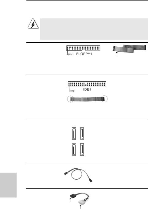
2.6 Onboard Headers and Connectors
Onboard headers and connectors are NOT jumpers. Do NOT place jumper caps over these headers and connectors. Placing jumper caps over the headers and connectors will cause permanent damage of the motherboard!
•
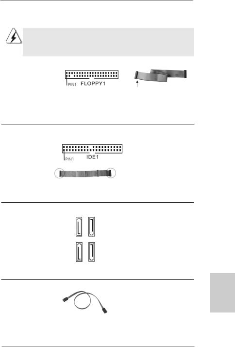
Floppy Connector
(33-pin FLOPPY1)
(see p.2 No. 19)
the red-striped side to Pin1
Note: Make sure the red-striped side of the cable is plugged into Pin1 side of the connector.
Primary IDE connector (Blue)
(39-pin IDE1, see p.2 No. 6)
connect the blue end |
connect the black end |
to the motherboard |
to the IDE devices |
80-conductor ATA 66/100/133 cable
Note: Please refer to the instruction of your IDE device vendor for the details.
Serial ATAII Connectors
(SATAII_1 (PORT 1.0): |
SATAII 1 |
(PORT1.0) |
SATAII2 |
(PORT1.1) |
|
see p.2, No. 9) |
|||||
(SATAII_2 (PORT 1.1): |
|||||
|
|
|
|
||
see p.2, No. 5) |
|
(PORT2.0) |
|
(PORT2.1) |
|
(SATAII_3 (PORT 2.0): |
SATAII3 |
SATAII4 |
|||
(SATAII_4 (PORT 2.1): |
|||||
see p.2, No. 8) |
|
|
|
|
|
see p.2, No. 7) |
|
|
|
|
|
Serial ATA (SATA) |
|
|
|
|
|
Data Cable |
|
|
|
|
(Optional)
Serial ATA (SATA) Power Cable
(Optional)
connect to the SATA
HDD power connector
connect to the powersupply
1 4
These four Serial ATAII (SATAII) connectors support SATAII
or SATA hard disk for internal storage devices. The current SATAII interface allows up to 3.0 Gb/s data transfer rate.
Either end of the SATA data cable can be connected to the SATA /
SATAII hard disk or the SATAII connector on the motherboard.
Please connect the black end of SATA power cable to the power connector on each drive. Then connect the white end of SATA power cable to the power connector of the power supply.
ASRock N68-S Motherboard
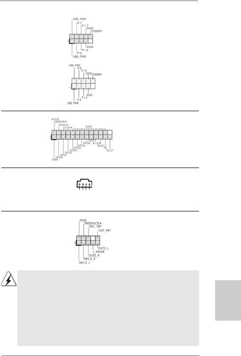
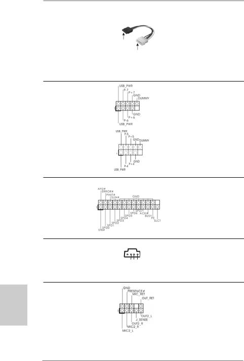
USB 2.0 Headers |
Besides four default USB 2.0 |
(9-pin USB6_7) |
ports on the I/O panel, there are |
(see p.2 No. 16) |
two USB 2.0 headers on this |
|
motherboard. Each USB 2.0 |
|
header can support two USB |
|
2.0 ports. |
(9-pin USB4_5) |
|
(see p.2 No. 14) |
|
Print Port Header
(25-pin LPT1)
(see p.2 No. 18)
Internal Audio Connectors
(4-pin CD1)
(CD1: see p.2 No. 20)
Front Panel Audio Header
(9-pin HD_AUDIO1)
(see p.2, No. 21)
CD1
L-CD
GND
GND
R-CD
This is an interface for print port cable that allows convenient connection of printer devices.
This connector allows you to receive stereo audio input from sound sources such as a CD-ROM, DVD-ROM, TV tuner card, or MPEG card.
This is an interface for the front panel audio cable that allows convenient connection and control of audio devices.
1.High Definition Audio supports Jack Sensing, but the panel wire on the chassis must support HDA to function correctly. Please follow the
instruction in our manual and chassis manual to install your system.
2.If you use AC’97 audio panel, please install it to the front panel audio header as below:
A.Connect Mic_IN (MIC) to MIC2_L.
B.Connect Audio_R (RIN) to OUT2_R and Audio_L (LIN) to OUT2_L.
C.Connect Ground (GND) to Ground (GND).
D.MIC_RET and OUT_RET are for HD audio panel only. You don’t need to connect them for AC’97 audio panel.
English
1 5
ASRock N68-S Motherboard
E.Enter BIOS Setup Utility. Enter Advanced Settings, and then select Chipset Configuration. Set the Front Panel Control option from
[Auto] to [Enabled].
F.Enter Windows system. Click the icon on the lower right hand taskbar to enter Realtek HD Audio Manager.
For Windows® 2000 / XP / XP 64-bit OS:
Click “Audio I/O”, select “Connector Settings”  , choose
“Disable front panel jack detection”, and save the change by clicking “OK”.
For Windows® VistaTM / VistaTM 64-bit OS:
Click the right-top “Folder” icon , choose “Disable front
panel jack detection”, and save the change by clicking “OK”. G. To activate the front mic.
For Windows® 2000 / XP / XP 64-bit OS:
Please select “Front Mic” as default record device.
If you want to hear your voice through front mic, please deselect "Mute" icon in “Front Mic” of “Playback” portion.
For Windows® VistaTM / VistaTM 64-bit OS:
Go to the "Front Mic" Tab in the Realtek Control panel.
Click "Set Default Device" to make the Front Mic as the default record device.
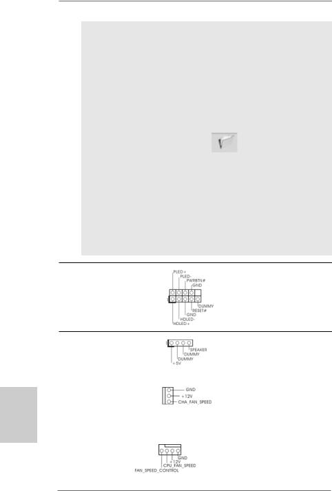
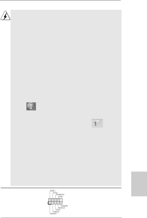
System Panel Header |
This header accommodates |
(9-pin PANEL1) |
several system front panel |
(see p.2 No. 17) |
functions. |
English
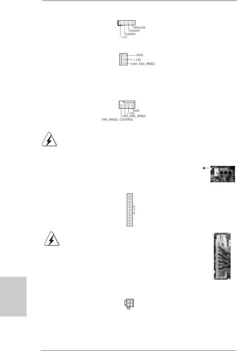
Chassis Speaker Header |
Please connect the chassis |
(4-pin SPEAKER 1) |
speaker to this header. |
(see p.2 No. 15) |
|
|
|
Chassis Fan Connector |
Please connect a chassis fan |
(3-pin CHA_FAN1) |
cable to this connector and |
(see p.2 No. 12) |
match the black wire to the |
|
ground pin. |
|
|
CPU Fan Connector |
Please connect the CPU fan |
|
4 3 2 1 |
(4-pin CPU_FAN1) |
cable to this connector and |
(see p.2 No. 2) |
match the black wire to the |
|
ground pin. |
1 6
ASRock N68-S Motherboard
Though this motherboard provides 4-Pin CPU fan (Quiet Fan) support, the 3-Pin CPU fan still can work successfully even without the fan speed control function. If you plan to connect the 3-Pin CPU fan to the CPU fan connector on this
motherboard, please connect it to Pin 1-3.
Pin 1-3 Connected
3-Pin Fan Installation
ATX Power Connector |
12 |
24 |
Please connect an ATX power |
|
||
(24-pin ATXPWR1) |
|
|
supply to this connector. |
|
||
(see p.2 |
No. 4) |
|
|
|
|
|
|
|
|
1 |
13 |
|
|
|
|
|
|
|||
|
|
Though this motherboard provides 24-pin ATX power connector, 12 |
24 |
|||
|
|
it can still work if you adopt a traditional 20-pin ATX power supply. |
|
|||
|
|
To use the 20-pin ATX power supply, please plug your power |
|
|||
|
|
supply along with Pin 1 and Pin 13. |
|
|
||
|
|
|
|
20-Pin ATX Power Supply Installation |
13 |
|
|
|
|
|
|
1 |
|
|
|
|
|
|
||
|
|
|
|
|
|
|
ATX 12V Power Connector |
|
|
Please note that it is necessary |
|||
(4-pin ATX12V1) |
|
|
to connect a power supply with |
|||
(see p.2 |
No. 25) |
|
|
ATX 12V plug to this connector. |
||
|
|
|
|
|
Failing to do so will cause power |
|
|
|
|
|
|
up failure. |
|
2.7 Driver Installation Guide
To install the drivers to your system, please insert the support CD to your optical drive first. Then, the drivers compatible to your system can be auto-detected and listed on the support CD driver page. Please follow the order from up to bottom side to install those required drivers. Therefore, the drivers you install can work properly.
2.8 Installing Windows® 2000 / XP / XP 64-bit / VistaTM / VistaTM 64-bit Without RAID Functions
If you just want to install Windows® 2000, Windows® XP, Windows® XP 64-bit, Windows® VistaTM or Windows® VistaTM 64-bit on your SATA / SATAII HDDs without RAID functions, you don’t have to make a SATA / SATAII driver diskette. Besides, there is no need for you to change the BIOS setting. You can start to install Windows® 2000, Windows® XP, Windows® XP 64-bit, Windows® VistaTM or Windows® VistaTM 64-bit on your system directly.
1 7
English
ASRock N68-S Motherboard
English
2.9 Installing Windows® 2000 / XP / XP 64-bit / VistaTM / VistaTM 64-bit With RAID Functions
If you want to install Windows® 2000 / XP / XP 64-bit / VistaTM / VistaTM 64-bit on your SATA / SATAII HDDs with RAID functions, please refer to the document at the following path in the Support CD for detailed procedures:
..\ RAID Installation Guide
2.10 Untied Overclocking Technology
This motherboard supports Untied Overclocking Technology, which means during overclocking, FSB enjoys better margin due to fixed PCI / PCIE buses. Before you enable Untied Overclocking function, please enter “Overclock Mode” option of BIOS setup to set the selection from [Auto] to [CPU, PCIE, Async.]. Therefore, CPU FSB is untied during overclocking, but PCI / PCIE buses are in the fixed mode so that FSB can operate under a more stable overclocking environment.
Please refer to the warning on page 7 for the possible overclocking risk before you apply Untied Overclocking Technology.
3. BIOS Information
The Flash Memory on the motherboard stores BIOS Setup Utility. When you start up the computer, please press <F2> during the Power-On-Self-Test (POST) to enter BIOS Setup utility; otherwise, POST continues with its test routines. If you wish to enter BIOS Setup after POST, please restart the system by pressing <Ctl> + <Alt> + <Delete>, or pressing the reset button on the system chassis. The BIOS Setup program is designed to be user-friendly. It is a menu-driven program, which allows you to scroll through its various sub-menus and to select among the predetermined choices. For the detailed information about BIOS Setup, please refer to the User Manual (PDF file) contained in the Support CD.
4. Software Support CD information
This motherboard supports various Microsoft® Windows® operating systems: 2000 /
XP / XP Media Center / XP 64-bit / VistaTM / VistaTM 64-bit. The Support CD that came with the motherboard contains necessary drivers and useful utilities that will enhance motherboard features. To begin using the Support CD, insert the CD into your CD-ROM drive. It will display the Main Menu automatically if “AUTORUN” is enabled in your computer. If the Main Menu does not appear automatically, locate and doubleclick on the file “ASSETUP.EXE” from the “BIN” folder in the Support CD to display the menus.
1 8
ASRock N68-S Motherboard
1. Einführung
Wir danken Ihnen für den Kauf desASRock N68-S Motherboard, ein zuverlässiges Produkt, welches unter den ständigen, strengen Qualitätskontrollen von ASRock gefertigt wurde. Es bietet Ihnen exzellente Leistung und robustes Design, gemäß der Verpflichtung von ASRock zu Qualität und Halbarkeit.
Diese Schnellinstallationsanleitung führt in das Motherboard und die schrittweise Installation ein. Details über das Motherboard finden Sie in der Bedienungsanleitung auf der Support-CD.
Da sich Motherboard-Spezifikationen und BIOS-Software verändern können, kann der Inhalt dieses Handbuches ebenfalls jederzeit geändert werden. Für den Fall, dass sich Änderungen an diesem Handbuch ergeben, wird eine neue Version auf der ASRock-Website, ohne weitere Ankündigung, verfügbar sein. Die neuesten Grafikkarten und unterstützten CPUs sind auch auf der ASRock-Website aufgelistet.
ASRock-Website: http://www.asrock.com
Wenn Sie technische Unterstützung zu Ihrem Motherboard oder spezifische Informationen zu Ihrem Modell benötigen, besuchen Sie bitte unsere Webseite:
www.asrock.com/support/index.asp
1.1 Kartoninhalt
ASRock N68-S Motherboard
(Micro ATX-Formfaktor: 24.4 cm x 17.8 cm; 9.6 Zoll x 7.0 Zoll)
ASRock N68-S Schnellinstallationsanleitung
ASRock N68-S Support-CD
Ein 80-adriges Ultra-ATA 66/100/133 IDE-Flachbandkabel (Option)
Ein Seriell-ATA- (SATA) Datenkabel (Option)
Ein Seriell-ATA (SATA) Festplattennetzkabel (Option)
Ein I/O Shield
Deutsch
1 9
ASRock N68-S Motherboard

1.2 Spezifikationen
Deutsch
2 0
Plattform |
- Micro ATX-Formfaktor: 24.4 cm x 17.8 cm; 9.6 Zoll x 7.0 Zoll |
CPU |
- Unterstützung für Socket AM2+ / AM2-Prozessoren: AMD |
|
PhenomTM FX / Phenom / Athlon 64 FX / Athlon 64 X2 Dualkern |
|
/ Athlon X2 Dualkern / Athlon 64 / Sempron-Prozessor |
|
(siehe VORSICHT 1) |
|
- Unterstützung von AM3-Prozessoren: AMD PhenomTM II X4 / X3 |
|
und Athlon X4 / X3 / X2-Prozessor |
|
- Unterstützt Cool ‘n’ QuietTM-Technologie von AMD |
|
- FSB 1000 MHz (2.0 GT/s) |
|
- Unterstützt Untied-Übertaktungstechnologie |
|
(siehe VORSICHT 2) |
|
- Unterstützt Hyper-Transport-Technologie |
Chipsatz |
- NVIDIA® GeForce 7025 / nForce 630a |
Speicher |
- Unterstützung von Dual-Kanal-Speichertechnologie |
|
(siehe VORSICHT 3) |
|
- 2 x Steckplätze für DDR2 |
|
- Unterstützt DDR2 1066/800/667/533 non-ECC, ungepufferter |
|
Speicher (siehe VORSICHT 4) |
|
- Max. Kapazität des Systemspeichers: 8GB |
|
(siehe VORSICHT 5) |
Erweiterungs- |
- 1 x PCI Express x16-Steckplätze |
steckplätze |
- 1 x PCI Express x1-Steckplätze |
|
- 2 x PCI -Steckplätze |
Onboard-VGA |
- Integrierter NVIDIA® GeForce 7025 Grafikchip |
|
- DX9.0 VGA, Pixel Shader 3.0 |
|
- Maximal gemeinsam genutzter Speicher 256 MB |
|
(siehe VORSICHT 6) |
Audio |
- 5.1 CH Windows® VistaTM Premium Level HD Audio |
|
(ALC662 Audio Codec) |
LAN |
- Realtek PHY RTL8201EL |
|
- Speed: 10/100 Ethernet |
|
- Unterstützt Wake-On-LAN |
|
|
E/A-Anschlüsse |
I/O Panel |
an der |
- 1 x PS/2-Mausanschluss |
Rückseite |
- 1 x PS/2-Tastaturanschluss |
|
- 1 x Serieller port: COM1 |
|
- 1 x VGA port |
|
- 4 x Standard-USB 2.0-Anschlüsse |
|
- 1 x RJ-45 LAN Port mit LED (ACT/LINK LED und SPEED LED) |
ASRock N68-S Motherboard
|
- HDAudiobuchse: Audioeingang / Lautsprecher vorne / Mikrofon |
Anschlüsse |
- 4 x SATAII-Anschlüsse, unterstützt bis 3.0 Gb/s |
|
Datenübertragungsrate, unterstützt RAID (RAID 0, RAID 1, |
|
RAID 0+1, RAID 5, JBOD), NCQ und “Hot Plug” Funktionen |
|
(siehe VORSICHT 7) |
|
- 1 x ATA133 IDE-Anschlüsse (Unterstützt bis 2 IDE-Geräte) |
|
- 1 x FDD-Anschlüsse |
|
- 1 x Druckerport-Anschlussleiste |
|
- CPU/Gehäuse-Lüfteranschluss |
|
- 24-pinATX-Netz-Header |
|
- 4-pin anschluss für 12V-ATX-Netzteil |
|
- Interne Audio-Anschlüsse |
|
- Anschluss für Audio auf der Gehäusevorderseite |
|
- 2 x USB 2.0-Anschlüsse (Unterstützung 4 zusätzlicher |
|
USB 2.0-Anschlüsse) (siehe VORSICHT 8) |
BIOS |
- 4Mb AMI BIOS |
|
- AMI legal BIOS mit Unterstützung für “Plug and Play” |
|
- ACPI 1.1-Weckfunktionen |
|
- JumperFree-Modus |
|
- SMBIOS 2.3.1 |
|
- Unterstützt Smart BIOS |
Support-CD |
- Treiber, Dienstprogramme, Antivirussoftware |
|
(Probeversion) |
Einzigartige |
- ASRock OC Tuner (siehe VORSICHT 9) |
Eigenschaft |
- Intelligent Energy Saver (Intelligente Energiesparfunktion) |
|
(siehe VORSICHT 10) |
|
- Sofortstart |
|
- Hybrid Booster: |
|
- Schrittloser CPU-Frequenz-Kontrolle |
|
(siehe VORSICHT 11) |
|
- ASRock U-COP (siehe VORSICHT 12) |
|
- Boot Failure Guard (B.F.G. – Systemstartfehlerschutz) |
|
- ASRock AM2 Boost: ASRocks patentgeschützte |
|
Technologie zur Erhöhung der Arbeitsspeicherleistung um |
|
bis zu 12,5% (siehe VORSICHT 13) |
Hardware Monitor |
- CPU-Temperatursensor |
|
- Motherboardtemperaturerkennung |
|
- Drehzahlmessung für CPU-Lüfter |
|
- Drehzahlmessung für Gehäuselüfter |
|
- CPU-Lüftergeräuschdämpfung |
|
- Spannungsüberwachung: +12V, +5V, +3.3V, Vcore |
|
|
Deutsch
2 1
ASRock N68-S Motherboard

Deutsch
Betriebssysteme |
- Unterstützt Microsoft® Windows® 2000 / XP / XP Media |
|
Center / XP 64-Bit / VistaTM / VistaTM 64-Bit |
Zertifizierungen |
- FCC, CE |
*Für die ausführliche Produktinformation, besuchen Sie bitte unsere Website: http://www.asrock.com
WARNUNG
Beachten Sie bitte, dass Overclocking, einschließlich der Einstellung im BIOS, Anwenden der Untied Overclocking-Technologie oder Verwenden von Overclocking-Werkzeugen von Dritten, mit einem gewissen Risiko behaftet ist. Overclocking kann sich nachteilig auf die Stabilität Ihres Systems auswirken oder sogar Komponenten und Geräte Ihres Systems beschädigen. Es geschieht dann auf eigene Gefahr und auf Ihre Kosten. Wir übernehmen keine Verantwortung für mögliche Schäden, die aufgrund von Overclocking verursacht wurden.
VORSICHT!
1.Dieses Motherboard unterstützt CPUs bis 95W. Auf unserer Website finden Sie eine Liste mit unterstützten CPUs.
ASRock-Internetseite: http://www.asrock.com
2.Dieses Motherboard unterstützt die Untied-Übertaktungstechnologie. Unter “Entkoppelte Übertaktungstechnologie” auf Seite 18 finden Sie detaillierte Informationen.
3.Dieses Motherboard unterstützt Dual-Kanal-Speichertechnologie. Vor Implementierung der Dual-Kanal-Speichertechnologie müssen Sie die Installationsanleitung für die Speichermodule auf Seite 11 zwecks richtigerInstallation gelesen haben.
4.Ob die Speichergeschwindigkeit 1066 MHz unterstützt wird, hängt von der von Ihnen eingesetzten AM2+-CPU ab. Schauen Sie bitte auf unseren Internetseiten in der Liste mit unterstützten Speichermodulen nach, wenn Sie DDR2 1066-Speichermodule einsetzen möchten.
ASRock-Internetseite: http://www.asrock.com
5.Durch Betriebssystem-Einschränkungen kann die tatsächliche Speichergröße weniger als 4 GB betragen, da unter Windows® XP und Windows® Vista™ etwas Speicher zur Nutzung durch das System reserviert wird. Unter Windows® XP 64-bit und Windows® Vista™ 64-bit mit 64-Bit-CPU besteht diese Einschränkung nicht.
6.Die Maximalspeichergröße ist von den Chipshändler definiert und umgetauscht. Bitte überprüfen Sie NVIDIA® website für die neuliche Information.
7.Vor Installation der SATAII-Festplatte an den SATAII-Anschluss lesen Sie bitte “Setup-Anleitung für SATAII-Festplatte” auf Seite 22 der “Bedienungsanleitung” auf der Support-CD, um Ihre SATAII-Festplatte dem SATAII-Modus anzugleichen. Sie können die SATA-Festplatte auch direkt mit dem SATAII-Anschluss verbinden.
8.Das Power Management für USB 2.0 arbeitet unter Microsoft® Windows® VistaTM 64-Bit / VistaTM / XP 64-Bit / XP SP1 oder SP2/2000 SP4 einwandfrei.
2 2
ASRock N68-S Motherboard

9.Es ist ein benutzerfreundlicher ASRock Übertaktenswerkzeug, das erlaubt, dass Sie Ihr System durch den Hardware-Monitor Funktion zu überblicken und Ihre Hardware-Geräte übertakten, um die beste Systemleistung unter der Windows® Umgebung zu erreichen. Besuchen Sie bitte unsere Website für die Operationsverfahren von ASRock OC Tuner. ASRock-Website: http://www.asrock.com
10.Mit einer eigenen, modernen Hardware und speziellem Softwaredesign, bietet der Intelligent Energy Saver eine revolutionäre Technologie zur bisher unerreichten Energieeinsparung. Ein Spannungsregler kann die Anzahl von Ausgangsphasen zur Effektivitätsverbessserung reduzieren, wenn sich die CPU im Leerlauf befindet. Mit anderen Worten: Sie genießen außergewöhnliche Energieeinsparung und verbesserten Wirkungsgrad ohne Leistungseinschränkungen. Wenn Sie die Intelligent Energy Saver-Funktion nutzen möchten, aktivieren Sie zuvor die „Cool ‘n’ Quiet“-Option im BIOS. Weitere Bedienungshinweise zum Intelligent Energy Saver finden Sie auf unseren Internetseiten. ASRock-Internetseite: http://www.asrock.com
11.Obwohl dieses Motherboard stufenlose Steuerung bietet, wird Overclocking nicht empfohlen. Frequenzen, die von den empfohlenen CPU-Busfrequenzen abweichen, können Instabilität des Systems verursachen oder die CPU beschädigen.
12.Wird eine Überhitzung der CPU registriert, führt das System einen automatischen Shutdown durch. Bevor Sie das System neu starten, prüfen Sie bitte, ob der CPU-Lüfter am Motherboard richtig funktioniert, und stecken Sie bitte den Stromkabelstecker aus und dann wieder ein. Um die Wärmeableitung zu verbessern, bitte nicht vergessen, etwas Wärmeleitpaste zwischen CPU und Kühlkörper zu sprühen.
13.Dieses Motherboard unterstützt die ASRock AM2 Boost Übertaktungstechnologie. Wenn Sie diese Funktion im BIOS-Setup aktivieren, wird die Arbeitsspeicherleistung um bis zu 12,5% gesteigert. Die Wirkung hängt aber von der verwendeten AM2 CPU ab. Diese Funktion übertaktet die Standardfrequenz des Chipsatz und der CPU. Dennoch gewähren wir die Systemstabilität nicht bei allen CPU/DRAMKonfigurationen. Wird Ihr System nach dem Aktivieren der AM2 BoostFunktion unstabil, dann ist diese Funktion wahrscheinlich nicht für Ihr System geeignet. Sie können diese Funktion deaktivieren, um die Stabilität Ihres System zu bewahren.
Deutsch
2 3
ASRock N68-S Motherboard
Deutsch
1.3 Einstellung der Jumper
DieAbbildung verdeutlicht, wie Jumper gesetzt werden. Werden Pins durch Jumperkappen verdeckt, ist der Jumper “gebrückt”. Werden keine Pins durch Jumperkappen verdeckt, ist der Jumper “offen”. Die Abbildung zeigt einen
3-Pin Jumper dessen Pin1 und Pin2 “gebrückt”
sind, bzw. es befindet sich eine Jumper-Kappe Gebrückt Offen auf diesen beiden Pins.
Einstellun
Überbrücken Sie Pin2, Pin3, um
+5VSB (Standby) zu setzen und die PS/2 oder USBWeckfunktionen zu aktivieren.
Um +5VSB nutzen zu können, muss das Netzteil auf dieser Leitung 2A oder mehr leisten können.
CMOS löschen
(CLRCMOS1, 3-Pin jumper) (siehe S.2, No. 13)
DefaultCMOS Einstellung löschen
Hinweis: CLRCMOS1 erlaubt Ihnen das Löschen der CMOS-Daten. Diese beinhalten das System-Passwort, Datum, Zeit und die verschiedenen BIOS-Parameter. Um die Systemparameter zu löschen und auf die Werkseinstellung zurückzusetzen, schalten Sie bitte den Computer ab und entfernen das Stromkabel. Benutzen Sie eine Jumperkappe, um die Pin 2 und Pin 3 an CLRCMOS1 für 5 Sekunden kurzzuschließen. Bitte vergessen Sie nicht, den Jumper wieder zu entfernen, nachdem das CMOS gelöscht wurde. Bitte vergessen Sie nicht, den Jumper wieder zu entfernen, nachdem das CMOS gelöscht wurde. Wenn Sie den CMOSInhalt gleich nach dem Aktualisieren des BIOS löschen müssen, müssen Sie zuerst das System starten und dann wieder ausschalten, bevor Sie den CMOS-Inhalt löschen.
2 4
ASRock N68-S Motherboard
1.4 Anschlüsse
Anschlussleisten sind KEINE Jumper. Setzen Sie KEINE Jumperkappen auf die Pins der Anschlussleisten. Wenn Sie die Jumperkappen auf die Anschlüsse setzen, wird das Motherboard permanent beschädigt!
Anschluss |
Beschreibung |
|
Anschluss für das |
|
|
Floppy-Laufwerk |
|
|
(33-Pin FLOPPY1) |
die rotgestreifte Seite auf Stift 1 |
|
(siehe S.2, No. 19) |
||
|
Hinweis: Achten Sie darauf, dass die rotgestreifte Seite des Kabel mit der Stift 1-
Seite des Anschlusses verbunden wird.
Primärer IDE-Anschluss (blau)
(39-pin IDE1, siehe S.2, No. 6)
Blauer Anschluss |
Schwarzer Anschluss |
zum Motherboard |
zur Festplatte |
|
80-adriges ATA 66/100/133 Kabel |
Hinweis: Details entnehmen Sie bitte den Anweisungen Ihres IDE-Gerätehändlers.
Seriell-ATAII-Anschlüsse
(SATAII_1 (PORT 1.0): siehe S.2, No. 9) (SATAII_2 (PORT 1.1): siehe S.2, No. 5) (SATAII_3 (PORT 2.0): siehe S.2, No. 8) (SATAII_4 (PORT 2.1): siehe S.2, No. 7)
SATAII 1 |
(PORT 1.0) |
SATAII 2 |
(PORT 1.1) |
SATAII 3 |
(PORT 2.0) |
SATAII 4 |
(PORT 2.1) |
Diese vier Serial ATA (SATA II) -Anschlüsse unterstützen interne SATAoder SATA II-Festplatten. Die aktuelle SATAII-Schnittstelle ermöglicht eine Datenübertragungsrate bis 3,0 Gb/s.
Serial ATA- (SATA-) |
Sie können beide Enden des |
Datenkabel |
SATA-Datenkabels entweder |
(Option) |
mit der SATA / SATAII- |
|
Festplatte oder |
|
dem SATAII-Anschluss am |
|
Mainboard verbinden. |
2 5
Deutsch
ASRock N68-S Motherboard
Serial ATA- (SATA-)
Stromversorgungskabel
(Option)
Verbindung zum
SATA-HDD-Stromanschluss
Verbindung zum Netzteil
Verbinden Sie das schwarze Ende des SATA-Netzkabels mit dem Netzanschluss am Laufwerk. Verbinden Sie dann das weiße Ende des SATAStromversorgungskabels mit dem Stromanschluss des Netzteils.
USB 2.0-Header |
Zusätzlich zu den vier |
(9-pol. USB6_7) |
üblichen USB 2.0-Ports an den |
(siehe S.2 - No. 16) |
I/O-Anschlüssen befinden sich |
|
zwei USB 2.0-Anschlussleisten |
|
am Motherboard. Pro USB 2.0- |
|
Anschlussleiste werden zwei |
(9-pol. USB4_5) |
USB 2.0-Ports unterstützt. |
(siehe S.2 - No. 14) |
|
Deutsch
Druckerport-Anschlussleiste
(25-pol. LPT1)
(siehe S.2 - No. 18)
Interne Audio-Anschlüsse
(4-Pin CD1)
(CD1: siehe S.2 - No. 20)
Anschluss für Audio auf der Gehäusevorderseite
(9-Pin HD_AUDIO1)
(siehe S.2, No. 21)
2 6
Dies ist eine Schnittstelle zum Anschluss eines DruckerportKabels, mit dem Sie passende Drucker auf einfache Weise anschließen können.
|
|
|
|
Diese ermöglichen Ihnen |
|
|
|
CD1 |
Stereo-Signalquellen, wie z. B. |
|
|
|
CD-ROM,DVD-ROM, TV-Tuner |
|
R-CD |
L-CD GND GND |
|
||
|
oder MPEG-Karten mit Ihrem |
|||
|
|
|
|
|
|
|
|
|
System zu verbinden. |
Dieses Interface zu einem
Audio-Panel auf der Vorderseite
Ihres Gehäuses, ermöglicht
Ihnen eine bequeme
Kontrolle über Audio-Geräte.
ASRock N68-S Motherboard
1.High Definition Audio unterstützt Jack Sensing (automatische Erkennung falsch angeschlossener Geräte), wobei jedoch die Bildschirmverdrahtung am Gehäuse HDA unterstützen muss, um richtig zu funktionieren.
Beachten Sie bei der Installation im System die Anweisungen in unserem Handbuch und im Gehäusehandbuch.
2.Wenn Sie die AC’97-Audioleiste verwenden, installieren Sie diese wie nachstehend beschrieben an der Front-Audioanschlussleiste:
A.Schließen Sie Mic_IN (MIC) an MIC2_L an.
B.Schließen Sie Audio_R (RIN) an OUT2_R und Audio_L (LIN) an OUT2_L an.
C.Schließen Sie Ground (GND) an Ground (GND) an.
D.MIC_RET und OUT_RET sind nur für den HD-Audioanschluss gedacht. Diese Anschlüsse müssen nicht an die AC’97-Audioleiste angeschlossen werden.
E.Rufen Sie das BIOS-Setup-Dienstprogramm auf. Wechseln Sie zu Erweiterte Einstellungen und wählen Sie Chipset-Konfiguration. Setzen
Sie die Option Frontleistenkontrolle von [Automatisch] auf [Aktiviert].
F.Rufen Sie das Windows-System auf. Klicken Sie auf das Symbol in der Taskleiste unten rechts, um den Realtek HD Audio-Manager aufzurufen. Für Windows® 2000 / XP / XP 64-Bit Betriebssystem:
Klicken Sie auf “Audio-E/A”, wählen Sie die “Anschlusseinstellungen”
, wählen Sie “Erkennung der Frontleistenbuchse
deaktivieren” und speichern Sie die Änderung durch Klicken auf “OK”.
Für Windows® VistaTM / VistaTM 64-Bit Betriebssystem: |
|
Die Rechtoberseite „Dateiordner“ Ikone anklicken |
, |
„Schalttafel Buchse Entdeckung sperren“ wählen und die Änderung speichern, indem Sie „OKAY“ klicken.
G. Aktivierung des vorderseitigen Mikrofons.
Für Betriebssystem Windows® 2000 / XP / XP 64-Bit:
Wählen Sie “Front Mic” (Vorderes Mikr.) als Standard-Aufnahmegerät. Möchten Sie Ihre Stimme über das vorderseitige Mikrofon hören, dann wählen Sie bitte das Symbol “Mute” (Stumm) unter “Front Mic” (Vorderes Mikr.) im Abschnitt “Playback” (Wiedergabe) ab.
Für Betriebssystem Windows® VistaTM / VistaTM 64-Bit:
Rufen Sie die Registerkarte “Front Mic” (Vorderes Mikr.) im RealtekBedienfeld auf. Klicken Sie auf “Set Default Device” (Standardgerät einstellen), um das vorderseitige Mikrofon als StandardAufnahmegerät zu übernehmen.
System Panel Anschluss |
Dieser Anschluss ist für die |
(9-Pin PANEL1) |
verschiedenen Funktionen der |
(siehe S.2, No. 17) |
Gehäusefront. |
2 7
Deutsch
ASRock N68-S Motherboard
Gehäuselautsprecher-Header |
Schließen Sie den |
|
(4-pin SPEAKER1) |
Gehäuselautsprecher an |
|
(siehe S.2, No. 15) |
diesen Header an. |
|
|
|
|
Gehäuse-Lüfteranschluss |
Verbinden Sie das |
|
(3-pin CHA_FAN1) |
Gehäuselüfterkabel mit diesem |
|
(siehe S.2, No. 12) |
Anschluss und passen Sie den |
|
|
|
schwarzen Draht dem |
|
|
Erdungsstift an. |
|
|
|
CPU-Lüfteranschluss |
Verbinden Sie das CPU - |
|
|
|
4 3 2 1 |
(4-pin CPU_FAN1) |
Lüfterkabel mit diesem |
|
(siehe S.2, No. 2) |
Anschluss und passen Sie den |
|
|
|
schwarzen Draht dem |
|
|
Erdungsstift an. |
|
|
|
|
|
|
|
|
|
Deutsch
ATX-Netz-Header |
12 |
24 |
Verbinden Sie die ATX- |
|
||
|
|
|
||||
(24-pin ATXPWR1) |
|
|
Stromversorgung mit diesem |
|
||
(siehe S.2, No. 4) |
|
|
Header. |
|
|
|
|
|
1 |
13 |
|
|
|
|
|
|
|
|||
|
Obwohl dieses Motherboard einen 24-pol. ATX-Stromanschluss |
12 |
24 |
|||
|
bietet, kann es auch mit einem modifizierten traditionellen 20-pol. |
|
||||
|
ATX-Netzteil verwendet werden. Um ein 20-pol. ATX-Netzteil zu |
|
|
|||
|
verwenden, stecken Sie den Stecker mit Pin 1 und Pin 13 ein. |
|
|
|||
|
|
|
Installation eines 20-pol. ATX-Netzteils |
1 |
13 |
|
|
|
|
|
|
||
|
|
|
|
|||
Anschluss für |
|
|
Beachten Sie bitte, dass Sie eine |
|||
12V-ATX-Netzteil |
|
|
Stromversorgung mit ATX 12- |
|
||
(4-pin ATX12V1) |
|
|
Volt-Stecker mit diesem |
|
||
(siehe S.2, No. 25) |
|
|
Anschluss verbinden müssen, |
|
||
|
|
|
|
damit ausreichend Strom |
|
|
|
|
|
|
geliefert werden kann. |
|
|
|
|
|
|
Andernfalls reicht der Strom |
|
|
nicht aus, das System zu starten.
2 8
ASRock N68-S Motherboard

2. BIOS-Information
Das Flash Memory dieses Motherboards speichert das Setup-Utility. Drücken Sie <F2> während des POST (Power-On-Self-Test) um ins Setup zu gelangen, ansonsten werden die Testroutinen weiter abgearbeitet. Wenn Sie ins Setup gelangen wollen, nachdem der POST durchgeführt wurde, müssen Sie das System über die Tastenkombination <Ctrl> + <Alt> + <Delete> oder den Reset-Knopf auf der Gehäusevorderseite, neu starten. Natürlich können Sie einen Neustart auch durchführen, indem Sie das System kurz abund danach wieder anschalten.
Das Setup-Programm ist für eine bequeme Bedienung entwickelt worden. Es ist ein menügesteuertes Programm, in dem Sie durch unterschiedliche Untermenüs scrollen und die vorab festgelegten Optionen auswählen können. Für detaillierte
Informationen zum BIOS-Setup, siehe bitte das Benutzerhandbuch (PDF Datei) auf der Support CD.
3. Software Support CD information
Dieses Motherboard unterstützt eine Reiche von Microsoft® Windows®
Betriebssystemen: 2000 / XP / XP Media Center / XP 64-Bit / VistaTM / VistaTM 64-
Bit. Die Ihrem Motherboard beigefügte Support-CD enthält hilfreiche Software,
eren |
|
Treiber und Hilfsprogramme, mit denen Sie die Funktionen Ihres Motherboards |
|
|
|
|
|
verbessern können Legen Sie die Support-CD zunächst in Ihr CD-ROM-Laufwerk |
|
|
ein. Der Willkommensbildschirm mit den Installationsmenüs der CD wird |
|
|
automatisch aufgerufen, wenn Sie die “Autorun”-Funktion Ihres Systems aktiviert |
|
|
haben. Erscheint der Wilkommensbildschirm nicht, so “doppelklicken” Sie bitte auf |
|
|
das File ASSETUP.EXE im BIN-Verzeichnis der Support-CD, um die Menüs |
|
|
aufzurufen. Das Setup-Programm soll es Ihnen so leicht wie möglich machen. Es |
12 |
24 |
ist menügesteuert, d.h. Sie können in den verschiedenen Untermenüs Ihre |
|
|
Auswahl treffen und die Programme werden dann automatisch installiert. |
s |
1 |
13 |
Deutsch
2 9
ASRock N68-S Motherboard
1. Introduction
Merci pour votre achat d’une carte mère ASRock N68-S, une carte mère très fiable produite selon les critères de qualité rigoureux de ASRock. Elle offre des performances excellentes et une conception robuste conformément à l’engagement d’ASRock sur la qualité et la fiabilité au long terme.
Ce Guide d’installation rapide présente la carte mère et constitue un guide d’installation pas à pas. Des informations plus détaillées concernant la carte mère pourront être trouvées dans le manuel l’utilisateur qui se trouve sur le CD d’assistance.
Les spécifications de la carte mère et le BIOS ayant pu être mis à jour, le contenu de ce manuel est sujet à des changements sans notification. Au cas où n’importe qu’elle modification intervenait sur ce manuel, la version mise à jour serait disponible sur le site web ASRock sans nouvel avis. Vous trouverez les listes de prise en charge des cartes VGA et CPU également sur le site Web ASRock. Site web ASRock, http://www.asrock.com
Si vous avez besoin de support technique en relation avec cette carte mère, veuillez consulter notre site Web pour de plus amples informations particulières au modèle que vous utilisez. www.asrock.com/support/index.asp
1.1 Contenu du paquet
Carte mère ASRock N68-S
(Facteur de forme Micro ATX: 9.6 pouces x 7.0 pouces, 24.4 cm x 17.8 cm) Guide d’installation rapide ASRock N68-S
CD de soutien ASRock N68-S
Un câble ruban IDE Ultra ATA 66/100/133 80 conducteurs (Optionnelle) Un câble de données Serial ATA (SATA) (Optionnelle)
Un cordon d’alimentation DD série ATA (SATA) (Optionnelle) Un écran I/O
rançaisF
3 0
ASRock N68-S Motherboard
 Loading...