


H61 Pro BTC

1
ASRock H61 Pro BTC Motherboard
Version 1.0
Published September 2013
Copyright©2013 ASRock INC. All rights reserved.
Copyright Notice:
No part of this documentation may be reproduced, transcribed, transmitted, or
translated in any language, in any form or by any means, except duplication of
documentation by the purchaser for backup purpose, without written consent of
ASRock Inc.
Products and corporate names appearing in this documentation may or may not
be registered trademarks or copyrights of their respective companies, and are used
only for identication or explanation and to the owners’ benet, without intent to
infringe.
Disclaimer:
Specications and information contained in this documentation are furnished for
informational use only and subject to change without notice, and should not be
constructed as a commitment by ASRock. ASRock assumes no responsibility for
any errors or omissions that may appear in this documentation.
With respect to the contents of this documentation, ASRock does not provide
warranty of any kind, either expressed or implied, including but not limited to
the implied warranties or conditions of merchantability or tness for a particular
purpose.
In no event shall ASRock, its directors, ocers, employees, or agents be liable for
any indirect, special, incidental, or consequential damages (including damages for
loss of prots, loss of business, loss of data, interruption of business and the like),
even if ASRock has been advised of the possibility of such damages arising from any
defect or error in the documentation or product.
e terms HDMI™ and HDMI High-Denition Multimedia Interface, and the HDMI
logo are trademarks or registered trademarks of HDMI Licensing LLC in the United
States and other countries.
is device complies with Part 15 of the FCC Rules. Operation is subject to the following
two conditions:
(1) this device may not cause harmful interference, and
(2) this device must accept any interference received, including interference that
may cause undesired operation.
CALIFORNIA, USA ONLY
e Lithium battery adopted on this motherboard contains Perchlorate, a toxic substance
controlled in Perchlorate Best Management Practices (BMP) regulations passed by the
California Legislature. When you discard the Lithium battery in California, USA, please
follow the related regulations in advance.
“Perchlorate Material-special handling may apply, see
www.dtsc.ca.gov/hazardouswaste/perchlorate”
ASRock Website: http://www.asrock.com
English

2
ASRock H61 Pro BTC Motherboard
English
Motherboard Layout
1 1155-Pin CPU Socket 15 SATA2 Connector (SATA2_1)
2 CPU Fan Connector (CPU_FAN1) 16 System Panel Header (PANEL1)
3 ATX 12V Power Connector (ATX12V1) 17 USB 2.0 Header (USB8_9)
4 2 x 240-pin DDR3 DIMM Slots 18 USB 2.0 Header (USB6_7)
(Dual Channel: DDR3_A1, DDR3_B1) 19 COM Port Header (COM1)
5 ATX Power Connector (ATXPWR1) 20 Front Panel Audio Header (HD_AUDIO1)
6 Chassis Fan Connector (CHA_FAN1) 21 PCI Express 2.0 x1 Slot (PCIE6)
7 32Mb SPI Flash 22 PCI Express 2.0 x1 Slot (PCIE5)
8 Intel H61 Chipset 23 PCI Express 2.0 x1 Slot (PCIE4)
9 Clear CMOS Jumper (CLRCMOS1) 24 PCI Express 2.0 x1 Slot (PCIE3)
10 Chassis Speaker Header (SPEAKER1) 25 PCI Express 3.0 x16 Slot (PCIE2)
11 SATA2 Connector (SATA2_2) 26 PCI Express 2.0 x1 Slot (PCIE1)
12 SATA2 Connector (SATA2_0) 27 SLI/XFire Power Connector (SLI/XFIRE_PWR2)
13 Infrared Module Header (IR1) 28 Power Fan Connector (PWR_FAN1)
14 SATA2 Connector (SATA2_3) 29 SLI/XFire Power Connector (SLI/XFIRE_PWR1)
ATXP WR 1
Intel
H61
CMO S
Bat te ry
32Mb
BIOS
DDR 3_ A1 (6 4 b it , 240 -pi n mod ul e)
DDR 3_ B1 (6 4 b it , 240 -pi n mod ul e)
Supe r
I/O
LAN
PHY
AUDIO
CODEC
1
HD_AUD IO1
COM1
1
USB6_7
1
USB8_9
1
1
SPEAKER1
HDLED RESET
PLED PWRBT N
PANEL1
1
CLRCMO S1
1
SATA2_1
SATA2_3
SATA2_0
SATA2_2
PC I E2
PC I E1
PC I E3
PC I E4
PC I E5
PC I E6
RoH S
H6 1 Pr o BT C
ATX12V1
IR1
1
PS2
Keyb oard
PS2
Mous e
VGA 1
Top:
RJ-4 5
USB 2.0
T: USB 4
B: U SB5
USB 2. 0
T:U SB0
B: USB 1
Top:
LINE IN
Center :
FRONT
Bottom :
MIC IN
USB 2. 0
T:U SB2
B: USB 3
HDM I1
CPU_FAN1
CHA_FAN1
PWR_FAN1
1
2
3
4
5
6
7
8
9
10
11
12
14
13
15
16
17
18
1920
21
22
23
24
25
26
28
SLI/XFI RE_PWR 1
X
Fast USB
X
Fast RAM
X
Fast LAN
SLI/XFI RE_PWR 2
27
29

3
ASRock H61 Pro BTC Motherboard
English
I/O Panel
* There are two LED next to the LAN port. Please refer to the table below for the LAN port LED
indications.
LAN Port LED Indications
Activity/Link LED SPEED LED
Status Description Status Description
Off No Link Off 10Mbps connection
Blinking Data Activity Orange 100Mbps connection
On Link Green 1Gbps connection
ACT/LINK
LED
SPEED
LED
LAN Port
1 PS/2 Mouse Port (Green) 7 USB 2.0 Ports (USB23)
* 2 LAN RJ-45 Port 8 USB 2.0 Ports (USB01)
3 Line In (Light Blue) 9 HDMI Port
** 4 Front Speaker (Lime) 10 D-Sub Port
5 Microphone (Pink) 11 PS/2 Keyboard Port (Purple)
6 USB 2.0 Ports (USB45)
To enable Multi-Streaming function, you need to connect a front panel audio cable to the front
panel audio header. After restarting your computer, you will nd “VIA HD Audio Deck” tool on
your system. Please follow below instructions according to the OS you install.
For Windows® XP / XP 64-bit OS:
Please click “VIA HD Audio Deck” icon , and click “Speaker”. Then you are allowed to
select “2 Channel” or “4 Channel”. Click “Power” to save your change.
For Windows® 8 / 8 64-bit / 7 / 7 64-bit / VistaTM / VistaTM 64-bit OS:
Please click “VIA HD Audio Deck” icon , and click “Advanced Options” on the left side
on the bottom. In “Advanced Options” screen, select “Independent Headphone”, and click
“OK” to save your change.

4
ASRock H61 Pro BTC Motherboard
English
1. Introduction
Thank you for purchasing ASRock H61 Pro BTC motherboard, a reliable mother-
board produced under ASRock’s consistently stringent quality control. It delivers
excellent performance with robust design conforming to ASRock’s commitment to
quality and endurance.
This Quick Installation Guide contains introduction of the motherboard and step-by-
step installation guide. More detailed information of the motherboard can be found
in the user manual presented in the Support CD.
Because the motherboard specications and the BIOS software might be
updated, the content of this manual will be subject to change without no-
tice. In case any modications of this manual occur, the updated version
will be available on ASRock website without further notice. You may nd
the latest VGA cards and CPU support lists on ASRock website as well.
ASRock website http://www.asrock.com
If you require technical support related to this motherboard, please visit
our website for specic information about the model you are using.
www.asrock.com/support/index.asp
1.1 Package Contents
ASRock H61 Pro BTC Motherboard (ATX Form Factor)
ASRock H61 Pro BTC Quick Installation Guide
ASRock H61 Pro BTC Support CD
2 x Serial ATA (SATA) Data Cables (Optional)
1 x I/O Panel Shield
ASRock Reminds You...
To get better performance in Windows® 8 / 8 64-bit / 7 / 7 64-bit / Vista
TM
/
VistaTM 64-bit, it is recommended to set the BIOS option in Storage Conguration to AHCI mode. For the BIOS setup, please refer to the “User
Manual” in our support CD for details.
5
ASRock H61 Pro BTC Motherboard
English
1.2 Specications
Platform - ATX Form Factor
- All Solid Capacitor design
CPU - Supports 3rd and 2nd generation Intel® CoreTM i7 / i5 / i3 /
Xeon® / Pentium® / Celeron® in LGA1155 package
- Supports Intel® Turbo Boost 2.0 Technology
- Supports K-Series unlocked CPUs
Chipset - Intel® H61
- Supports Intel® Rapid Start Technology and Smart Connect
Technology
Memory - Dual Channel DDR3 Memory Technology
- 2 x DDR3 DIMM Slots
- Supports DDR3 1600/1333/1066 non-ECC, un-buffered
memory (DDR3 1600 with Intel® Ivy Bridge CPU, DDR3
1333 with Intel® Sandy Bridge CPU)
- Max. capacity of system memory: 16GB (see CAUTION 1)
- Supports Intel® Extreme Memory Prole (XMP) 1.3 / 1.2 with
Intel® Ivy Bridge CPU
Expansion Slot - 1 x PCI Express 3.0 x16 Slot (PCIE2 @ x16 mode)
* PCIE 3.0 is only supported with Intel® Ivy Bridge CPU. With
Intel® Sandy Bridge CPU, it only supports PCIE 2.0.
- 5 x PCI Express 2.0 x1 Slots
Graphics * Intel® HD Graphics Built-in Visuals and the VGA outputs
can be supported only with processors which are GPU
integrated.
- Supports Intel® HD Graphics Built-in Visuals: Intel® Quick
Sync Video 2.0, Intel® InTruTM 3D, Intel® Clear Video HD
Technology, Intel® InsiderTM, Intel® HD Graphics 2500/4000
with Intel® Ivy Bridge CPU
- Supports Intel® HD Graphics Built-in Visuals: Intel® Quick
Sync Video, Intel® InTruTM 3D, Intel® Clear Video HD
Technology, Intel® HD Graphics 2000/3000, Intel® Advanced
Vector Extensions (AVX) with Intel® Sandy Bridge CPU
- Pixel Shader 5.0, DirectX 11 with Intel® Ivy Bridge CPU.
Pixel Shader 4.1, DirectX 10.1 with Intel® Sandy Bridge
CPU.
- Max. shared memory 1760MB with Intel® Ivy Bridge CPU.
Max. shared memory 1759MB with Intel® Sandy Bridge
CPU.
6
ASRock H61 Pro BTC Motherboard
English
- Dual VGA Output: support HDMI and D-Sub ports by
independent display controllers
- Supports HDMI Technology with max. resolution up to
1920x1200 @ 60Hz
- Supports D-Sub with max. resolution up to 2048x1536 @
75Hz
- Supports Auto Lip Sync, Deep Color (12bpc), xvYCC and
HBR (High Bit Rate Audio) with HDMI Port (Compliant HDMI
monitor is required) (see CAUTION 2)
- Supports HDCP with HDMI Port
- Supports Full HD 1080p Blu-ray (BD) playback with HDMI
Port
Audio - 5.1 CH HD Audio (VIA® VT1705 Audio Codec)
LAN - PCIE x1 Gigabit LAN 10/100/1000 Mb/s
- Realtek RTL8111E
- Supports Wake-On-LAN
- Supports LAN Cable Detection
- Supports Energy Efcient Ethernet 802.3az
- Supports PXE
Rear Panel I/O - 1 x PS/2 Mouse Port
- 1 x PS/2 Keyboard Port
- 1 x D-Sub Port
- 1 x HDMI Port
- 6 x USB 2.0 Ports
- 1 x RJ-45 LAN Port with LED (ACT/LINK LED and SPEED
LED)
- HD Audio Jacks: Line in/Front Speaker/Microphone
Storage - 4 x SATA2 3.0 Gb/s Connectors, support NCQ, AHCI and
Hot Plug
Connector - 1 x IR Header
- 1 x COM Port Header
- 1 x CPU Fan Connector (4-pin)
- 1 x Chassis Fan Connector (4-pin)
- 1 x Power Fan Connector (4-pin)
- 1 x 24 pin ATX Power Connector
- 1 x 8 pin 12V Power Connector
- 2 x SLI/XFire Power Connectors
- 1 x Front Panel Audio Connector
- 2 x USB 2.0 Headers (Support 4 USB 2.0 ports)
BIOS Feature - 32Mb AMI UEFI Legal BIOS with GUI support
- Supports “Plug and Play”
7
ASRock H61 Pro BTC Motherboard
English
- ACPI 1.1 Compliant wake up events
- Supports jumperfree
- SMBIOS 2.3.1 support
- IGPU, DRAM, PCH, CPU PLL, VTT, VCCSA Voltage
multi-adjustment
Support CD - Drivers, Utilities, AntiVirus Software (Trial Version), Google
Chrome Browser and Toolbar
Hardware - CPU temperature sensing
Monitor - Chassis temperature sensing
- CPU/Chassis/Power Fan Tachometer
- CPU/Chassis Quiet Fan (Auto adjust chassis fan speed by
CPU temperature)
- CPU/Chassis Fan multi-speed control
- Voltage monitoring: +12V, +5V, +3.3V, CPU Vcore
OS - Microsoft® Windows® 8 / 8 64-bit / 7 / 7 64-bit / Vista
TM
/
VistaTM 64-bit / XP / XP 64-bit compliant
Certications - FCC, CE, WHQL
- ErP/EuP ready (ErP/EuP ready power supply is required)
* For detailed product information, please visit our website: http://www.asrock.com
WARNING
Please realize that there is a certain risk involved with overclocking,
including adjusting the setting in the BIOS, applying Untied Overclocking
Technology, or using third-party overclocking tools. Overclocking may
affect your system’s stability, or even cause damage to the components
and devices of your system. It should be done at your own risk and
expense. We are not responsible for possible damage caused by
overclocking.

8
ASRock H61 Pro BTC Motherboard
English
CAUTION!
1. Due to the operating system limitation, the actual memory size
may be less than 4GB for the reservation for system usage
under Windows® 8 / 7 / VistaTM / XP. For Windows® OS with 64-
bit CPU, there is no such limitation. You can use ASRock XFast
RAM to utilize the memory that Windows® cannot use.
2. xvYCC and Deep Color are only supported under Windows® 8
64-bit / 8 / 7 64-bit / 7. Deep Color mode will be enabled only
if the display supports 12bpc in EDID. HBR is supported under
Windows® 8 64-bit / 8 / 7 64-bit / 7 / VistaTM 64-bit / VistaTM.

9
ASRock H61 Pro BTC Motherboard
English
1.3 Unique Features
ASRock Extreme Tuning Utility (AXTU)
ASRock Extreme Tuning Utility (AXTU) is an all-in-one tool to
ne-tune different system functions in a user-friendly interface,
which includes Hardware Monitor, Fan Control, Overclocking,
OC DNA, IES and XFast RAM. In Hardware Monitor, it shows
the major readings of your system. In Fan Control, it shows the
fan speed and temperature for you to adjust. In Overclocking,
you are allowed to overclock CPU frequency for optimal system
performance. In OC DNA, you can save your OC settings as
a prole and share it with your friends. Your friends then can
load the OC prole to their own system to get the same OC settings. In IES (Intelligent Energy Saver), the voltage regulator
can reduce the number of output phases to improve efciency
when the CPU cores are idle without sacricing computing performance. In XFast RAM, it fully utilizes the memory space that
cannot be used under Windows® OS 32-bit CPU.
ASRock Instant Boot
ASRock Instant Boot allows you to turn on your PC in just a few
seconds, provides a much more efcient way to save energy,
time, money, and improves system running speed for your sys-
tem. It leverages the S3 and S4 ACPI features which normally
enable the Sleep/Standby and Hibernation modes in Windows®
to shorten boot up time. By calling S3 and S4 at specic timing
during the shutdown and startup process, Instant Boot allows
you to enter your Windows® desktop in a few seconds.
ASRock Instant Flash
ASRock Instant Flash is a BIOS ash utility embedded in Flash
ROM. This convenient BIOS update tool allows you to update
system BIOS without entering operating systems rst like MS-
DOS or Windows®. With this utility, you can press the <F6> key
during the POST or the <F2> key to enter into the BIOS setup
menu to access ASRock Instant Flash. Just launch this tool and
save the new BIOS le to your USB ash drive, oppy disk or
hard drive, then you can update your BIOS only in a few clicks
without preparing an additional oppy diskette or other complicated ash utility. Please be noted that the USB ash drive or
hard drive must use FAT32/16/12 le system.

10
ASRock H61 Pro BTC Motherboard
English
ASRock APP Charger
If you desire a faster, less restricted way of charging your
Apple devices, such as iPhone/iPad/iPod Touch, ASRock has
prepared a wonderful solution for you - ASRock APP Charger.
Simply install the APP Charger driver, it makes your iPhone
charge much quickly from your computer and up to 40% faster
than before. ASRock APP Charger allows you to quickly charge
many Apple devices simultaneously and even supports continu-
ous charging when your PC enters into Standby mode (S1),
Suspend to RAM (S3), hibernation mode (S4) or power off (S5).
With APP Charger driver installed, you can easily enjoy the mar-
velous charging experience.
ASRock XFast USB
ASRock XFast USB can boost USB storage device perfor-
mance. The performance may depend on the properties of the
device.
ASRock XFast LAN
ASRock XFast LAN provides a faster internet access, which
includes the benefits listed below. LAN Application Prioritization: You can congure your application’s priority ideally and/or
add new programs. Lower Latency in Game: After setting online
game’s priority higher, it can lower the latency in games. Trafc
Shaping: You can watch Youtube HD videos and download si-
multaneously. Real-Time Analysis of Your Data: With the status
window, you can easily recognize which data streams you are
transferring currently.
ASRock XFast RAM
ASRock XFast RAM is a new function that is included into AS-
Rock Extreme Tuning Utility (AXTU). It fully utilizes the memory
space that cannot be used under Windows® OS 32-bit CPU.
ASRock XFast RAM shortens the loading time of previously
visited websites, making web surfing faster than ever. And it
also boosts the speed of Adobe Photoshop 5 times faster. Another advantage of ASRock XFast RAM is that it reduces the
frequency of accessing your SSDs or HDDs in order to extend
their lifespan.

11
ASRock H61 Pro BTC Motherboard
English
ASRock Crashless BIOS
ASRock Crashless BIOS allows users to update their BIOS
without fear of failing. If power loss occurs during the BIOS update process, ASRock Crashless BIOS will automatically nish
the BIOS update procedure after regaining power. Please note
that BIOS les need to be placed in the root directory of your
USB disk. Only USB2.0 ports support this feature.
ASRock OMG (Online Management Guard)
Administrators are able to establish an internet curfew or restrict
internet access at specied times via OMG. You may schedule
the starting and ending hours of internet access granted to other
users. In order to prevent users from bypassing OMG, guest
accounts without permission to modify the system time are required.
ASRock Internet Flash
ASRock Internet Flash searches for available UEFI firmware
updates from our servers. In other words, the system can autodetect the latest UEFI from our servers and ash them without
entering Windows® OS. Please note that you must be running
on a DHCP congured computer in order to enable this function.
ASRock Dehumidier Function
Users may prevent motherboard damages due to dampness by
enabling “Dehumidier Function”. When enabling Dehumidier
Function, the computer will power on automatically to dehumidi-
fy the system after entering S4/S5 state.
ASRock Fast Boot
With ASRock’s exclusive Fast Boot technology, it takes less
than 1.5 seconds to logon to Windows® 8 from a cold boot. No
more waiting! The speedy boot will completely change your user
experience and behavior.

12
ASRock H61 Pro BTC Motherboard
English
ASRock Restart to UEFI
Windows® 8 brings the ultimate boot up experience. The light-
ning boot up speed makes it hard to access the UEFI setup. ASRock Restart to UEFI technology is designed for those requiring
frequent UEFI access. It allows users to easily enter the UEFI
automatically when turning on the PC next time. Just simply
enable this function; the PC will be assured to access the UEFI
directly in the very beginning.
ASRock Combo Cooler Option (C.C.O.)
Combo Cooler Option (C.C.O.) provides the exible option to
adopt three different CPU cooler types, Socket LGA 775, LGA
1155 and LGA 1156. Please be noticed that not all the 775 and
1156 CPU Fan can be used.
ASRock Good Night LED
ASRock Good Night LED technology can offer you a better en-
vironment by extinguishing the unessential LED. By enabling
Good Night LED in BIOS, the Power / HDD / LAN LED will be
switched off when system is on. Not only this, Good night LED
will automatically switch off Power and Keyboard LED when the
system enters into Standby / Hibernation mode as well.

13
ASRock H61 Pro BTC Motherboard
English
2. Installation
This is an ATX form factor motherboard. Before you install the motherboard, study
the conguration of your chassis to ensure that the motherboard ts into it.
Make sure to unplug the power cord before installing or removing the
motherboard. Failure to do so may cause physical injuries to you and
damages to motherboard components.
2.1 Screw Holes
Place screws into the holes indicated by circles to secure the motherboard to the
chassis.
Do not over-tighten the screws! Doing so may damage the motherboard.
2.2 Pre-installation Precautions
Take note of the following precautions before you install motherboard components
or change any motherboard settings.
1. Unplug the power cord from the wall socket before touching any component.
2. To avoid damaging the motherboard components due to static electricity,
NEVER place your motherboard directly on the carpet or the like. Also
remember to use a grounded wrist strap or touch a safety grounded object
before you handle components.
3. Hold components by the edges and do not touch the ICs.
4. Whenever you uninstall any component, place it on a grounded antistatic pad or
in the bag that comes with the component.
Before you install or remove any component, ensure that the power is
switched off or the power cord is detached from the power supply.
Failure to do so may cause severe damage to the motherboard, peripherals,
and/or components.

14
ASRock H61 Pro BTC Motherboard
English
2.3 CPU Installation
For the installation of Intel 1155-Pin CPU,
please follow the steps below.
Before you insert the 1155-Pin CPU into the socket, please check if the
CPU surface is unclean or if there is any bent pin on the socket. Do not
force to insert the CPU into the socket if above situation is found. Otherwise, the CPU will be seriously damaged.
Step 1. Open the socket:
Step 1-1. Disengaging the lever by depressing
down and out on the hook to clear
retention tab.
Step 1-2. Rotate the load lever to fully open po-
sition at approximately 135 degrees.
Step 1-3. Rotate the load plate to fully open po-
sition at approximately 100 degrees.
Step 2. Remove PnP Cap:
Step 2-1. Attach your index nger to the upper
edge of the PnP Cap.
Step 2-2. Use your thumb to remove PnP Cap
(Pick and Place Cap) from the CPU
socket by lifting the cap tab.
1. It is recommended to use the cap tab to handle and avoid kicking
off the PnP cap.
2. This cap must be placed if returning the motherboard for after
service.
1155-Pin Socket Overview
Conta ct Arr ay
Socke t Bod y
Load L ever
Load P late
A
B
15
ASRock H61 Pro BTC Motherboard
English
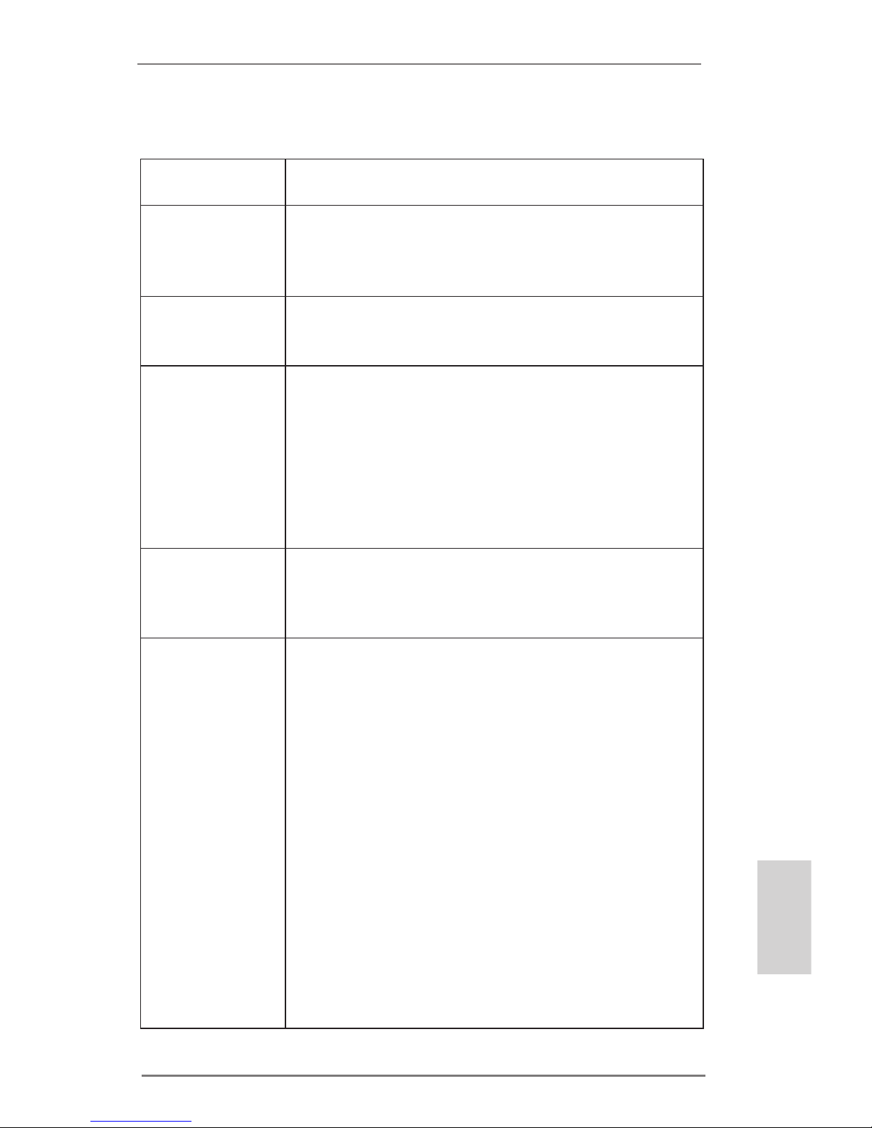
Pin1
alignment key
alignment key
Pin1
1155-Pin CPU
1155-Pin Socket
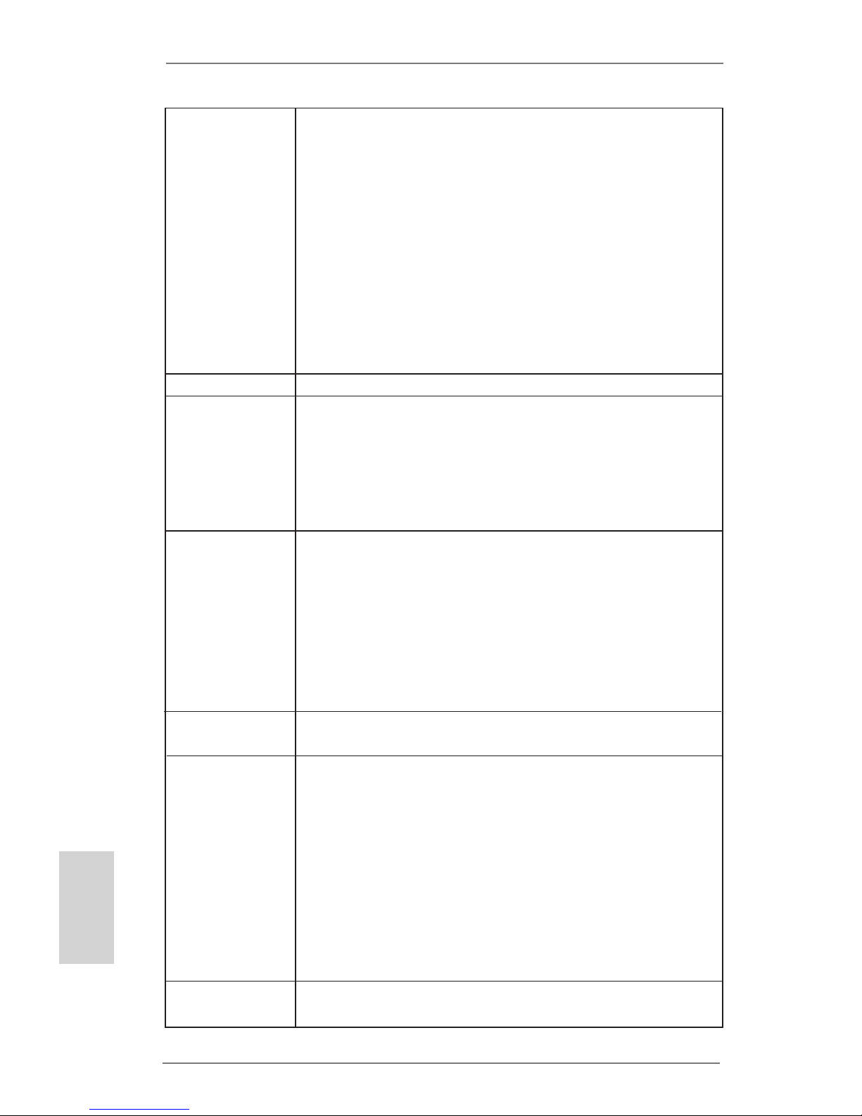
Step 3. Insert the 1155-Pin CPU:
Step 3-1. Hold the CPU by the edge where is
marked with black line.
Step 3-2. Orient the CPU with IHS (Integrated
Heat Sink) up. Locate Pin1 and the
two orientation key notches.
For proper inserting, please ensure to match the two orientation key
notches of the CPU with the two alignment keys of the socket.
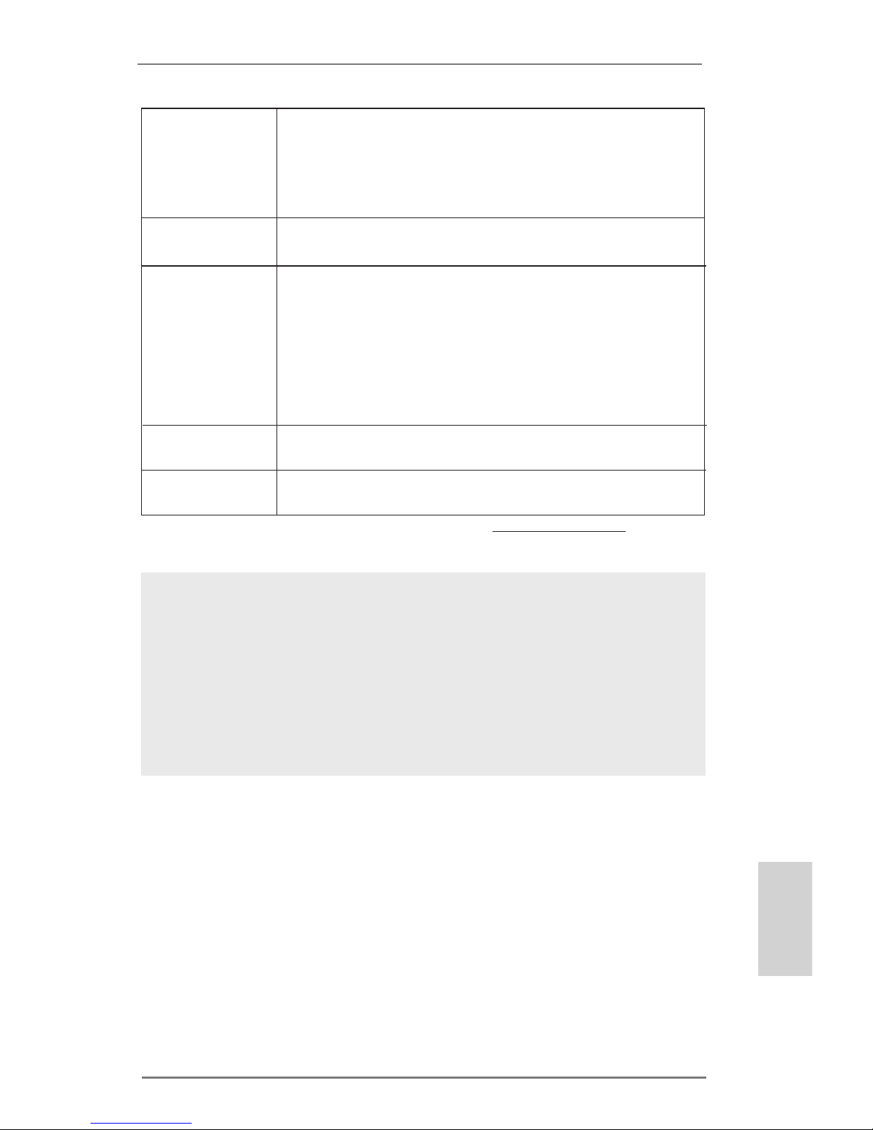
Step 3-3. Carefull y place the CPU into the
socket by using a purely vertical motion.
Step 3-4. Verify that the CPU is within the sock-
et and properly mated to the orient
keys.
Step 4. Close the socket:
Step 4-1. Rotate the load plate onto the IHS.
Step 4-2. While pressing down lightly on load
plate, engage the load lever.
Step 4-3. Secure load lever with load plate tab
under retention tab of load lever.
orientation key notch
orientation key notch
black line
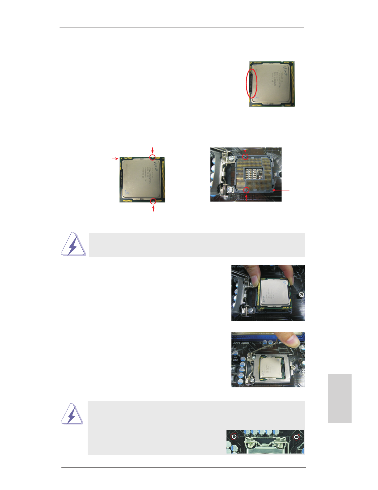
Please be noticed that this motherboard supports Combo Cooler
Option (C.C.O.), which provides the exible option to adopt three different CPU cooler types, Socket LGA 775, LGA 1155 and LGA 1156.
The white throughholes are for Socket LGA
1155/1156 CPU fan.

16
ASRock H61 Pro BTC Motherboard
English
2.4 Installation of CPU Fan and Heatsink
This motherboard is equipped with 1155-Pin socket that supports Intel 1155-Pin
CPU. Please adopt the type of heatsink and cooling fan compliant with Intel 1155Pin CPU to dissipate heat. Before you installed the heatsink, you need to spray
thermal interface material between the CPU and the heatsink to improve heat dissipation. Ensure that the CPU and the heatsink are securely fastened and in good
contact with each other. Then connect the CPU fan to the CPU_FAN connector
(CPU_FAN1, see page 2, No. 2).
For proper installation, please kindly refer to the instruction manuals of your
CPU fan and heatsink.
Below is an example to illustrate the installation of the heatsink for 1155-Pin CPU.
Step 1. Apply thermal interface material onto center of
IHS on the socket surface.
Step 2. Place the heatsink onto the socket. Ensure
fan cables are oriented on side closest to the
CPU fan connector on the motherboard (CPU_
FAN1, see page 2, No. 2).
Step 3. Align fasteners with the motherboard through-
holes.
Step 4. Rotate the fastener clockwise, then press
down on fastener caps with thumb to install
and lock. Repeat with remaining fasteners.
If you press down the fasteners without rotating them clockwise, the
heatsink cannot be secured on the motherboard.
Step 5. Connect fan header with the CPU fan connector on the motherboard.
Step 6. Secure excess cable with tie-wrap to ensure cable does not interfere with
fan operation or contact other components.
App ly The rma l
Int erf ace Ma ter ia l
Fan ca ble s on sid e
clo ses t to MB hea der
Fas ten er slo ts
poi nti ng str ai ght ou t
Pre ss Dow n
(4 Pla ces )

17
ASRock H61 Pro BTC Motherboard
English
2.5 Installation of Memory Modules (DIMM)
This motherboard provides two 240-pin DDR3 (Double Data Rate 3) DIMM slots,
and supports Dual Channel Memory Technology. For dual channel configuration,
you always need to install two identical (the same brand, speed, size and chiptype) memory modules in the DDR3 DIMM slots to activate Dual Channel Memory
Technology. Otherwise, it will operate at single channel mode.
1. It is not allowed to install a DDR or DDR2 memory module into
DDR3 slot;otherwise, this motherboard and DIMM may be
damaged.
2. If you install only one memory module or two non-identical
memory modules, it is unable to activate the Dual Channel
Memory Technology.
3. Some DDR3 1GB double-sided DIMMs with 16 chips may not
work on this motherboard. It is not recommended to install them
on this motherboard.
Installing a DIMM
Please make sure to disconnect power supply before adding or
removing DIMMs or the system components.
Step 1. Unlock a DIMM slot by pressing the retaining clips outward.
Step 2. Align a DIMM on the slot such that the notch on the DIMM matches the
break on the slot.
The DIMM only ts in one correct orientation. It will cause permanent
damage to the motherboard and the DIMM if you force the DIMM into
the slot at incorrect orientation.
Step 3. Firmly insert the DIMM into the slot until the retaining clips at both ends
fully snap back in place and the DIMM is properly seated.

18
ASRock H61 Pro BTC Motherboard
English
2.6 Expansion Slots (PCI Express Slots)
There are 6 PCI Express slots on this motherboard.
PCIE slots:
PCIE1 / PCIE3 / PCIE4 / PCIE5 / PCIE6 (PCIE 2.0 x1 slot) is used for
PCI Express cards with x1 lane width cards.
PCIE2 (PCIE 3.0 x16 slot) is used for PCI Express x16 lane width
graphics cards.
Only PCIE2 slot supports Gen 3 speed. To run the PCI Express in Gen
3 speed, please install an Ivy Bridge CPU. If you install a Sandy Bridge
CPU, the PCI Express will run only at PCI Express Gen 2 speed.
Installing an expansion card
Step 1. Before installing the expansion card, please make sure that the power
supply is switched off or the power cord is unplugged. Please read the
documentation of the expansion card and make necessary hardware
settings for the card before you start the installation.
Step 2. Remove the system unit cover (if your motherboard is already installed
in a chassis).
Step 3. Remove the bracket facing the slot that you intend to use. Keep the
screws for later use.
Step 4. Align the card connector with the slot and press rmly until the card is
completely seated on the slot.
Step 5. Fasten the card to the chassis with screws.
Step 6. Replace the system cover.

19
ASRock H61 Pro BTC Motherboard
English
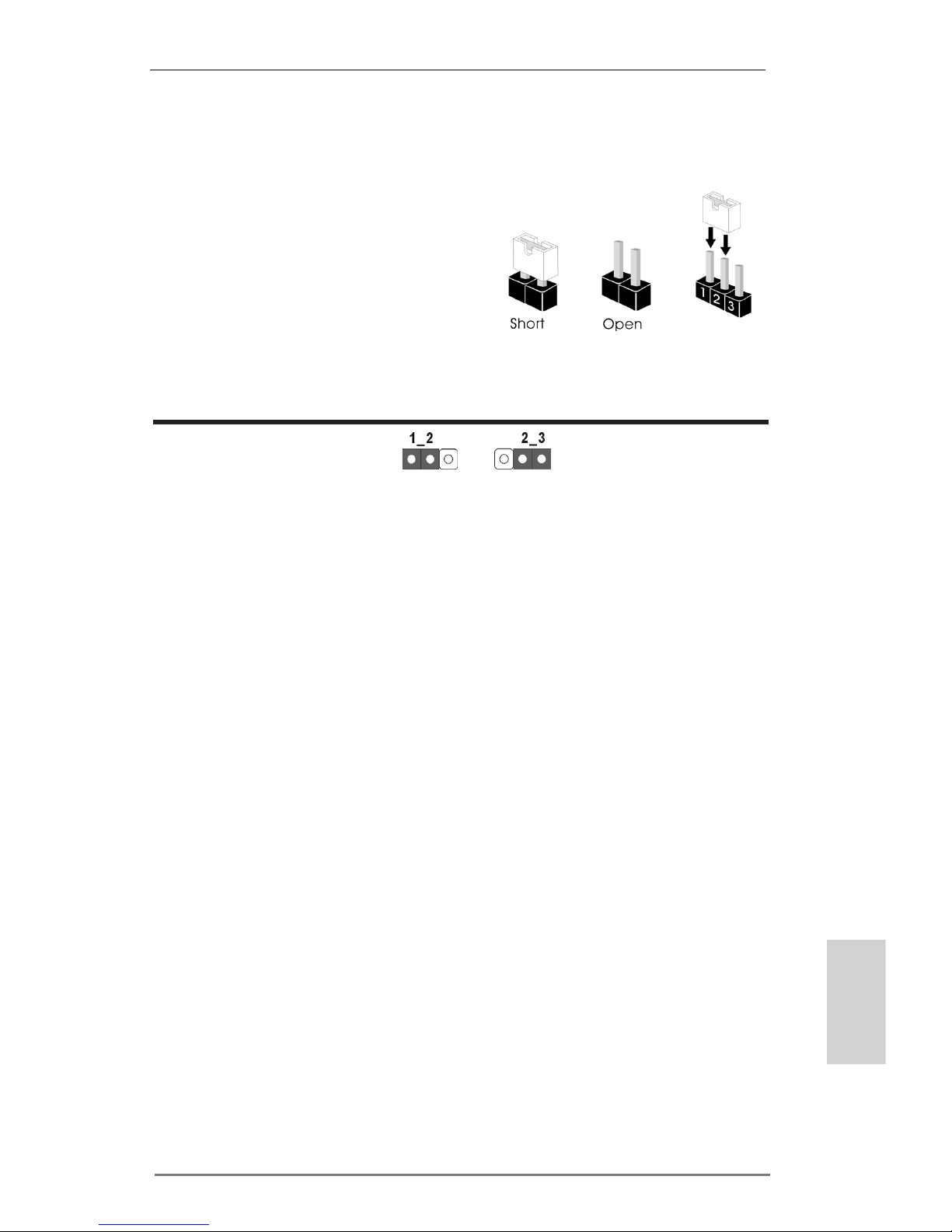
2.7 Jumpers Setup
The illustration shows how jumpers are
setup. When the jumper cap is placed on
pins, the jumper is “Short”. If no jumper cap
is placed on pins, the jumper is “Open”. The
illustration shows a 3-pin jumper whose
pin1 and pin2 are “Short” when jumper cap
is placed on these 2 pins.
Jumper Setting Description
Clear CMOS Jumper
(CLRCMOS1)
(see p.2, No. 9)
Note: CLRCMOS1 allows you to clear the data in CMOS. To clear and reset the
system parameters to default setup, please turn off the computer and unplug
the power cord from the power supply. After waiting for 15 seconds, use a
jumper cap to short pin2 and pin3 on CLRCMOS1 for 5 seconds. However,
please do not clear the CMOS right after you update the BIOS. If you need
to clear the CMOS when you just nish updating the BIOS, you must boot
up the system rst, and then shut it down before you do the clear-CMOS action. Please be noted that the password, date, time, user default prole, 1394
GUID and MAC address will be cleared only if the CMOS battery is removed.
Clear CMOSDefault
20
ASRock H61 Pro BTC Motherboard
English
2.8 Onboard Headers and Connectors
Onboard headers and connectors are NOT jumpers. Do NOT place
jumper caps over these headers and connectors. Placing jumper caps
over the headers and connectors will cause permanent damage of the
motherboard!
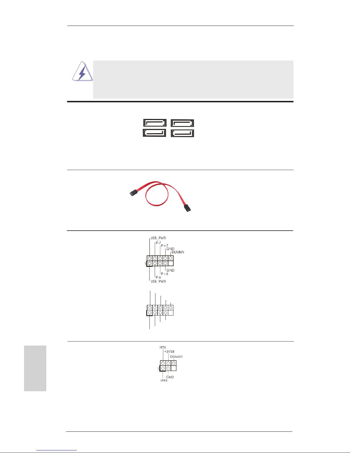
Serial ATAII Connectors These four Serial ATAII
(SATA2_0: see p.2, No. 12)
(SATAII) connectors support
(SATA2_1: see p.2, No. 15)
SATA data cables for internal
(SATA2_2: see p.2, No. 11)
storage devices. The current
(SATA2_3: see p.2, No. 14)
SATAII interface allows up to
3.0 Gb/s data transfer rate.
Serial ATA (SATA) Either end of the SATA data
Data Cable cable can be connected to the
(Optional)
SATA / SATAII hard disk or the
SATAII connector on this
motherboard.
USB 2.0 Headers Besides six default USB 2.0
(9-pin USB6_7)
ports on the I/O panel, there
(see p.2 No. 18)
are two USB 2.0 headers on
this motherboard. Each
USB 2.0 header can support
two USB 2.0 ports.
(9-pin USB8_9)
(see p.2 No. 17)
1
US B _P WR
P-8
GND
DUMMY
US B _P WR
P+8
GND
P-9
P+9
SATA2_2
SATA2_3
SATA2_0
SATA2_1
Infrared Module Header This header supports an
(5-pin IR1)
optional wireless transmitting
(see p.2 No. 13)
and receiving infrared module.

21
ASRock H61 Pro BTC Motherboard
English
J_ S EN SE
OU T 2_ L
1
MI C _R ET
PR E SE NC E#
GND
OU T 2_ R
MI C 2_ R
MI C 2_ L
OUT_RET
Front Panel Audio Header This is an interface for front
(9-pin HD_AUDIO1)
panel audio cable that allows
(see p.2 No. 20)
convenient connection and
control of audio devices.
1. High Denition Audio supports Jack Sensing, but the panel wire on
the chassis must support HDA to function correctly. Please follow the
instruction in our manual and chassis manual to install your system.
2. If you use AC’97 audio panel, please install it to the front panel audio
header as below:
A. Connect Mic_IN (MIC) to MIC2_L.
B. Connect Audio_R (RIN) to OUT2_R and Audio_L (LIN) to OUT2_L.
C. Connect Ground (GND) to Ground (GND).
D. MIC_RET and OUT_RET are for HD audio panel only. You don’t
need to connect them for AC’97 audio panel.
System Panel Header This header accommodates
(9-pin PANEL1)
several system front panel
(see p.2 No. 16)
functions.
Connect the power switch, reset switch and system status indicator on the
chassis to this header according to the pin assignments below. Note the
positive and negative pins before connecting the cables.
PWRBTN (Power Switch):
Connect to the power switch on the chassis front panel. You may congure
the way to turn off your system using the power switch.
RESET (Reset Switch):
Connect to the reset switch on the chassis front panel. Press the reset
switch to restart the computer if the computer freezes and fails to perform a
normal restart.
PLED (System Power LED):
Connect to the power status indicator on the chassis front panel. The LED
is on when the system is operating. The LED keeps blinking when the sys-
tem is in S1 sleep state. The LED is off when the system is in S3/S4 sleep
state or powered off (S5).
HDLED (Hard Drive Activity LED):
Connect to the hard drive activity LED on the chassis front panel. The LED
is on when the hard drive is reading or writing data.

22
ASRock H61 Pro BTC Motherboard
English
Chassis Speaker Header Please connect the chassis
(4-pin SPEAKER 1)
speaker to this header.
(see p.2 No. 10)
CPU Fan Connectors Please connect the CPU fan
(4-pin CPU_FAN1)
cable to the connector and
(see p.2 No. 2)
match the black wire to the
ground pin.
Chassis and Power Fan Connectors Please connect the fan cables
(4-pin CHA_FAN1)
to the fan connectors and
(see p.2 No. 6)
match the black wire to the
ground pin.
(4-pin PWR_FAN1)
(see p.2 No. 28)
Though this motherboard provides 4-Pin CPU fan (Quiet Fan) support, the 3-Pin
CPU fan still can work successfully even without the fan speed control function.
If you plan to connect the 3-Pin CPU fan to the CPU fan connector on this
motherboard, please connect it to Pin 1-3.
3-Pin Fan Installation
Pin 1-3 Connected
ATX Power Connector Please connect an ATX power
(24-pin ATXPWR1)
supply to this connector.
(see p.2 No. 5)
12 124
13
20-Pin ATX Power Supply Installation
Though this motherboard provides 24-pin ATX power connector,
it can still work if you adopt a traditional 20-pin ATX power supply.
To use the 20-pin ATX power supply, please plug your
power supply along with Pin 1 and Pin 13.
12
1
24
13
The front panel design may differ by chassis. A front panel module mainly
consists of power switch, reset switch, power LED, hard drive activity LED,
speaker and etc. When connecting your chassis front panel module to this
header, make sure the wire assignments and the pin assign-ments are
matched correctly.
GND
+12V
CPU_FAN _S PE ED
FAN _S PE ED _C ON TR OL
1 2 3 4

23
ASRock H61 Pro BTC Motherboard
English
Serial Port Header This COM1 header supports a
(9-pin COM1)
serial port module.
(see p.2 No. 19)
ATX 12V Power Connector Please connect an ATX 12V
(8-pin ATX12V1)
power supply to this connector.
(see p.2 No. 3)
4-Pin ATX 12V Power Supply Installation
Though this motherboard provides 8-pin ATX 12V power connector, it can still work
if you adopt a traditional 4-pin ATX 12V power supply. To use the 4-pin ATX power
supply, please plug your power supply along with Pin 1 and Pin 5.
8 5
4 1
8 5
4 1
SLI/XFire Power Connectors It is not necessary to use this
(4-pin SLI/XFIRE_PWR1)
connector, but please connect it
(see p.2 No. 29)
with a hard disk power
connecor when two graphics
(4-pin SLI/XFIRE_PWR2)
cards are plugged to this
(see p.2 No. 27)
motherboard.

24
ASRock H61 Pro BTC Motherboard
English
3. BIOS Information
The Flash Memory on the motherboard stores BIOS Setup Utility. When you start up
the computer, please press <F2> or <Del> during the Power-On-Self-Test (POST)
to enter BIOS Setup utility; otherwise, POST continues with its test routines. If you
wish to enter BIOS Setup after POST, please restart the system by pressing <Ctl>
+ <Alt> + <Delete>, or pressing the reset button on the system chassis. The BIOS
Setup program is designed to be user-friendly. It is a menu-driven program, which
allows you to scroll through its various sub-menus and to select among the prede-
termined choices. For the detailed information about BIOS Setup, please refer to the
User Manual (PDF le) contained in the Support CD.
4. Software Support CD information
This motherboard supports various Microsoft
®
Windows® operating systems: 8 / 8
64-bit / 7 / 7 64-bit / VistaTM / Vista
TM
64-bit / XP / XP 64-bit. The Support CD that
came with the motherboard contains necessary drivers and useful utilities that will
enhance motherboard features. To begin using the Support CD, insert the CD into
your CD-ROM drive. It will display the Main Menu automatically if “AUTORUN” is
enabled in your computer. If the Main Menu does not appear automatically, locate
and double-click on the le “ASSETUP.EXE” from the BIN folder in the Support CD
to display the menus.

25
ASRock H61 Pro BTC Motherboard
Deutsch
1. Einführung
Wir danken Ihnen für den Kauf des ASRock H61 Pro BTC Motherboard, ein zuverlässiges Produkt, welches unter den ständigen, strengen Qualitätskontrollen von
ASRock gefertigt wurde. Es bietet Ihnen exzellente Leistung und robustes Design,
gemäß der Verpflichtung von ASRock zu Qualität und Halbarkeit. Diese Schnellinstallationsanleitung führt in das Motherboard und die schrittweise Installation
ein. Details über das Motherboard nden Sie in der Bedienungsanleitung auf der
Support-CD.
Da sich Motherboard-Spezikationen und BIOS-Software verändern
können, kann der Inhalt dieses Handbuches ebenfalls jederzeit geändert
werden. Für den Fall, dass sich Änderungen an diesem Handbuch
ergeben, wird eine neue Version auf der ASRock-Website, ohne weitere
Ankündigung, verfügbar sein. Die neuesten Grakkarten und unterstützten
CPUs sind auch auf der ASRock-Website aufgelistet.
ASRock-Website: http://www.asrock.com
Wenn Sie technische Unterstützung zu Ihrem Motherboard oder spezische
Informationen zu Ihrem Modell benötigen, besuchen Sie bitte unsere
Webseite:
www.asrock.com/support/index.asp
1.1 Kartoninhalt
ASRock H61 Pro BTC Motherboard (ATX-Formfaktor)
ASRock H61 Pro BTC Schnellinstallationsanleitung
ASRock H61 Pro BTC Support-CD
Zwei Serial ATA (SATA) -Datenkabel (optional)
Ein I/O Shield
ASRock erinnert...
Zur besseren Leistung unter Windows® 8 / 8 64 Bit / 7 / 7 64 Bit / Vista
TM
/
VistaTM 64 Bit empfehlen wir, die Speicherkonguration im BIOS auf den
AHCI-Modus einzustellen. Hinweise zu den BIOS-Einstellungen nden
Sie in der Bedienungsanleitung auf der mitgelieferten CD.

26
ASRock H61 Pro BTC Motherboard
1.2 Spezikationen
Plattform - ATX-Formfaktor
- Alle Feste Kondensatordesign
CPU - Unterstützt Intel® CoreTM i7- / i5- / i3- / Xeon®- / Pentium®- /
Celeron®-Prozessoren der 3ten und 2ten Generation im
LGA1155-Package
- Unterstützt Intel® Turbo Boost 2.0-Technologie
- Unterstützt freigegebene CPU der K-Serie
Chipsatz - Intel® H61
- Unterstützt Intel® Rapid Start Technology und Smart
Connect Technology
Speicher - Unterstützung von Dual-Kanal-Speichertechnologie
- 2 x Steckplätze für DDR3
- Unterstützt DDR3 1600/1333/1066 non-ECC, ungepufferter
Speicher (DDR3 1600 mit Intel® Ivy Bridge-Prozessor,
DDR3 1333 mit Intel® Sandy Bridge-Prozessor)
- Max. Kapazität des Systemspeichers: 16GB
- Unterstützt Intel® Extreme Memory Prole (XMP)1.3/1.2 mit
Intel® Ivy Bridge-Prozessor
Erweiterungs- - 1 x PCI Express 3.0 x16-Steckplatz (PCIE2 für x16-Modus)
steckplätze * PCIE 3.0 wird nur mit Intel® Ivy Bridge-Prozessor
unterstützt. Mit Intel® Sandy Bridge-Prozessor wird nur
PCIE 2.0 unterstützt.
- 5 x PCI Express 2.0 x1-Steckplätze
Onboard-VGA * Integrierte Intel® HD-Grakdarstellungen und die VGA Ausgänge können nur durch GPU-integrierte Prozessoren
unterstützt werden.
- Unterstützt hochauösende integrierte Intel®-Graklösungen:
Intel® Quick-Sync-Video 2.0, Intel® InTruTM 3D, Intel® Clear Video-Technik (HD), Intel® InsiderTM, Intel® HD Graphics
2500/4000 mit Intel® Ivy Bridge-Prozessor
- Unterstützt hochauösende integrierte Intel®-Graklösungen:
Intel® Quick-Sync-Video, Intel® InTruTM 3D, Intel® Clear Video-Technik (HD), Intel® HD Graphics 2000/3000, Intel®
Advanced Vector Extensions (AVX) mit Intel® Sandy Bridge Prozessor
- Pixel Shader 5.0, DirectX 11 mit Intel® Ivy Bridge-Prozessor,
Pixel Shader 4.1, DirectX 10.1 mit Intel® Sandy Bridge Prozessor
Deutsch

27
ASRock H61 Pro BTC Motherboard
Deutsch
- Maximal gemeinsam genutzter Speicher 1760MB mit Intel®
Ivy Bridge-Prozessor. Maximal gemeinsam genutzter
Speicher 1759MB mit Intel® Sandy Bridge-Prozessor.
- Doppel-VGA Ausgabe: unterstützt HDMI und D-Sub Ports
durch unabhängige Bildschirmanzeige Kontrolleure
- Unterstützt HDMI mit einer maximalen Auösung von
1920 x 1200 bei 60 Hz
- Unterstützt D-Sub mit einer maximalen Auösung von
2048 x 1536 bei 75 Hz
- Unterstützt Auto Lip Sync, Deep Color (12bpc), xvYCC und
HBR (High Bit Rate-Audio) mit HDMI (kompatibler HDMI-
Bildschirm erforderlich)
- Unterstützt HDCP-Funktion mit HDMI-Port
- Unterstutzt 1080p Blu-ray (BD) / HD-DVD-Wiedergabe mit
HDMI-Port
Audio - 5.1 CH HD Audio (VIA® VT1705 Audio Codec)
LAN - PCIE x1 Gigabit LAN 10/100/1000 Mb/s
- Realtek RTL8111E
- Unterstützt Wake-On-LAN
- Unterstützt LAN-Kabelerkennung
- Unterstützt energieefzientes Ethernet 802.3az
- Unterstützt PXE
E/A-Anschlüsse - 1 x PS/2-Mausanschluss
an der - 1 x PS/2-Tastaturanschluss
Rückseite - 1 x D-Sub port
- 1 x HDMI port
- 6 x Standard-USB 2.0-Anschlüsse
- 1 x RJ-45 LAN Port mit LED (ACT/LINK LED und SPEED
LED)
- HD Audiobuchse: Audioeingang / Lautsprecher vorne /
Mikrofon
Speichergerät - 4 x SATA2 3,0 GB/s-Anschlüsse, unterstützen NCQ-, AHCI-
und „Hot Plug“ (Hot-Plugging)- Funktionen
Anschlüsse - 1 x Infrarot-Modul-Header
- 1 x COM-Anschluss-Header
- 1 x CPUlüfter-Anschluss (4-pin)
- 1 x Gehäuselüfter-Anschluss (4-pin)
- 1 x Stromlüfter-Anschluss (4-pin)
- 1 x 24-pin ATX-Netz-Header
- 1 x 8-pin anschluss für 12V-ATX-Netzteil
- 2 x SLI/XFire-Netz-Header
28
ASRock H61 Pro BTC Motherboard
Deutsch
- 1 x Anschluss für Audio auf der Gehäusevorderseite
- 2 x USB 2.0-Anschlüsse (Unterstützung 4 zusätzlicher
USB 2.0-Anschlüsse)
BIOS - 32Mb AMIs Legal BIOS UEFI mit GUI-Unterstützung
- Unterstützung für “Plug and Play”
- ACPI 1.1-Weckfunktionen
- JumperFree-Übertaktungstechnologie
- SMBIOS 2.3.1
- IGPU, DRAM, PCH, CPU PLL, VTT, VCCSA
Stromspannung Multianpassung
CD d’assistance - Pilotes, utilitaires, logiciel anti-virus (version d’évaluation),
Google Chrome Browser und Toolbar
Hardware Monitor - Überwachung der CPU-Temperatur
- Motherboardtemperaturerkennung
- Drehzahlmessung für CPU/Gehäuse/Stromlüfter
- Geräuscharmer CPU-/Gehäuselüfter (ermöglicht die au
tomatische Anpassung der Gehäuselüftergeschwindigkeit
durch CPU- Temperatur)
- Mehrstuge Geschwindigkeitsteuerung für CPU-/
Gehäuselüfter
- Spannungsüberwachung: +12V, +5V, +3.3V, Vcore
Betriebssysteme - Unterstützt Microsoft
®
Windows® 8 / 8 64-Bit / 7 / 7 64-Bit /
VistaTM / Vista
TM
64-Bit / XP / XP 64-Bit
Zertizierungen - FCC, CE, WHQL
- Gemäß Ökodesign-Richtlinie (ErP/EuP) (Stromversorgung
gemäß Ökodesign-Richtlinie (ErP/EuP) erforderlich)
* Für die ausführliche Produktinformation, besuchen Sie bitte unsere Website:
http://www.asrock.com
29
ASRock H61 Pro BTC Motherboard
Deutsch
1.3 Einstellung der Jumper
Die Abbildung verdeutlicht, wie Jumper
gesetzt werden. Werden Pins durch
Jumperkappen verdeckt, ist der Jumper
“Gebrückt”. Werden keine Pins durch
Jumperkappen verdeckt, ist der Jumper
“Offen”. Die Abbildung zeigt einen 3-Pin
Jumper dessen Pin1 und Pin2 “Gebrückt” sind, bzw. es bendet sich eine
Jumper-Kappe auf diesen beiden Pins.
Jumper Einstellun Beschreibung
CMOS löschen
(CLRCMOS1, 3-Pin jumper)
(siehe S.2, No. 9)
Hinweis:
CLRCMOS1 ermöglicht Ihnen die Löschung der Daten im CMOS. Zum
Löschen und Zurücksetzen der Systemparameter auf die Standardeinrichtung
schalten Sie den Computer bitte aus und trennen das Netzkabel von der
Stromversorgung. Warten Sie 15 Sekunden, schließen Sie dann Pin2 und
Pin3 am CLRCMOS1 über einen Jumper fünf Sekunden lang kurz. Sie
sollten das CMOS allerdings nicht direkt nach der BIOS-Aktualisierung
löschen. Wenn Sie das CMOS nach Abschluss der BIOS-Aktualisierung
löschen müssen, fahren Sie zuerst das System hoch. Fahren Sie es dann
vor der CMOS-Löschung herunter. Bitte beachten Sie, dass Kennwort,
Datum, Uhrzeit, benutzerdeniertes Prol, 1394 GUID und MAC-Adresse
nur gelöscht werden, wenn die CMOS-Batterie entfernt wird.
CMOS
löschen
DefaultEinstellung

30
ASRock H61 Pro BTC Motherboard
1.4 Integrierte Header und Anschlüsse
Integrierte Header und Anschlüsse sind KEINE Jumper. Setzen Sie KEINE Jumperkappen auf diese Header und Anschlüsse. Wenn Sie Jumperkappen auf Header und Anschlüsse setzen, wird das Motherboard
unreparierbar beschädigt!
Seriell-ATAII-Anschlüsse Diese vier Serial ATAII-
(SATA2_0: siehe S.2 - No. 12)
(SATAII-) Verbínder
(SATA2_1: siehe S.2 - No. 15)
unterstützten SATA-Datenkabel
(SATA2_2: siehe S.2 - No. 11)
für interne
(SATA2_3: siehe S.2 - No. 14)
Massenspeichergeräte. Die
aktuelle SATAII-Schnittstelle
ermöglicht eine
Datenübertragungsrate bis
3,0 Gb/s.
Serial ATA- (SATA-) SJedes Ende des SATA
Datenkabel Datenkabels kann an die SATA
(Option)
/ SATAII Festplatte
oder das SATAII
Verbindungsstück auf
dieser Hauptplatine
angeschlossen werden.
USB 2.0-Header Zusätzlich zu den sechs
(9-pol. USB6_7)
üblichen USB 2.0-Ports an den
(siehe S.2 - No. 18)
I/O-Anschlüssen benden sich
zwei USB 2.0-
Anschlussleisten am
Motherboard. Pro USB 2.0-
(9-pol. USB8_9)
Anschlussleiste werden zwei
(siehe S.2 - No. 17)
USB 2.0-Ports unterstützt.
1
US B _P WR
P-8
GND
DUMMY
US B _P WR
P+8
GND
P-9
P+9
Deutsch
Infrarot-Modul-Header Dieser Header unterstützt ein
(5-pin IR1)
optionales, drahtloses Sende-
(siehe S.2 - No. 13)
und Empfangs-Infrarotmodul.
SATA2_2
SATA2_3
SATA2_0
SATA2_1
 Loading...