


H61M-ITX
1
ASRock H61M-ITX Motherboard
English
Copyright Notice:
No part of this installation guide may be reproduced, transcribed, transmitted, or trans-
lated in any language, in any form or by any means, except duplication of documentation
by the purchaser for backup purpose, without written consent of ASRock Inc.
Products and corporate names appearing in this guide may or may not be registered
trademarks or copyrights of their respective companies, and are used only for identifi ca-
tion or explanation and to the owners’ benefi t, without intent to infringe.
Disclaimer:
Specifi cations and information contained in this guide are furnished for informational use
only and subject to change without notice, and should not be constructed as a commit-
ment by ASRock. ASRock assumes no responsibility for any errors or omissions that may
appear in this guide.
With respect to the contents of this guide, ASRock does not provide warranty of any kind,
either expressed or implied, including but not limited to the implied warranties or condi-
tions of merchantability or fi tness for a particular purpose. In no event shall ASRock, its
directors, offi cers, employees, or agents be liable for any indirect, special, incidental, or
consequential damages (including damages for loss of profi ts, loss of business, loss of
data, interruption of business and the like), even if ASRock has been advised of the pos-
sibility of such damages arising from any defect or error in the guide or product.
This device complies with Part 15 of the FCC Rules. Operation is subject to the following
two conditions:
(1) this device may not cause harmful interference, and
(2) this device must accept any interference received, including interference that
may cause undesired operation.
CALIFORNIA, USA ONLY
The Lithium battery adopted on this motherboard contains Perchlorate, a toxic substance
controlled in Perchlorate Best Management Practices (BMP) regulations passed by the
California Legislature. When you discard the Lithium battery in California, USA, please
follow the related regulations in advance.
“Perchlorate Material-special handling may apply, see
www.dtsc.ca.gov/hazardouswaste/perchlorate”
ASRock Website: http://www.asrock.com
Published May 2012
Copyright
©
2012 ASRock INC. All rights reserved.
2
ASRock H61M-ITX Motherboard
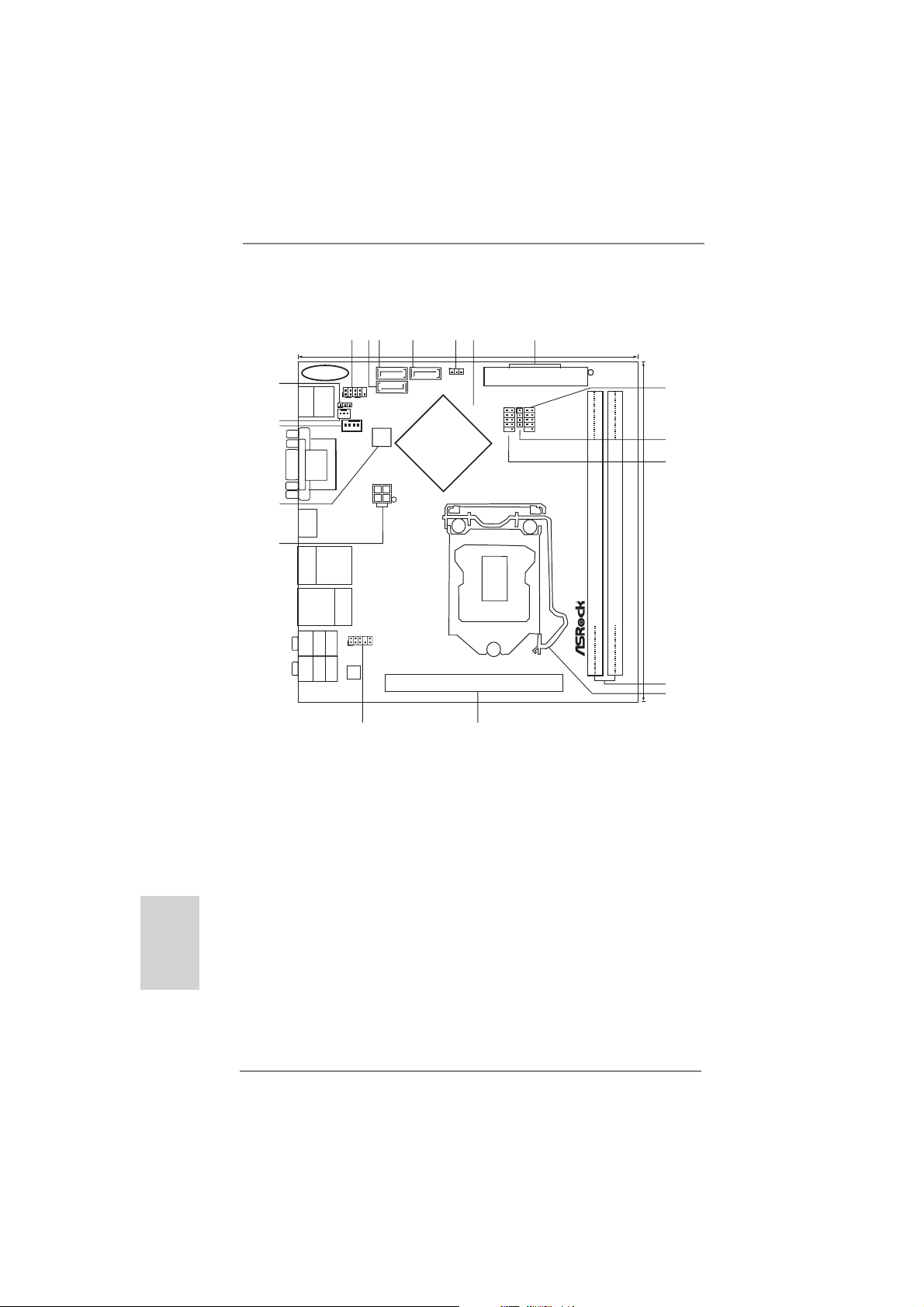
Motherboard Layout
English
1 System Panel Header (PANEL1, White) 12 1155-Pin CPU Socket
2 SATA2 Connector (SATA_1 (PORT 1), Blue) 13 PCI Express 2.0 x16 Slot (PCIE1, Blue)
3 SATA2 Connector (SATA_0 (PORT 0), Blue) 14 Front Panel Audio Header
4 SATA2 Connector (SATA_2 (PORT 4), Blue) (HD_AUDIO1, White)
5 Clear CMOS Jumper (CLRCMOS1) 15 ATX 12V Power Connector (ATX12V1)
6 Intel H61 Chipset 16 32Mb SPI Flash
7 ATX Power Connector (ATXPWR1) 17 CPU Fan Connector (CPU_FAN1)
8 USB 2.0 Header (USB8_9, Blue) 18 Chassis Fan Connector (CHA_FAN1)
9 Consumer Infrared Module Header (CIR1) 19 Power LED Header (PLED1)
10 USB 2.0 Header (USB6_7, Blue)
11 2 x 240-pin DDR3 DIMM Slots
(Dual Channel: DDR3_A1, DDR3_B1, Blue)
DDR3_A1 (64bit, 240-pin module)
DDR3_B1 (64bit, 240-pin module)
Intel
H61
H61M-ITX
PCIE1
AUDIO
CODEC
32Mb
BIOS
17.0cm (6.7in)
17.0cm (6.7in)
ATXPWR1
ATX12V1
CMOS
Battery
USB8_9
1
1
USB6_7
HDLED RESET
PLED PWRBTN
PANEL1
CLRCMOS1
1
PLED1
1
1
CIR1
1
CHA_FAN1
CPU_FAN1
1
HD_AUDIO1
Top:
CTR BASS
Center:
REAR SPK
Bottom:
Optical
SPDIF
Top:
LINE IN
Center:
FRONT
Bottom:
MIC IN
Top:
RJ-45
USB 3.0
T:USB4
B: USB5
VGA1
DVI_CON1
HDMI1
USB 2.0
T: U SB 0
B: USB1
PS2
Keyboard
HDMI 1.4a USB 3.0 RoHS
Designed inTaipei
1
2
3
4
5
6
11
12
10
7
8
9
14
13
15
16
17
18
SATA_1(PORT1)
ESATA1
USB 2.0
T: U SB 2
B: USB3
SATA_0(PORT0) SATA_2(PORT4)
Gigabit LAN
X
Fast USB
DDR3
19
ErP/EuP Ready
3
ASRock H61M-ITX Motherboard
English
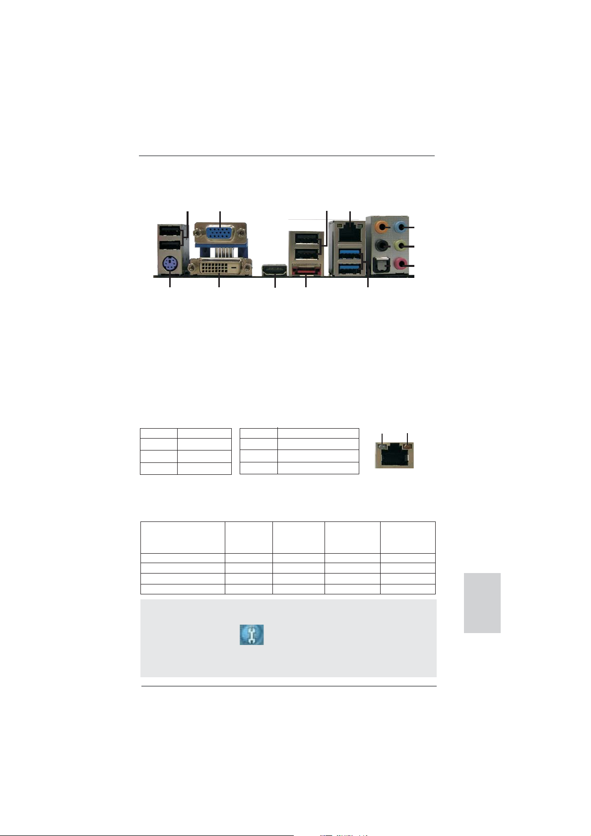
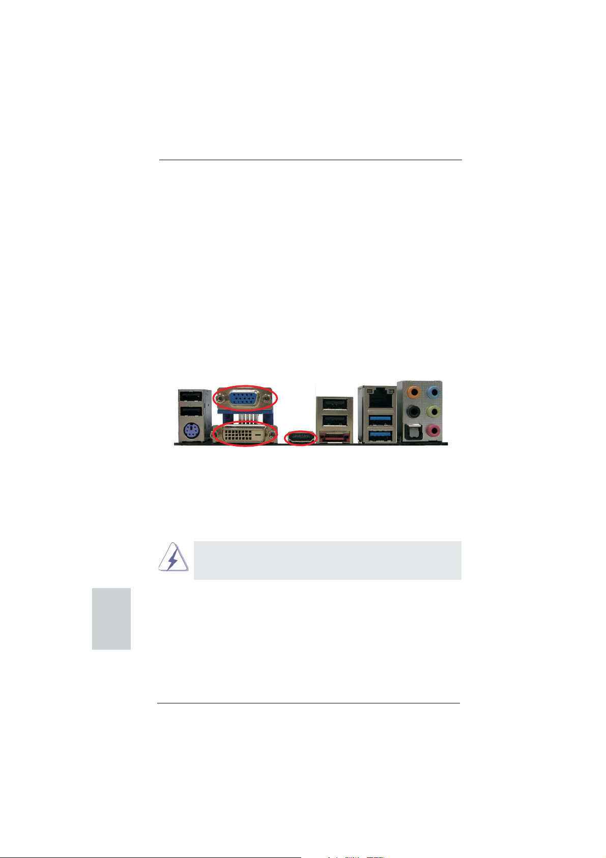
I/O Panel
**
If you use 2-channel speaker, please connect the speaker’s plug into “Front Speaker Jack”.
See the table below for connection details in accordance with the type of speaker you use.
TABLE for Audio Output Connection
Audio Output Channels Front Speaker Rear Speaker Central / Bass Line In or
(No. 9) (No. 6) (No. 5) Side Speaker
(No. 8)
2 V -- -- --
4 V V -- --
6 V V V --
8 V V V V
* There are two LED next to the LAN port. Please refer to the table below for the LAN port LED
indications.
LAN Port LED Indications
Activity/Link LED SPEED LED
Status Description Status Description
Off No Link Off 10Mbps connection
Blinking Data Activity Orange 100Mbps connection
On Link Green 1Gbps connection
ACT/LINK
LED
SPEED
LED
LAN Port
1
2
5
3
6
7
8
9
10
11
13
14
12
4
15
1 USB 2.0 Ports (USB01) ** 9 Front Speaker (Lime)
2 D-Sub Port 10 Microphone (Pink)
3 USB 2.0 Ports (USB23) 11 USB 3.0 Ports (USB45)
* 4 LAN RJ-45 Port 12 eSATA2 Port
5 Central / Bass (Orange) 13 HDMI Port
6 Rear Speaker (Black) 14 DVI-D Port
7 Optical SPDIF Out Port 15 PS/2 Keyboard Port (Purple)
8 Line In (Light Blue)
To enable Multi-Streaming function, you need to connect a front panel audio cable to the front
panel audio header. After restarting your computer, you will fi nd “Mixer” tool on your system.
Please select “Mixer ToolBox” , click “Enable playback multi-streaming”, and click
“ok”. Choose “2CH”, “4CH”, “6CH”, or “8CH” and then you are allowed to select “Realtek HDA
Primary output” to use Rear Speaker, Central/Bass, and Front Speaker, or select “Realtek
HDA Audio 2nd output” to use front panel audio.
4
ASRock H61M-ITX Motherboard
1. Introduction
Thank you for purchasing ASRock H61M-ITX motherboard, a reliable motherboard
produced under ASRock’s consistently stringent quality control. It delivers excellent
performance with robust design conforming to ASRock’s commitment to quality and
endurance.
This Quick Installation Guide contains introduction of the motherboard and step-by-
step installation guide. More detailed information of the motherboard can be found
in the user manual presented in the Support CD.
Because the motherboard specifi cations and the BIOS software might be
updated, the content of this manual will be subject to change without no-
tice. In case any modifi cations of this manual occur, the updated version
will be available on ASRock website without further notice. You may fi nd
the latest VGA cards and CPU support lists on ASRock website as well.
ASRock website http://www.asrock.com
If you require technical support related to this motherboard, please visit
our website for specifi c information about the model you are using.
www.asrock.com/support/index.asp
1.1 Package Contents
ASRock H61M-ITX Motherboard
(Mini-ITX Form Factor: 6.7-in x 6.7-in, 17.0 cm x 17.0 cm)
ASRock H61M-ITX Quick Installation Guide
ASRock H61M-ITX Support CD
2 x Serial ATA (SATA) Data Cables (Optional)
1 x 3.5mm Audio Cable (Optional)
1 x I/O Panel Shield
ASRock Reminds You...
To get better performance in Windows
®
7 / 7 64-bit / Vista
TM
/ Vista
TM
64-
bit, it is recommended to set the BIOS option in Storage Confi guration to
AHCI mode. For the BIOS setup, please refer to the “User Manual” in our
support CD for details.
English
5
ASRock H61M-ITX Motherboard
English
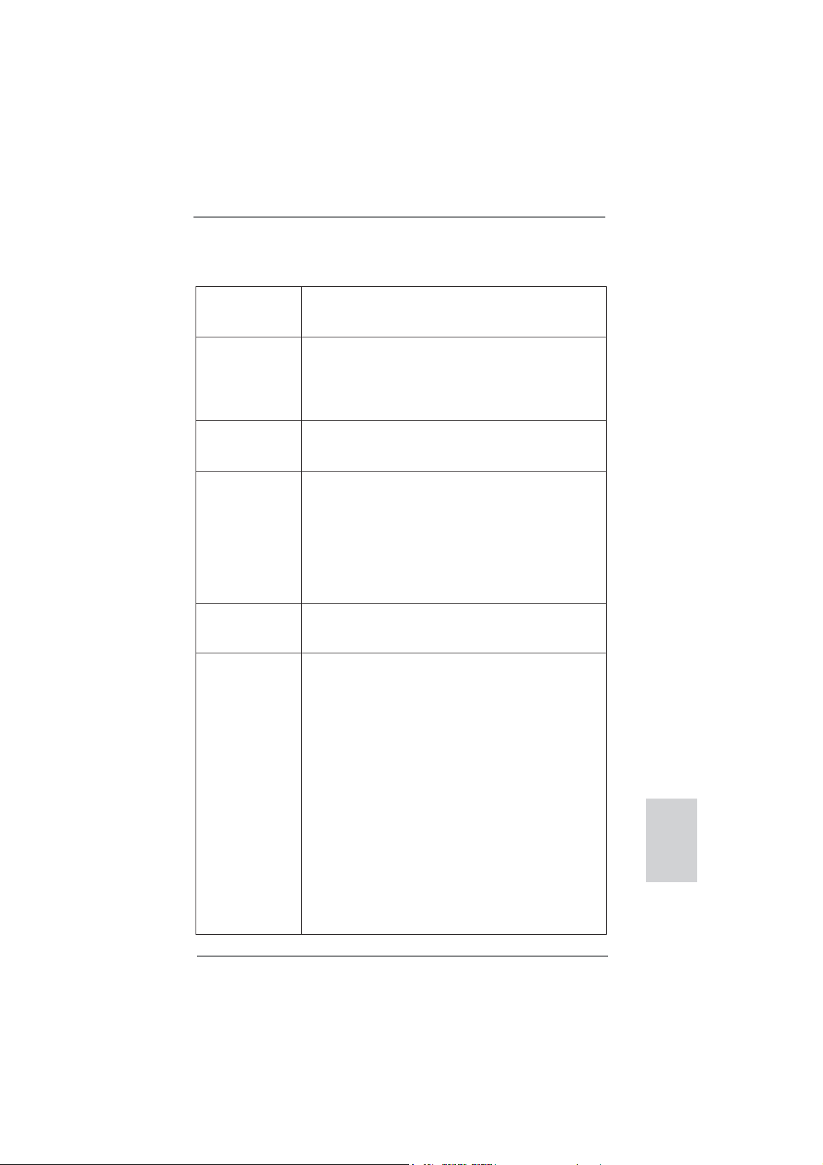
1.2 Specifications
Platform - Mini-ITX Form Factor: 6.7-in x 6.7-in, 17.0 cm x 17.0 cm
- All Solid Capacitor design (100% Japan-made high-quality
Conductive Polymer Capacitors)
CPU - Supports 3
rd
and 2
nd
Generation Intel
®
Core
TM
i7 / i5 / i3 in
LGA1155 Package
- Supports Intel
®
Turbo Boost 2.0 Technology
- Supports K-Series unlocked CPU
- Supports Hyper-Threading Technology (see CAUTION 1)
Chipset - Intel
®
H61
- Supports Intel
®
Rapid Start Technology and Smart Connect
Technology
Memory - Dual Channel DDR3 Memory Technology (see CAUTION 2)
- 2 x DDR3 DIMM slots
- Supports DDR3 1600/1333/1066 non-ECC, un-buffered
memory (DDR3 1600 with Intel
®
Ivy Bridge CPU, DDR3
1333 with Intel
®
Sandy Bridge CPU)
- Max. capacity of system memory: 16GB (see CAUTION 3)
- Supports Intel
®
Extreme Memory Profi le (XMP) 1.3 / 1.2 with
Intel
®
Ivy Bridge CPU
Expansion Slot - 1 x PCI Express 3.0 x16 slot (blue @ x16 mode)
* PCIE 3.0 is only supported with Intel
®
Ivy Bridge CPU. With
Intel
®
Sandy Bridge CPU, it only supports PCIE 2.0.
Graphics * Intel
®
HD Graphics Built-in Visuals and the VGA outputs can
be supported only with processors which are GPU
integrated.
- Supports Intel
®
HD Graphics Built-in Visuals: Intel
®
Quick
Sync Video 2.0, Intel
®
InTru
TM
3D, Intel
®
Clear Video HD
Technology, Intel
®
Insider
TM
, Intel
®
HD Graphics 2500/4000
with Intel
®
Ivy Bridge CPU
- Supports Intel
®
HD Graphics Built-in Visuals: Intel
®
Quick
Sync Video, Intel
®
InTru
TM
3D, Intel
®
Clear Video HD
Technology, Intel
®
HD Graphics 2000/3000, Intel
®
Advanced
Vector Extensions (AVX) with Intel
®
Sandy Bridge CPU
- Pixel Shader 5.0, DirectX 11 with Intel
®
Ivy Bridge CPU.
Pixel Shader 4.1, DirectX 10.1 with Intel
®
Sandy Bridge
CPU.
- Max. shared memory 1760MB with Intel
®
Ivy Bridge CPU.
Max. shared memory 1759MB with Intel
®
Sandy Bridge
CPU. (see CAUTION 4)
6
ASRock H61M-ITX Motherboard
English
- Three VGA Output options: D-Sub, DVI-D and HDMI
(see CAUTION 5)
- Supports HDMI 1.4a Technology with max. resolution up to
1920x1200 @ 60Hz
- Supports DVI with max. resolution up to 1920x1200 @
60Hz
- Supports D-Sub with max. resolution up to 2048x1536 @
75Hz
- Supports Auto Lip Sync, xvYCC and HBR (High Bit Rate
Audio) with HDMI (Compliant HDMI monitor is required)
(see CAUTION 6)
- Supports HDCP function with DVI and HDMI ports
- Supports Full HD 1080p Blu-ray (BD) / HD-DVD playback
with DVI and HDMI ports
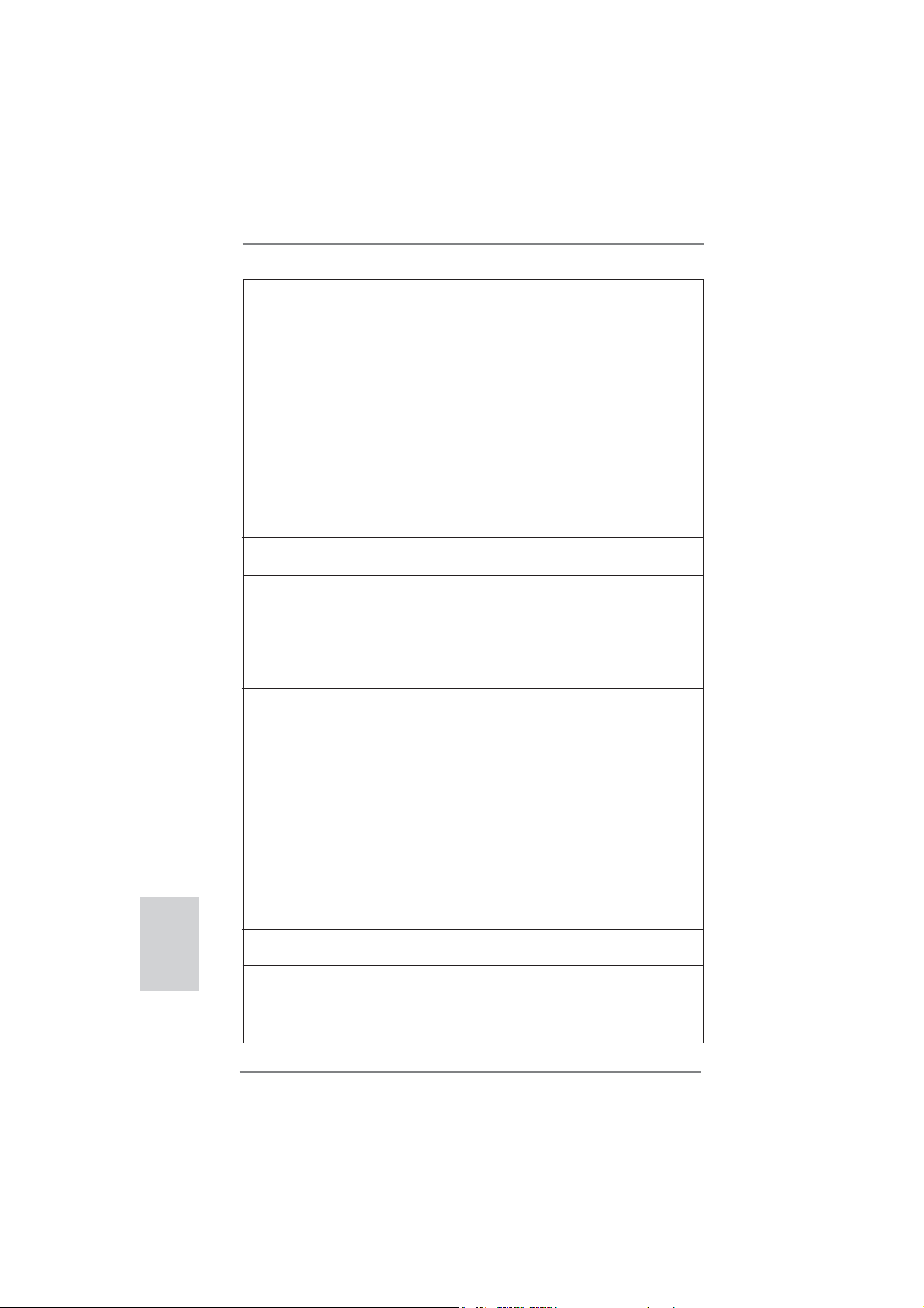
Audio - 7.1 CH HD Audio (Realtek ALC887 Audio Codec)
- Supports THX TruStudio
TM
LAN - PCIE x1 Gigabit LAN 10/100/1000 Mb/s
- Realtek RTL8111E
- Supports Wake-On-LAN
- Supports LAN Cable Detection
- Supports Energy Effi cient Ethernet 802.3az
- Supports PXE
Rear Panel I/O I/O Panel
- 1 x PS/2 Keyboard Port
- 1 x D-Sub Port
- 1 x DVI-D Port
- 1 x HDMI Port
- 1 x Optical SPDIF Out Port
- 4 x Ready-to-Use USB 2.0 Ports
- 1 x eSATA2 Connector
- 2 x Ready-to-Use USB 3.0 Ports
- 1 x RJ-45 LAN Port with LED (ACT/LINK LED and SPEED
LED)
- HD Audio Jack: Rear Speaker/Central/Bass/Line in/Front
Speaker/Microphone (see CAUTION 7)
USB 3.0 - 2 x USB 3.0 ports by ASMedia ASM1042, support
USB 1.0/2.0/3.0 up to 5Gb/s
Connector - 3 x SATA2 3.0 Gb/s connectors, support NCQ, AHCI and
Hot Plug functions
- 1 x CIR header
- 1 x Power LED header
7
ASRock H61M-ITX Motherboard
English
- CPU/Chassis FAN connector
- 24 pin ATX power connector
- 4 pin 12V power connector
- Front panel audio connector
- 2 x USB 2.0 headers (support 4 USB 2.0 ports)
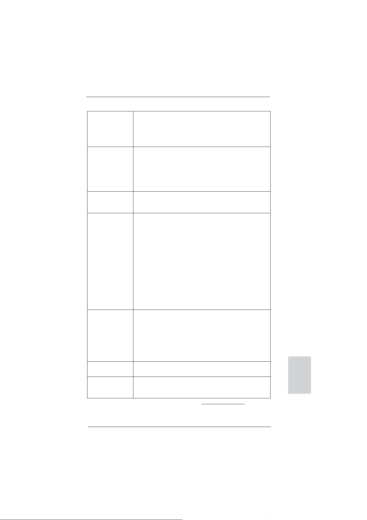
BIOS Feature - 32Mb AMI BIOS
- AMI UEFI Legal BIOS with GUI support
- Supports “Plug and Play”
- ACPI 1.1 Compliance Wake Up Events
- Supports jumperfree
- SMBIOS 2.3.1 Support
Support CD - Drivers, Utilities, AntiVirus Software (Trial Version),
CyberLink MediaEspresso 6.5 Trial, ASRock MAGIX
Multimedia Suite - OEM
Unique Feature - ASRock Extreme Tuning Utility (AXTU) (see CAUTION 8)
- ASRock Instant Boot
- ASRock Instant Flash (see CAUTION 9)
- ASRock APP Charger (see CAUTION 10)
- ASRock SmartView (see CAUTION 11)
- ASRock XFast USB (see CAUTION 12)
- ASRock XFast LAN (see CAUTION 13)
- ASRock XFast RAM (see CAUTION 14)
- ASRock On/Off Play Technology (see CAUTION 15)
- Hybrid Booster:
- ASRock U-COP (see CAUTION 16)
- Boot Failure Guard (B.F.G.)
- Good Night LED
Hardware - CPU Temperature Sensing
Monitor - Chassis Temperature Sensing
- CPU/Chassis Fan Tachometer
- CPU/Chassis Quiet Fan (Allow Chassis Fan Speed
Auto-Adjust by CPU Temperature)
- CPU/Chassis Fan Multi-Speed Control
- Voltage Monitoring: +12V, +5V, +3.3V, CPU Vcore
OS - Microsoft
®
Windows
®
7 / 7 64-bit / Vista
TM
/ Vista
TM
64-bit
/ XP / XP 64-bit compliant
Certifi cations - FCC, CE, WHQL
- ErP/EuP Ready (ErP/EuP ready power supply is required)
(see CAUTION 17)
* For detailed product information, please visit our website: http://www.asrock.com

8
ASRock H61M-ITX Motherboard
English
CAUTION!
1. About the setting of “Hyper Threading Technology”, please check page
40 of “User Manual” in the support CD.
2. This motherboard supports Dual Channel Memory Technology. Before
you implement Dual Channel Memory Technology, make sure to read the
installation guide of memory modules on page 14 for proper installation.
3. Due to the operating system limitation, the actual memory size may be
less than 4GB for the reservation for system usage under Windows
®
7 /
Vista
TM
/ XP. For Windows
®
OS with 64-bit CPU, there is no such limita-
tion. You can use ASRock XFast RAM to utilize the memory that Win-
dows
®
cannot use.
4. The maximum shared memory size is defi ned by the chipset vendor and
is subject to change. Please check Intel
®
website for the latest informa-
tion.
5. You can choose to use two of the four monitors only. D-Sub, DVI-D and
HDMI monitors cannot be enabled at the same time. Besides, with the
DVI-to-HDMI adapter, the DVI-D port can support the same features as
HDMIport.
6. xvYCC is only supported under Windows
®
7 64-bit / 7. HBR is supported
under Windows
®
7 64-bit / 7 / Vista
TM
64-bit / Vista
TM
.
7. For microphone input, this motherboard supports both stereo and mono
modes. For audio output, this motherboard supports 2-channel, 4-chan-
nel, 6-channel, and 8-channel modes. Please check the table on page 3
for proper connection.
8. ASRock Extreme Tuning Utility (AXTU) is an all-in-one tool to fi ne-tune
different system functions in a user-friendly interface, which is including
Hardware Monitor, Fan Control, Overclocking, OC DNA and IES. In
Hardware Monitor, it shows the major readings of your system. In Fan
Control, it shows the fan speed and temperature for you to adjust. In
Overclocking, you are allowed to overclock CPU frequency for optimal
system performance. In OC DNA, you can save your OC settings as a
profi le and share with your friends. Your friends then can load the OC
profi le to their own system to get the same OC settings. In IES (Intelligent
Energy Saver), the voltage regulator can reduce the number of output
WARNING
Please realize that there is a certain risk involved with overclocking, including
adjusting the setting in the BIOS, applying Untied Overclocking Technology, or
using the third-party overclocking tools. Overclocking may affect your system
stability, or even cause damage to the components and devices of your system.
It should be done at your own risk and expense. We are not responsible for possible
damage caused by overclocking.

9
ASRock H61M-ITX Motherboard
English
phases to improve effi ciency when the CPU cores are idle without
sacrificing computing performance. Please visit our website for the
operation procedures of ASRock Extreme Tuning Utility (AXTU).
ASRock website: http://www.asrock.com
9. ASRock Instant Flash is a BIOS fl ash utility embedded in Flash ROM.
This convenient BIOS update tool allows you to update system BIOS
without entering operating systems fi rst like MS-DOS or Windows
®
. With
this utility, you can press <F6> key during the POST or press <F2> key to
BIOS setup menu to access ASRock Instant Flash. Just launch this tool
and save the new BIOS fi le to your USB fl ash drive, fl oppy disk or hard
drive, then you can update your BIOS only in a few clicks without prepar-
ing an additional fl oppy diskette or other complicated fl ash utility. Please
be noted that the USB fl ash drive or hard drive must use FAT32/16/12 fi le
system.
10. If you desire a faster, less restricted way of charging your Apple devices,
such as iPhone/iPod/iPad Touch, ASRock has prepared a wonderful
solution for you - ASRock APP Charger. Simply installing the APP Char-
ger driver, it makes your iPhone charged much quickly from your com-
puter and up to 40% faster than before. ASRock APP Charger allows you
to quickly charge many Apple devices simultaneously and even supports
continuous charging when your PC enters into Standby mode (S1), Sus-
pend to RAM (S3), hibernation mode (S4) or power off (S5). With APP
Charger driver installed, you can easily enjoy the marvelous charging
experience than ever.
ASRock website: http://www.asrock.com/Feature/AppCharger/index.asp
11.
SmartView, a new function of internet browser, is the smart start page for
IE that combines your most visited web sites, your history, your Facebook
friends and your real-time newsfeed into an enhanced view for a more
personal Internet experience. ASRock motherboards are exclusively
equipped with the SmartView utility that helps you keep in touch with
friends on-the-go. To use SmartView feature, please make sure your
OS version is Windows
®
7 / 7 64 bit / Vista
TM
/ Vista
TM
64 bit, and your
browser version is IE8. ASRock website: http://www.asrock.com/Feature/
SmartView/index.asp
12. ASRock XFast USB can boost USB storage device performance. The
performance may depend on the property of the device.
13. ASRock XFast LAN provides a faster internet access, which includes
below benefits. LAN Application Prioritization: You can configure your
application priority ideally and/or add new programs. Lower Latency in
Game: After setting online game priority higher, it can lower the latency in
game. Traffi c Shaping: You can watch Youtube HD video and download
fi les simultaneously. Real-Time Analysis of Your Data: With the status
window, you can easily recognize which data streams you are currently
transferring.

10
ASRock H61M-ITX Motherboard
English
14. ASRock XFast RAM is a new function that is included into ASRock Ex-
treme Tuning Utility (AXTU). It fully utilizes the memory space that cannot
be used under Windows
®
OS 32-bit CPU. ASRock XFast RAM shortens
the loading time of previously visited websites, making web surfi ng faster
than ever. And it also boosts the speed of Adobe Photoshop 5 times
faster. Another advantage of ASRock XFast RAM is that it reduces the
frequency of accessing your SSDs or HDDs in order to extend their lifes-
pan.
15. ASRock On/Off Play Technology allows users to enjoy the great audio ex-
perience from the portable audio devices, such like MP3 player or mobile
phone to your PC, even when the PC is turned off (or in ACPI S5 mode)!
This motherboard also provides a free 3.5mm audio cable (optional) that
ensures users the most convenient computing environment.
16. While CPU overheat is detected, the system will automatically shutdown.
Before you resume the system, please check if the CPU fan on the
motherboard functions properly and unplug the power cord, then plug it
back again. To improve heat dissipation, remember to spray thermal
grease between the CPU and the heatsink when you install the PC sys-
tem.
17. EuP, stands for Energy Using Product, was a provision regulated by Eu-
ropean Union to defi ne the power consumption for the completed system.
According to EuP, the total AC power of the completed system shall be
under 1.00W in off mode condition. To meet EuP standard, an EuP ready
motherboard and an EuP ready power supply are required. According to
Intel’s suggestion, the EuP ready power supply must meet the standard
of 5v standby power effi ciency is higher than 50% under 100 mA current
consumption. For EuP ready power supply selection, we recommend you
checking with the power supply manufacturer for more details.
11
ASRock H61M-ITX Motherboard
English
2. Installation
Pre-installation Precautions
Take note of the following precautions before you install mother-
board components or change any motherboard settings.
1. Unplug the power cord from the wall socket before touching any
component. Failure to do so may cause severe damage to the
motherboard, peripherals, and/or components.
2. To avoid damaging the motherboard components due to static
electricity, NEVER place your motherboard directly on the car-
pet or the like. Also remember to use a grounded wrist strap or
touch a safety grounded object before you handle components.
3. Hold components by the edges and do not touch the ICs.
4. Whenever you uninstall any component, place it on a grounded
antstatic pad or in the bag that comes with the component.
5. When placing screws into the screw holes to secure the moth-
erboard to the chassis, please do not over-tighten the screws!
Doing so may damage the motherboard.
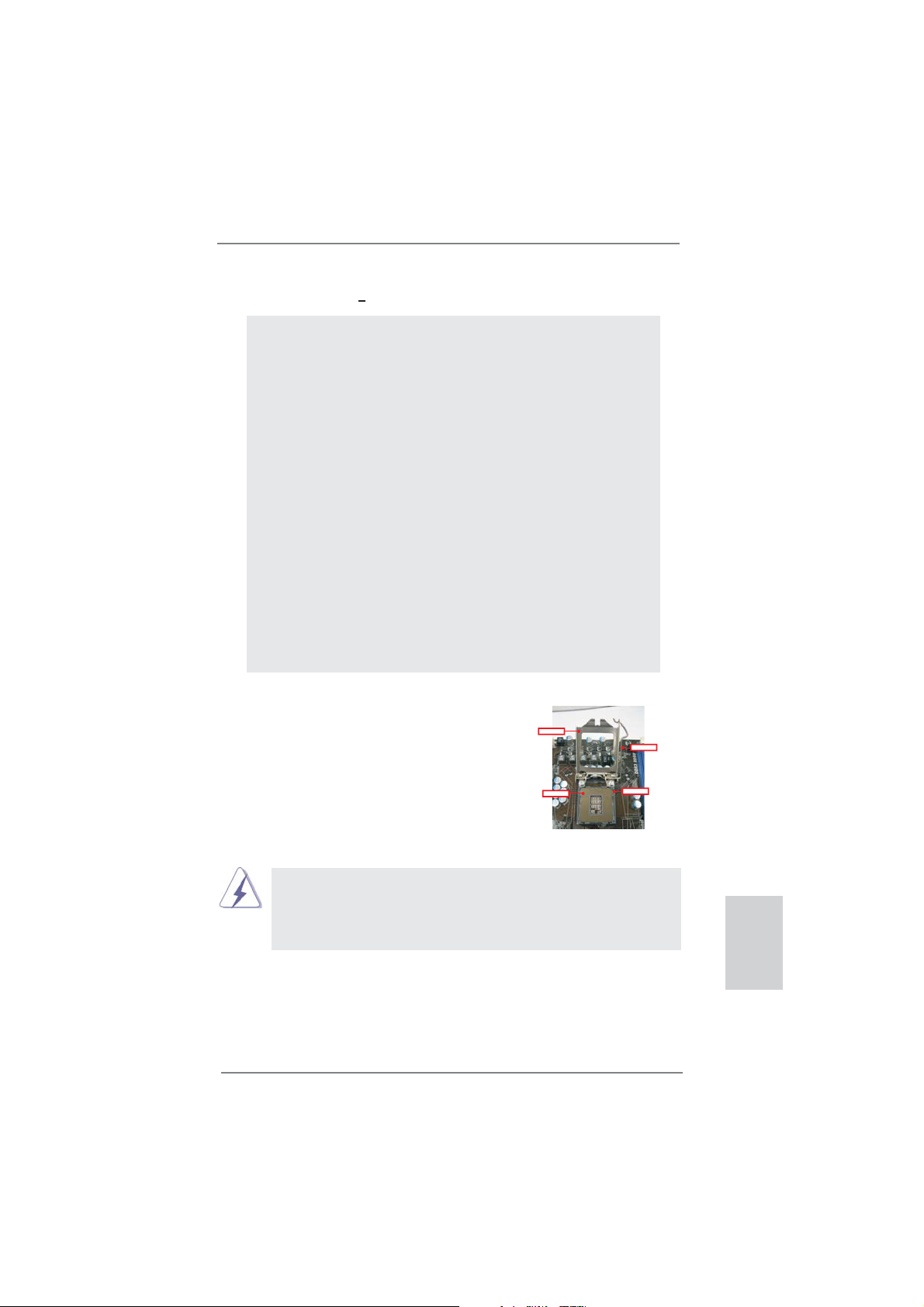
2.1 CPU Installation
For the installation of Intel 1155-Pin CPU,
please follow the steps below.
Before you insert the 1155-Pin CPU into the socket, please check if the
CPU surface is unclean or if there is any bent pin on the socket. Do not
force to insert the CPU into the socket if above situation is found. Other-
wise, the CPU will be seriously damaged.
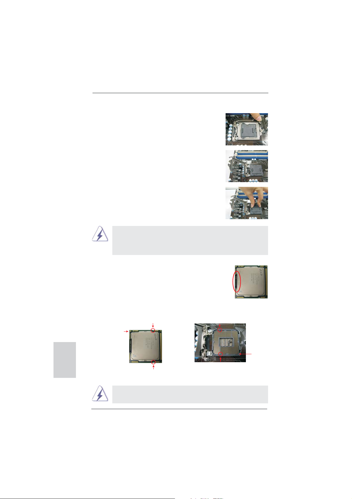
1155-Pin Socket Overview
ContactArray
SocketBody
LoadLever
LoadPlate
12
ASRock H61M-ITX Motherboard
Step 1. Open the socket:
Step 1-1. Disengaging the lever by depressing
down and out on the hook to clear
retention tab.
Step 1-2. Rotate the load lever to fully open po-
sition at approximately 135 degrees.
Step 1-3. Rotate the load plate to fully open po-
sition at approximately 100 degrees.
Step 2. Remove PnP Cap (Pick and Place Cap).
1. It is recommended to use the cap tab to handle and avoid kicking
off the PnP cap.
2. This cap must be placed if returning the motherboard for after
service.
Step 3. Insert the 1155-Pin CPU:
Step 3-1. Hold the CPU by the edges where
are marked with black lines.
Step 3-2. Orient the CPU with IHS (Integrated
Heat Sink) up. Locate Pin1 and the
two orientation key notches.
For proper inserting, please ensure to match the two orientation key
notches of the CPU with the two alignment keys of the socket.
black line
Pin1
alignment key
alignment key
Pin1
1155-Pin CPU
1155-Pin Socket
orientation key notch
orientation key notch
English
13
ASRock H61M-ITX Motherboard
English
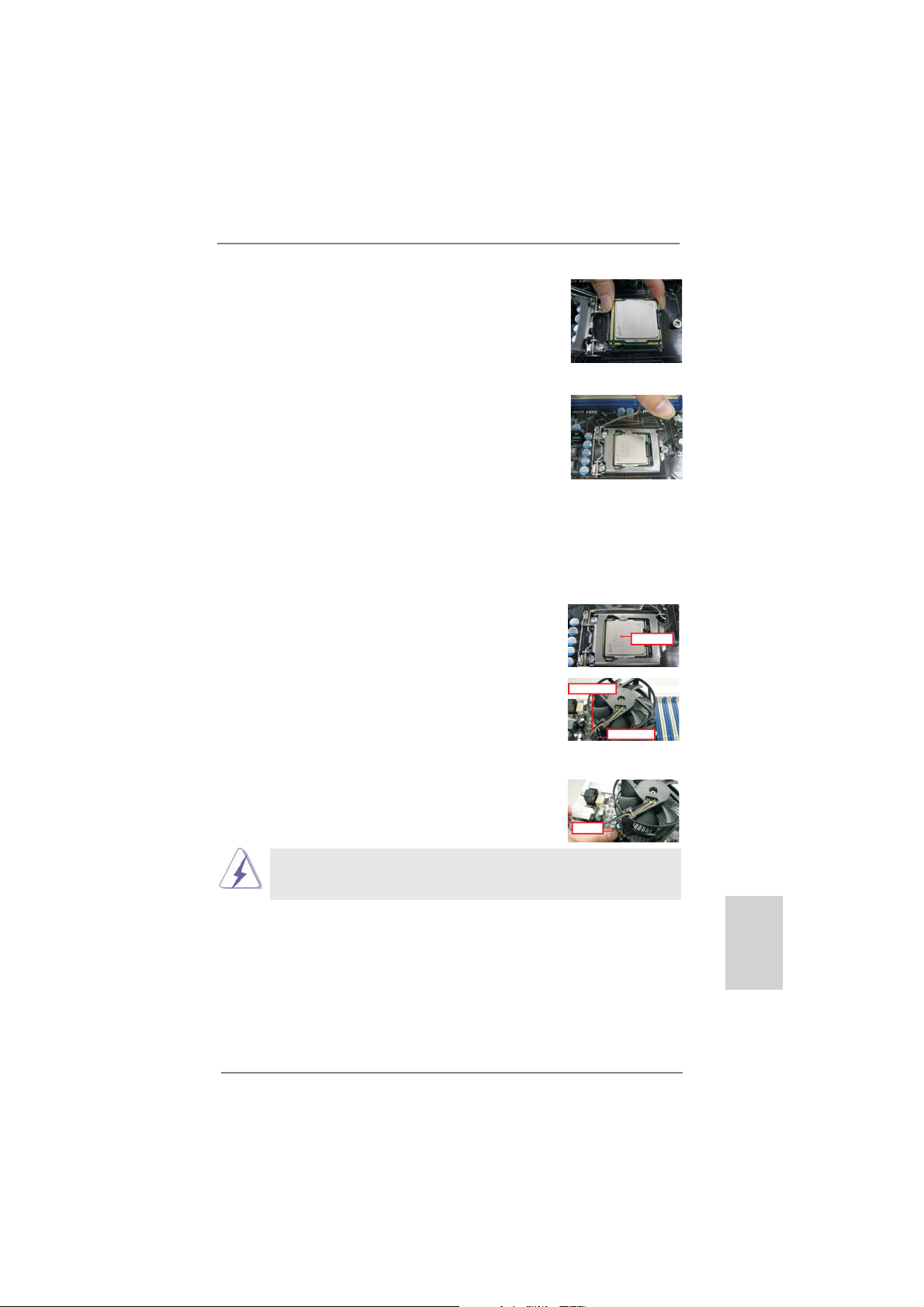
Step 3-3. Carefully place the CPU into the
socket by using a purely vertical mo-
tion.
Step 3-4. Verify that the CPU is within the sock-
et and properly mated to the orient
keys.
Step 4. Close the socket:
Step 4-1. Rotate the load plate onto the IHS.
Step 4-2. While pressing down lightly on load
plate, engage the load lever.
2.2 Installation of CPU Fan and Heatsink
For proper installation, please kindly refer to the instruction manuals of your CPU
fan and heatsink.
Below is an example to illustrate the installation of the heatsink for 1155-Pin CPU.
Step 1. Apply thermal interface material onto center of
IHS on the socket surface.
Step 2. Place the heatsink onto the socket. Ensure
fan cables are oriented on side closest to the
CPU fan connector on the motherboard (CPU_
FAN1, see page 2, No. 17).
Step 3. Align fasteners with the motherboard through-
holes.
Step 4. Rotate the fastener clockwise, then press
down on fastener caps with thumb to install
and lock. Repeat with remaining fasteners.
If you press down the fasteners without rotating them clockwise, the
heatsink cannot be secured on the motherboard.
Step 5. Connect fan header with the CPU fan connector on the motherboard.
Step 6. Secure excess cable with tie-wrap to ensure cable does not interfere with
fan operation or contact other components.
ApplyThermal
InterfaceMaterial
Fancables on side
closestto MB header
Fastenerslots
pointingstraight out
PressDown
(4Places)
14
ASRock H61M-ITX Motherboard
2.3 Installation of Memory Modules (DIMM)
This motherboard provides two 240-pin DDR3 (Double Data Rate 3) DIMM slots,
and supports Dual Channel Memory Technology. For dual channel configuration,
you always need to install two identical (the same brand, speed, size and chip-
type) memory modules in the DDR3 DIMM slots to activate Dual Channel Memory
Technology. Otherwise, it will operate at single channel mode.
1. It is not allowed to install a DDR or DDR2 memory module into
DDR3 slot;otherwise, this motherboard and DIMM may be
damaged.
2. If you install only one memory module or two non-identical
memory modules, it is unable to activate the Dual Channel
Memory Technology.
3. Some DDR3 1GB double-sided DIMMs with 16 chips may not
work on this motherboard. It is not recommended to install them
on this motherboard.
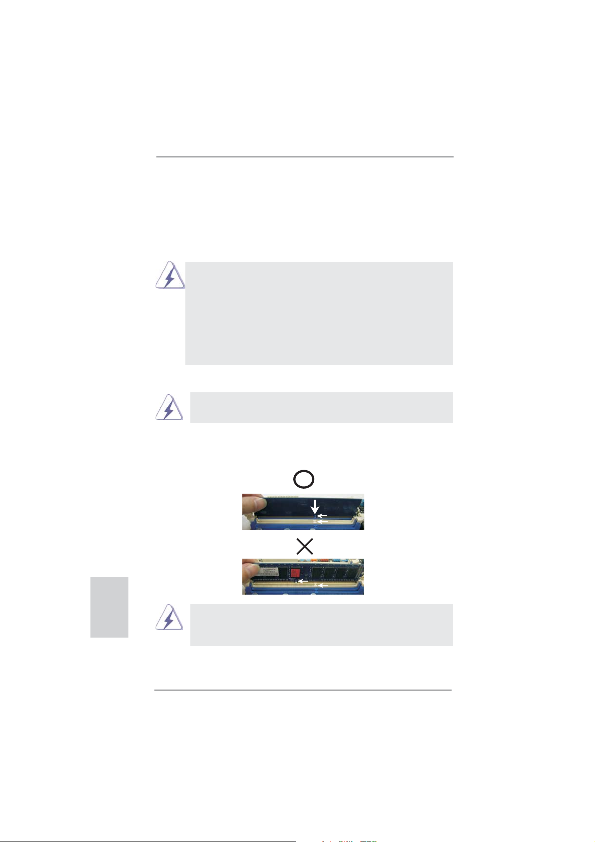
notch
break
notch
break
Installing a DIMM
Please make sure to disconnect power supply before adding or
removing DIMMs or the system components.
Step 1. Unlock a DIMM slot by pressing the retaining clips outward.
Step 2. Align a DIMM on the slot such that the notch on the DIMM matches the
break on the slot.
The DIMM only fi ts in one correct orientation. It will cause permanent
damage to the motherboard and the DIMM if you force the DIMM into the slot
at incorrect orientation.
Step 3. Firmly insert the DIMM into the slot until the retaining clips at both ends
fully snap back in place and the DIMM is properly seated.
English
15
ASRock H61M-ITX Motherboard
English
2.4 Expansion Slot (PCI Express Slot)
There is 1 PCI Express slot on this motherboard.
PCIE slots:
PCIE1 (PCIE 3.0 x16 slot; Blue) is used for PCI Express x16 lane width
graphics cards.
Only PCIE1 slot supports Gen 3 speed. To run the PCI Express in Gen
3 speed, please install an Ivy Bridge CPU. If you install a Sandy Bridge
CPU, the PCI Express will run only at PCI Express Gen 2 speed.
Installing an expansion card
Step 1. Before installing the expansion card, please make sure that the power
supply is switched off or the power cord is unplugged. Please read the
documentation of the expansion card and make necessary hardware
settings for the card before you start the installation.
Step 2. Remove the system unit cover (if your motherboard is already installed
in a chassis).
Step 3. Remove the bracket facing the slot that you intend to use. Keep the
screws for later use.
Step 4. Align the card connector with the slot and press fi rmly until the card is
completely seated on the slot.
Step 5. Fasten the card to the chassis with screws.
Step 6. Replace the system cover.
16
ASRock H61M-ITX Motherboard
English
HDMI port
2. If you have installed onboard VGA driver from our support CD to your system
already, you can freely enjoy the benefi ts of dual monitor function after your
system boots. If you haven’t installed onboard VGA driver yet, please install
onboard VGA driver from our support CD to your system and restart your
computer.
2.5 Dual Monitor and Surround Display Features
Dual Monitor Feature
This motherboard supports dual monitor feature. With the internal VGA output sup-
port (DVI-D, D-Sub and HDMI), you can easily enjoy the benefi ts of dual monitor
feature without installing any add-on VGA card to this motherboard. This mother-
board also provides independent display controllers for DVI-D, D-Sub and HDMI to
support dual VGA output so that DVI-D, D-sub and HDMI can drive same or different
display contents.
To enable dual monitor feature, please follow the below steps:
1. Connect DVI-D monitor cable to DVI-D port on the I/O panel, connect D-Sub
monitor cable to D-Sub port on the I/O panel, or connect HDMI monitor
cable to HDMI port on the I/O panel.
D-Sub port
DVI-D port
D-Sub, DVI-D and HDMI monitors cannot be enabled at the same time.
You can only choose the combination: DVI-D + HDMI, DVI-D + D-Sub,
or HDMI + D-Sub.

17
ASRock H61M-ITX Motherboard
English
Surround Display Feature
This motherboard supports surround display upgrade. With the internal VGA output
support (DVI-D, D-Sub and HDMI) and external add-on PCI Express VGA cards,
you can easily enjoy the benefi ts of surround display feature.
Please refer to the following steps to set up a surround display environment:
1. Install the PCI Express VGA card on PCIE1 slot. Please refer to page 15 for
proper expansion card installation procedures for details.
2. Connect DVI-D monitor cable to DVI-D port on the I/O panel, connect D-Sub
monitor cable to D-Sub port on the I/O panel, or connect HDMI monitor
cable to HDMI port on the I/O panel. Then connect other monitor cables to the
corresponding connectors of the add-on PCI Express VGA card on PCIE1 slot.
3. Boot your system. Press <F2> or <Del> to enter UEFI setup. Enter “Share
Memory” option to adjust the memory capability to [32MB], [64MB], [128MB],
[256MB] or [512MB] to enable the function of D-sub. Please make sure that
the value you select is less than the total capability of the system memory. If you
do not adjust the UEFI setup, the default value of “Share Memory”, [Auto], will
disable D-Sub function when the add-on VGA card is inserted to this
motherboard.
4. Install the onboard VGA driver and the add-on PCI Express VGA card driver to
your system. If you have installed the drivers already, there is no need to install
them again.
5. Set up a multi-monitor display.
For Windows
®
XP / XP 64-bit OS:
Right click the desktop, choose “Properties”, and select the “Settings” tab
so that you can adjust the parameters of the multi-monitor according to
the steps below.
A. Click the “Identify” button to display a large number on each monitor.
B. Right-click the display icon in the Display Properties dialog that you
wish to be your primary monitor, and then select “Primary”. When
you use multiple monitors with your card, one monitor will always be
Primary, and all additional monitors will be designated as Secondary.
C. Select the display icon identifi ed by the number 2.
D. Click “Extend my Windows desktop onto this monitor”.
E. Right-click the display icon and select “Attached”, if necessary.
F. Set the “Screen Resolution” and “Color Quality” as appropriate for the
second monitor. Click “Apply” or “OK” to apply these new values.
G. Repeat steps C through E for the diaplay icon identifi ed by the number
one, two, three and four.

18
ASRock H61M-ITX Motherboard
English
For Windows
®
7 / 7 64-bit / Vista
TM
/ Vista
TM
64-bit OS:
Right click the desktop, choose “Personalize”, and select the “Display
Settings” tab so that you can adjust the parameters of the multi-monitor
according to the steps below.
A. Click the number ”2” icon.
B. Click the items “This is my main monitor” and “Extend the desktop onto
this monitor”.
C. Click “OK” to save your change.
D. Repeat steps A through C for the display icon identifi ed by the number
three and four.
6. Use Surround Display. Click and drag the display icons to positions representing
the physical setup of your monitors that you would like to use. The placement
of display icons determines how you move items from one monitor to another.
HDCP Function
HDCP function is supported on this motherboard. To use HDCP
function with this motherboard, you need to adopt the monitor
that supports HDCP function as well. Therefore, you can enjoy
the superior display quality with high-defi nition HDCP
encryption contents. Please refer to below instruction for more
details about HDCP function.
What is HDCP?
HDCP stands for High-Bandwidth Digital Content Protection,
a specifi cation developed by Intel
®
for protecting digital
entertainment content that uses the DVI interface. HDCP is a
copy protection scheme to eliminate the possibility of
intercepting digital data midstream between the video source,
or transmitter - such as a computer, DVD player or set-top box -
and the digital display, or receiver - such as a monitor, television
or projector. In other words, HDCP specifi cation is designed to
protect the integrity of content as it is being transmitted.
Products compatible with the HDCP scheme such as DVD
players, satellite and cable HDTV set-top-boxes, as well as few
entertainment PCs requires a secure connection to a compliant
display. Due to the increase in manufacturers employing HDCP
in their equipment, it is highly recommended that the HDTV or
LCD monitor you purchase is compatible.
19
ASRock H61M-ITX Motherboard
English
* ASRock Smart Remote is only supported by some of ASRock motherboards. Please refer to
ASRock website for the motherboard support list: http://www.asrock.com
USB 2.0 header (9-pin, blue)
CIR header (4-pin, white)
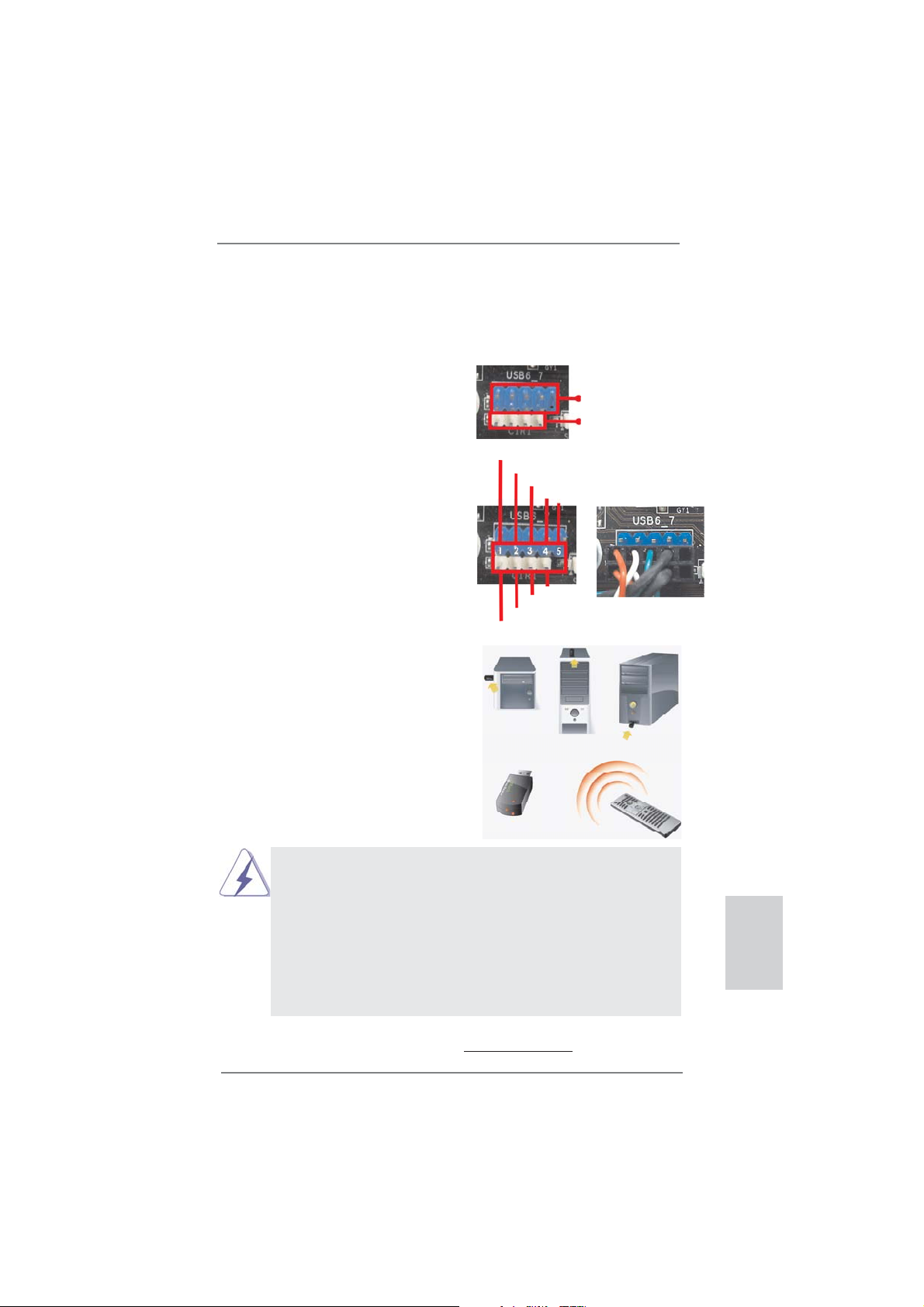
2.6 ASRock Smart Remote Installation Guide
ASRock Smart Remote is only used for ASRock motherboard with CIR header.
Please refer to below procedures for the quick installation and usage of ASRock
Smart Remote.
Step1. Find the CIR header located next
to the USB 2.0 header on ASRock
motherboard.
Step2. Connect the front USB cable to the
USB 2.0 header (as below, pin 1-5)
and the CIR header. Please make
sure the wire assignments and the
pin assignments are matched
correctly.
USB_PWR
P-
P+
GND
ATX+5VSB
IRRX
IRTX
GND
DUMMY
Step3. Install Multi-Angle CIR Receiver to
the front USB port. If Multi-Angle
CIR Receiver cannot successfully
receive the infrared signals from
MCE Remote Controller, please try
to install it to the other front USB
port.
3 CIR sensors in different angles
1. Only one of the front USB port can support CIR function. When
the CIR function is enabled, the other port will remain USB
function.
2. Multi-Angle CIR Receiver is used for front USB only. Please do
not use the rear USB bracket to connect it on the rear panel.
Multi-Angle CIR Receiver can receive the multi-direction infrared
signals (top, down and front), which is compatible with most of
the chassis on the market.
3. The Multi-Angle CIR Receiver
does not support Hot-Plug
function. Please install it before you boot the system.
20
ASRock H61M-ITX Motherboard
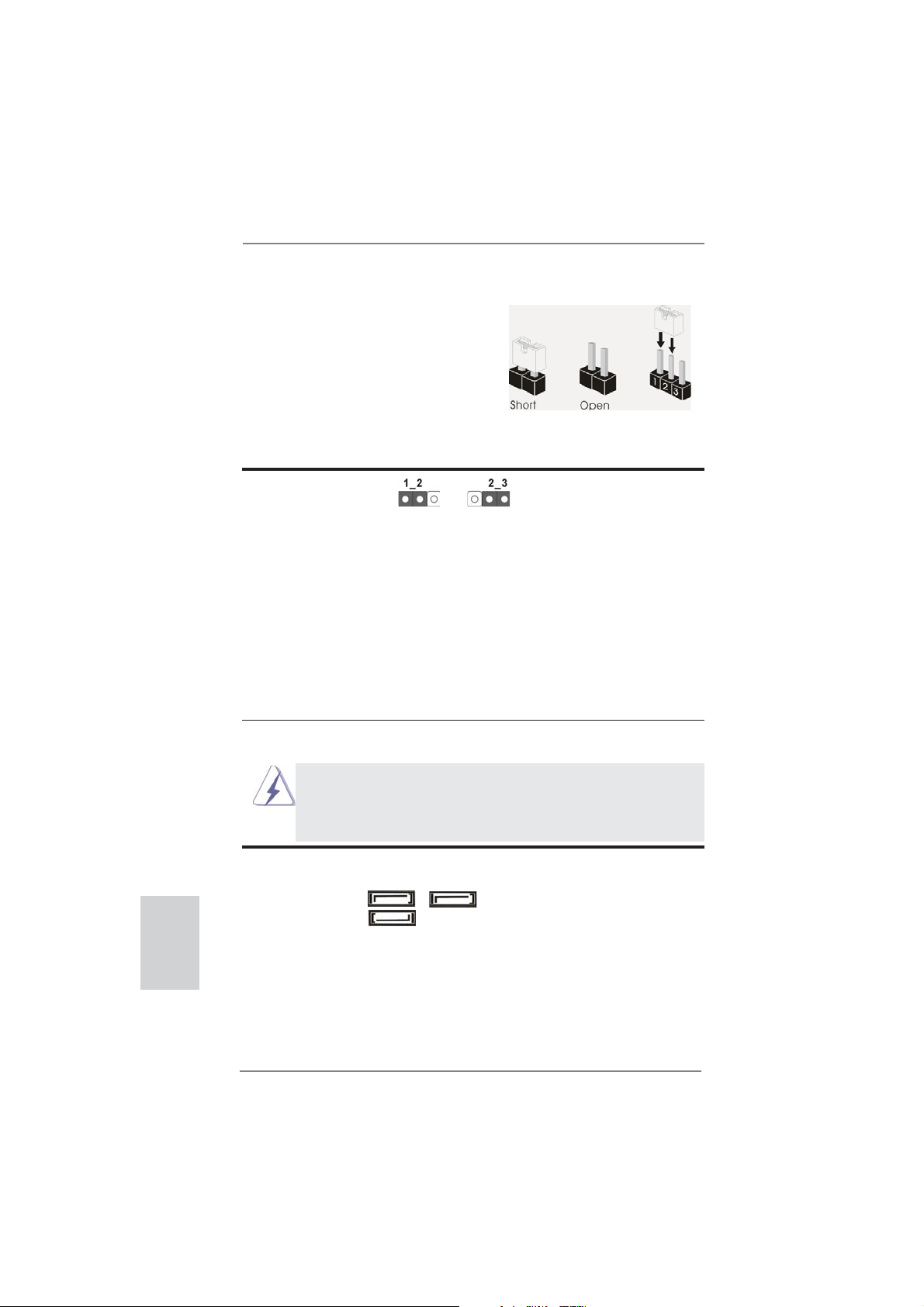
2.7 Jumpers Setup
The illustration shows how jumpers are
setup. When the jumper cap is placed on
pins, the jumper is “Short”. If no jumper cap
is placed on pins, the jumper is “Open”. The
illustration shows a 3-pin jumper whose
pin1 and pin2 are “Short” when jumper cap
is placed on these 2 pins.
Jumper Setting Description
Clear CMOS Jumper
(CLRCMOS1)
(see p.2, No. 5)
Note: CLRCMOS1 allows you to clear the data in CMOS. To clear and reset the
system parameters to default setup, please turn off the computer and unplug
the power cord from the power supply. After waiting for 15 seconds, use a
jumper cap to short pin2 and pin3 on CLRCMOS1 for 5 seconds. However,
please do not clear the CMOS right after you update the BIOS. If you need
to clear the CMOS when you just fi nish updating the BIOS, you must boot up
the system fi rst, and then shut it down before you do the clear-CMOS action.
Please be noted that the password, date, time and user default profi le will be
cleared only if the CMOS battery is removed.
Clear CMOSDefault
English
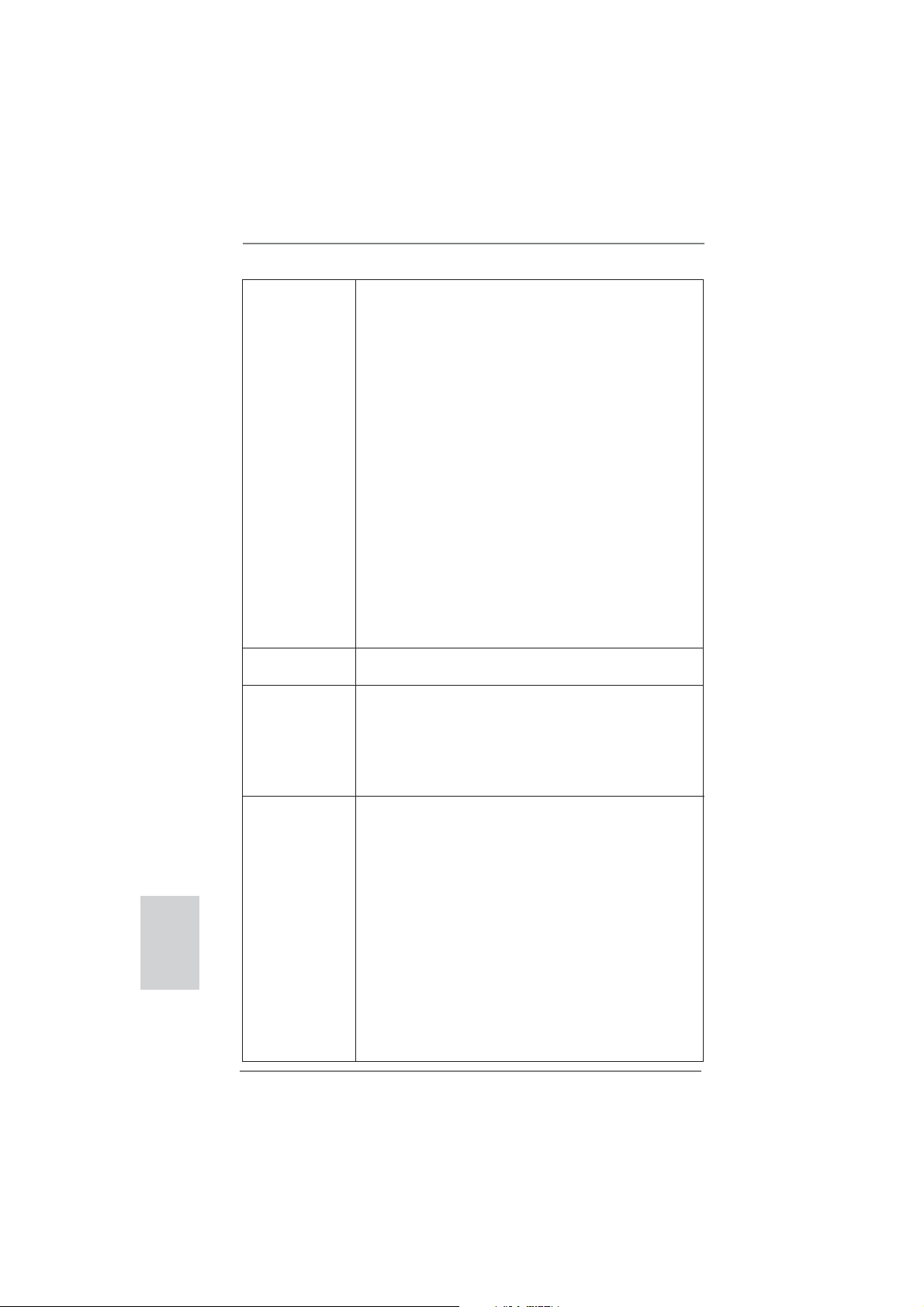
2.8 Onboard Headers and Connectors
Onboard headers and connectors are NOT jumpers. Do NOT place
jumper caps over these headers and connectors. Placing jumper caps
over the headers and connectors will cause permanent damage of the
motherboard!
Serial ATAII Connectors These three Serial ATAII
(SATA_0 (PORT 0):
(SATAII) connectors support
see p.2, No. 3)
SATA data cables for internal
(SATA_1 (PORT 1):
storage devices. The current
see p.2, No. 2)
SATAII interface allows up to
(SATA_2 (PORT 4):
3.0 Gb/s data transfer rate.
see p.2, No. 4)
SATA_1 (PORT 1)
SATA_0 (PORT 0) SATA_2 (PORT 4)
21
ASRock H61M-ITX Motherboard
English
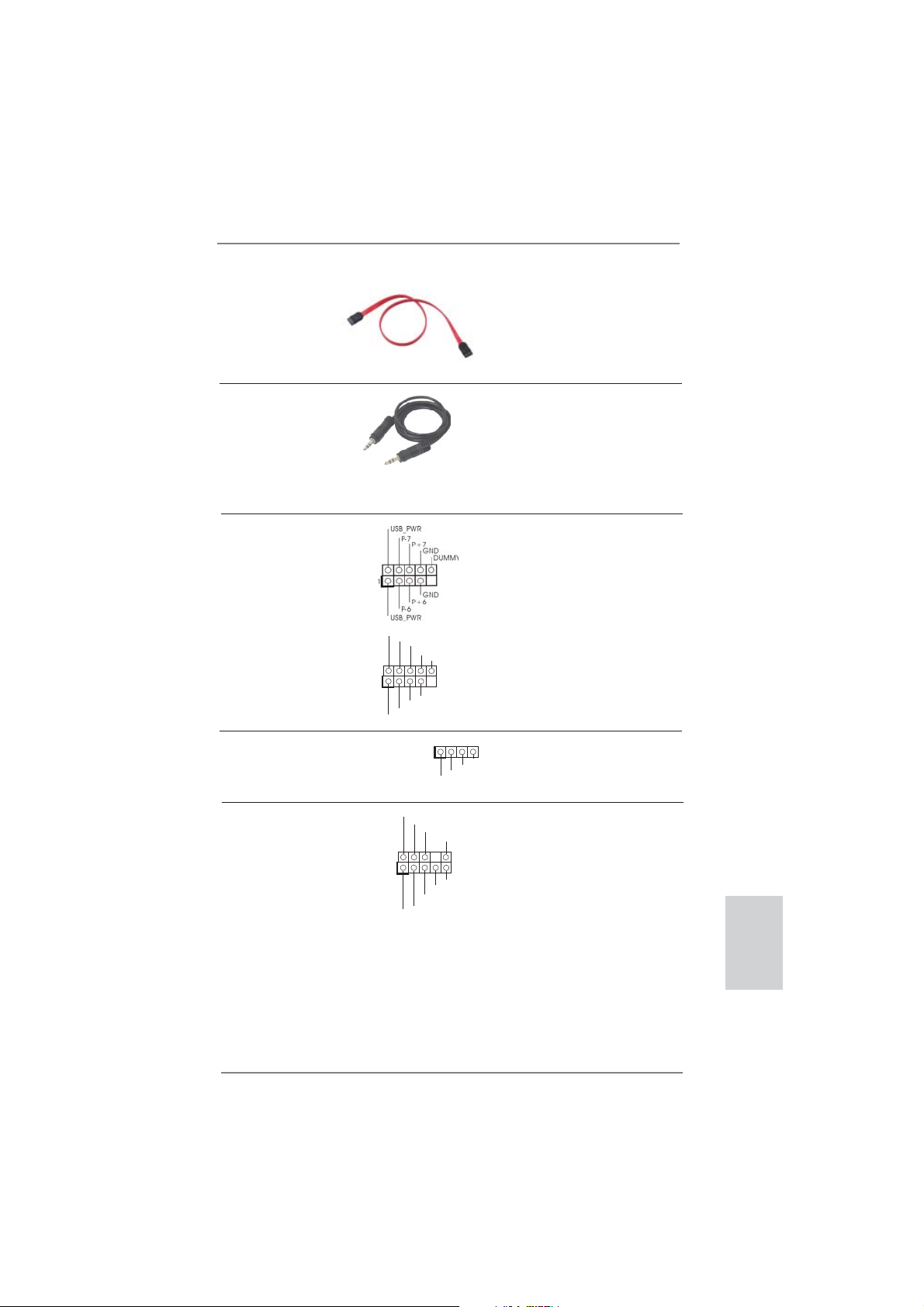
USB 2.0 Headers Besides four default USB 2.0
(9-pin USB6_7)
ports on the I/O panel, there
(see p.2 No. 10)
are two USB 2.0 headers on
this motherboard. Each
USB 2.0 header can support
two USB 2.0 ports.
(9-pin USB8_9)
(see p.2 No. 8)
1
USB_PWR
P-8
GND
DUMMY
USB_PWR
P+8
GND
P-9
P+9
Consumer Infrared Module Header This header can be used to
(4-pin CIR1)
connect the remote
(see p.2 No. 9)
controller receiver.
1
ATX+5VSB
IRTX
GND
IRRX
Serial ATA (SATA) Either end of the SATA data
Data Cable cable can be connected to the
(Optional)
SATA / SATAII hard disk or the
SATAII connector on this
motherboard.
J_SENSE
OUT2_L
1
MIC_RET
PRESENCE#
GND
OUT2_R
MIC2_R
MIC2_L
OUT_RET
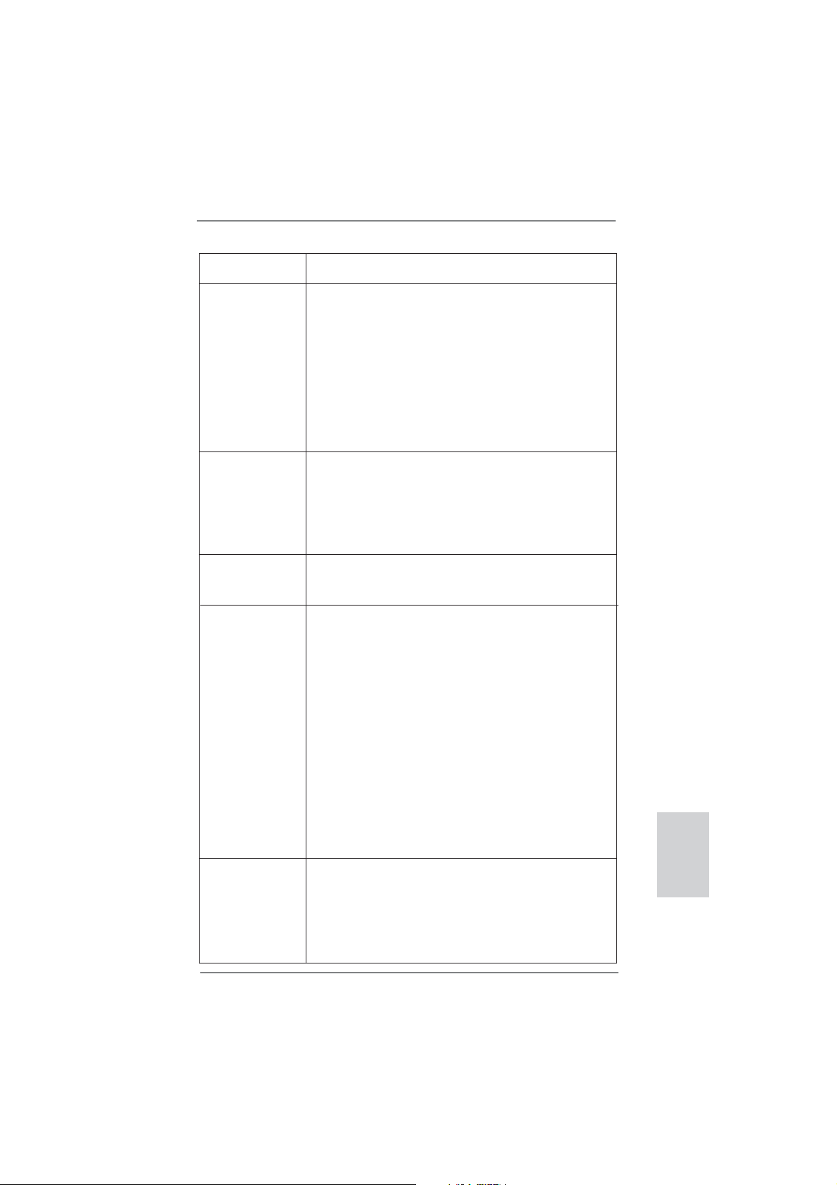
Front Panel Audio Header This is an interface for front
(9-pin HD_AUDIO1)
panel audio cable that allows
(see p.2 No. 14)
convenient connection and
control of audio devices.
3.5mm Audio Cable Either end of the 3.5mm audio
(Optional)
cable can be connected to the
portable audio devices, such
as MP3 player and mobile
phone or the Line-in port of
your PC.
22
ASRock H61M-ITX Motherboard
English
1. High Defi nition Audio supports Jack Sensing, but the panel wire on
the chassis must support HDA to function correctly. Please follow the
instruction in our manual and chassis manual to install your system.
2. If you use AC’97 audio panel, please install it to the front panel audio
header as below:
A. Connect Mic_IN (MIC) to MIC2_L.
B. Connect Audio_R (RIN) to OUT2_R and Audio_L (LIN) to OUT2_L.
C. Connect Ground (GND) to Ground (GND).
D. MIC_RET and OUT_RET are for HD audio panel only. You don’t
need to connect them for AC’97 audio panel.
E. To activate the front mic.
For Windows
®
XP / XP 64-bit OS:
Select “Mixer”. Select “Recorder”. Then click “FrontMic”.
For Windows
®
7 / 7 64-bit / Vista
TM
/ Vista
TM
64-bit OS:
Go to the "FrontMic" Tab in the Realtek Control panel. Adjust
“Recording Volume”.
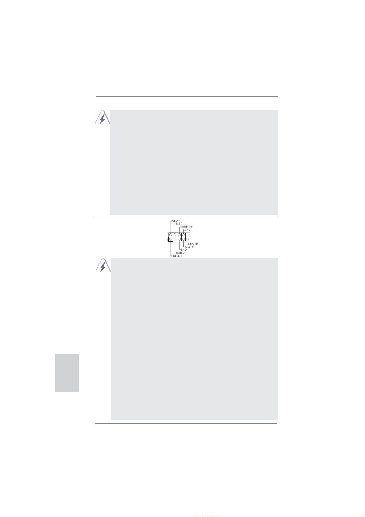
System Panel Header This header accommodates
(9-pin PANEL1)
several system front panel
(see p.2 No. 1)
functions.
Connect the power switch, reset switch and system status indicator on the
chassis to this header according to the pin assignments below. Note the
positive and negative pins before connecting the cables.
PWRBTN (Power Switch):
Connect to the power switch on the chassis front panel. You may confi gure
the way to turn off your system using the power switch.
RESET (Reset Switch):
Connect to the reset switch on the chassis front panel. Press the reset
switch to restart the computer if the computer freezes and fails to perform a
normal restart.
PLED (System Power LED):
Connect to the power status indicator on the chassis front panel. The LED
is on when the system is operating. The LED keeps blinking when the sys-
tem is in S1 sleep state. The LED is off when the system is in S3/S4 sleep
state or powered off (S5).
HDLED (Hard Drive Activity LED):
Connect to the hard drive activity LED on the chassis front panel. The LED
is on when the hard drive is reading or writing data.
The front panel design may differ by chassis. A front panel module mainly
consists of power switch, reset switch, power LED, hard drive activity LED,
speaker and etc. When connecting your chassis front panel module to this
header, make sure the wire assignments and the pin assign-ments are
matched correctly.
23
ASRock H61M-ITX Motherboard
English
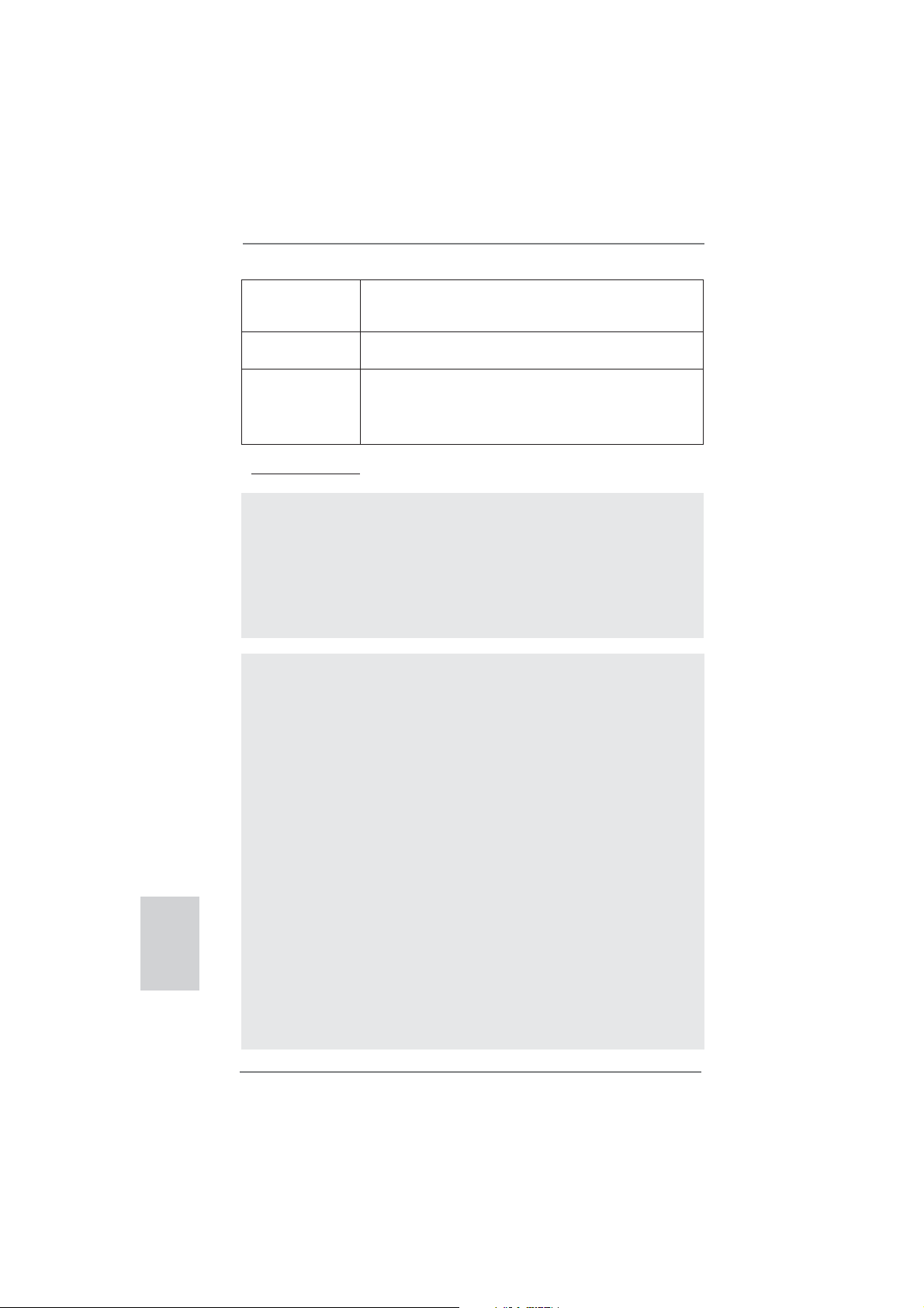
Power LED Header Please connect the chassis
(3-pin PLED1)
power LED to this header to
(see p.2 No. 19)
indicate system power status.
The LED is on when the system
is operating. The LED keeps
blinking in S1 state. The LED is
off in S3/S4 state or S5 state
(power off).
1
PLED+
PLED+
PLED-
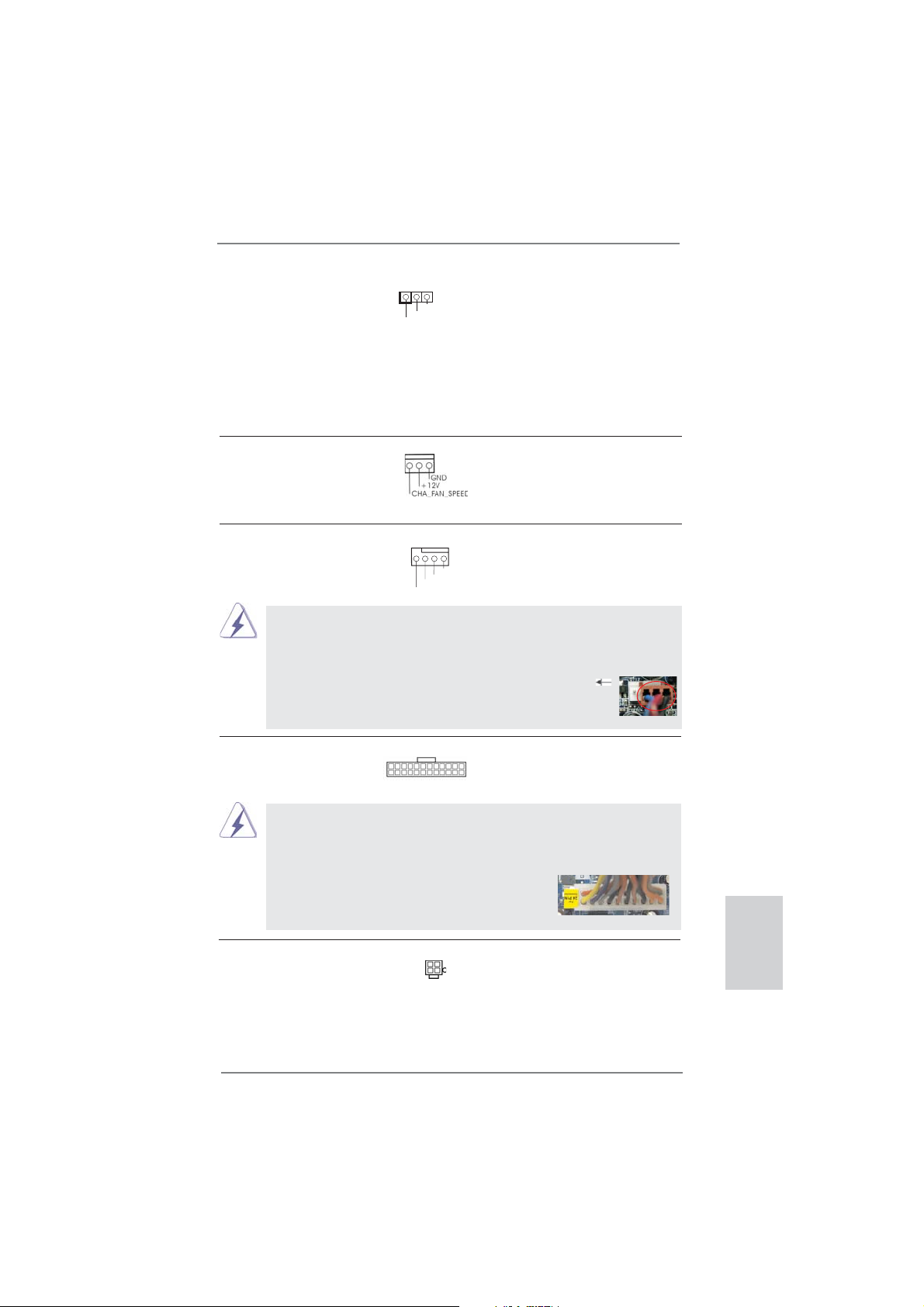
Chassis Fan Connector Please connect the fan cables
(3-pin CHA_FAN1)
to the fan connectors and
(see p.2 No. 18)
match the black wire to the
ground pin.
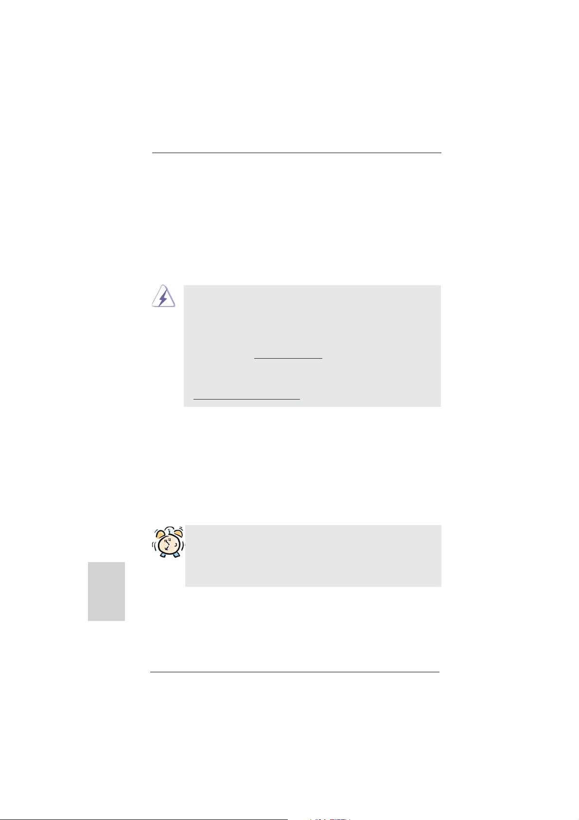
CPU Fan Connectors Please connect the CPU fan
(4-pin CPU_FAN1)
cable to the connector and
(see p.2 No. 17)
match the black wire to the
ground pin.
Though this motherboard provides 4-Pin CPU fan (Quiet Fan) support, the 3-Pin
CPU fan still can work successfully even without the fan speed control function.
If you plan to connect the 3-Pin CPU fan to the CPU fan connector on this
motherboard, please connect it to Pin 1-3.
3-Pin Fan Installation
Pin 1-3 Connected
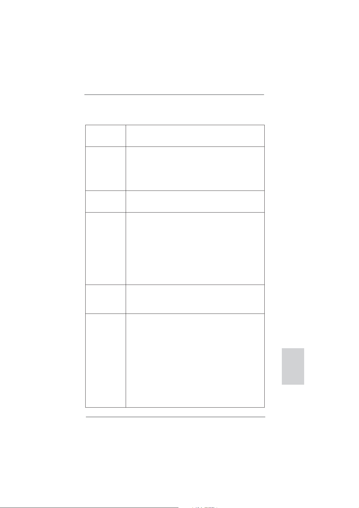
ATX Power Connector Please connect an ATX power
(24-pin ATXPWR1)
supply to this connector.
(see p.2 No. 7)
20-Pin ATX Power Supply Installation
Though this motherboard provides 24-pin ATX power connector, it can still work if
you adopt a traditional 20-pin ATX power supply. To use the 20-pin ATX power
supply, please plug your power supply along with Pin 1 and Pin 13.
ATX 12V Power Connector Please connect an ATX 12V
(4-pin ATX12V1)
power supply to this connector.
(see p.2 No. 15)
12 1
24 13
12 1
24 13
GND
+12V
CPU_FAN_SPEED
FAN_SPEED_CONTROL
4 3 2 1

24
ASRock H61M-ITX Motherboard
English
2.9 Driver Installation Guide
To install the drivers to your system, please insert the support CD to your optical
drive fi rst. Then, the drivers compatible to your system can be auto-detected and
listed on the support CD driver page. Please follow the order from up to bottom side
to install those required drivers. Therefore, the drivers you install can work properly.
2.10 Installing Windows
®
7 / 7 64-bit / Vista
TM
/ Vista
TM
64-bit / XP
/ XP 64-bit Without RAID Functions
If you want to install Windows
®
7 / 7 64-bit / Vista
TM
/ Vista
TM
64-bit / XP / XP 64-
bit OS on your SATA / SATAII HDDs without RAID functions, please follow below
procedures according to the OS you install.
2.10.1 Installing Windows
®
XP / XP 64-bit Without RAID
Functions
If you want to install Windows
®
XP / XP 64-bit OS on your SATA / SATAII HDDs
without RAID functions, please follow below steps.
STEP 1: Set up UEFI.
A. Enter UEFI SETUP UTILITY Advanced screen SATA Confi guration.
B. Set the option “SATA Mode Selection” to [IDE].
STEP 2: Install Windows
®
XP / XP 64-bit OS on your system.
Using SATA / SATAII HDDs without NCQ function
2.10.2 Installing Windows
®
7 / 7 64-bit / Vista
TM
/ Vista
TM
64-bit
Without RAID Functions
If you want to install Windows
®
7 / 7 64-bit / Vista
TM
/ Vista
TM
64-bit OS on your SATA
/ SATAII HDDs without RAID functions, please follow below steps.
Using SATA / SATAII HDDs with NCQ function
STEP 1: Set Up UEFI.
A. Enter UEFI SETUP UTILITY Advanced screen SATA Confi guration.
B. Set the option “SATA Mode Selection” to [AHCI].
STEP 2: Install Windows
®
7 / 7 64-bit / Vista
TM
/ Vista
TM
64-bit OS on your
system.

25
ASRock H61M-ITX Motherboard
English
3. BIOS Information
The Flash Memory on the motherboard stores BIOS Setup Utility. When you start up
the computer, please press <F2> or <Del> during the Power-On-Self-Test (POST)
to enter BIOS Setup utility; otherwise, POST continues with its test routines. If you
wish to enter BIOS Setup after POST, please restart the system by pressing <Ctl>
+ <Alt> + <Delete>, or pressing the reset button on the system chassis. The BIOS
Setup program is designed to be user-friendly. It is a menu-driven program, which
allows you to scroll through its various sub-menus and to select among the prede-
termined choices. For the detailed information about BIOS Setup, please refer to the
User Manual (PDF fi le) contained in the Support CD.
4. Software Support CD information
This motherboard supports various Microsoft
®
Windows
®
operating systems: 7 / 7
64-bit / Vista
TM
/ Vista
TM
64-bit / XP / XP 64-bit. The Support CD that came with the
motherboard contains necessary drivers and useful utilities that will enhance moth-
erboard features. To begin using the Support CD, insert the CD into your CD-ROM
drive. It will display the Main Menu automatically if “AUTORUN” is enabled in your
computer. If the Main Menu does not appear automatically, locate and double-click
on the fi le “ASSETUP.EXE” from the BIN folder in the Support CD to display the
menus.
Using SATA / SATAII HDDs without NCQ function
STEP 1: Set up UEFI.
A. Enter UEFI SETUP UTILITY Advanced screen SATA Confi guration.
B. Set the option “SATA Mode Selection” to [IDE].
STEP 2: Install Windows
®
7 / 7 64-bit / Vista
TM
/ Vista
TM
64-bit OS on your
system.
26
ASRock H61M-ITX Motherboard
1. Einführung
Wir danken Ihnen für den Kauf des ASRock H61M-ITX Motherboard, ein zuver-
lässiges Produkt, welches unter den ständigen, strengen Qualitätskontrollen von
ASRock gefertigt wurde. Es bietet Ihnen exzellente Leistung und robustes Design,
gemäß der Verpflichtung von ASRock zu Qualität und Halbarkeit. Diese Schnel-
linstallationsanleitung führt in das Motherboard und die schrittweise Installation
ein. Details über das Motherboard fi nden Sie in der Bedienungsanleitung auf der
Support-CD.
Da sich Motherboard-Spezifi kationen und BIOS-Software verändern
können, kann der Inhalt dieses Handbuches ebenfalls jederzeit geändert
werden. Für den Fall, dass sich Änderungen an diesem Handbuch
ergeben, wird eine neue Version auf der ASRock-Website, ohne weitere
Ankündigung, verfügbar sein. Die neuesten Grafi kkarten und unterstützten
CPUs sind auch auf der ASRock-Website aufgelistet.
ASRock-Website: http://www.asrock.com
Wenn Sie technische Unterstützung zu Ihrem Motherboard oder spezifi sche
Informationen zu Ihrem Modell benötigen, besuchen Sie bitte unsere
Webseite:
www.asrock.com/support/index.asp
1.1 Kartoninhalt
ASRock H61M-ITX Motherboard
(Mini-ITX-Formfaktor: 17.0 cm x 17.0 cm; 6.7 Zoll x 6.7 Zoll)
ASRock H61M-ITX Schnellinstallationsanleitung
ASRock H61M-ITX Support-CD
Zwei Serial ATA (SATA) -Datenkabel (optional)
Ein Audiokabel (3,5 mm, Klinke) (optional)
Ein I/O Shield
ASRock erinnert...
Zur besseren Leistung unter Windows
®
7 / 7, 64 Bit / Vista
TM
/ Vista
TM
64 Bit empfehlen wir, die Speicherkonfi guration im BIOS auf den AHCI-
Modus einzustellen. Hinweise zu den BIOS-Einstellungen fi nden Sie in
der Bedienungsanleitung auf der mitgelieferten CD.
Deutsch
27
ASRock H61M-ITX Motherboard
Deutsch
1.2 Spezifikationen
Plattform - Mini-ITX-Formfaktor: 17.0 cm x 17.0 cm; 6.7 Zoll x 6.7 Zoll
- Alle Feste Kondensatordesign (100% in Japan gefertigte,
erstklassige leitfähige Polymer-Kondensatoren)
CPU - Unterstützt Intel
®
Core
TM
i7- / i5- / i3-Prozessoren der 3ten
und 2ten Generation im LGA1155-Package
- Unterstützt Intel
®
Turbo Boost 2.0-Technologie
- Unterstützt freigegebene CPU der K-Serie
- Unterstützt Hyper-Threading-Technologie
(siehe VORSICHT 1)
Chipsatz - Intel
®
H61
- Unterstützt Intel
®
Rapid Start Technology und Smart
Connect Technology
Speicher - Unterstützung von Dual-Kanal-Speichertechnologie
(siehe VORSICHT 2)
- 2 x Steckplätze für DDR3
- Unterstützt DDR3 1600/1333/1066 non-ECC, ungepufferter
Speicher (DDR3 1600 mit Intel
®
Ivy Bridge-Prozessor,
DDR3 1333 mit Intel
®
Sandy Bridge-Prozessor)
- Max. Kapazität des Systemspeichers: 16GB
(siehe VORSICHT 3)
- Unterstützt Intel
®
Extreme Memory Profi le (XMP)1.3/1.2 mit
Intel
®
Ivy Bridge-Prozessor
Erweiterungs- - 1 x PCI Express 3.0 x16-Steckplatz (blau für x16-Modus)
steckplätze * PCIE 3.0 wird nur mit Intel
®
Ivy Bridge-Prozessor
unterstützt. Mit Intel
®
Sandy Bridge-Prozessor wird nur
PCIE 2.0 unterstützt.
Onboard-VGA * Integrierte Intel
®
HD-Grafi kdarstellungen und die VGA-
Ausgänge können nur durch GPU-integrierte Prozessoren
unterstützt werden.
- Unterstützt hochaufl ösende integrierte Intel
®
-Grafi klösungen:
Intel
®
Quick-Sync-Video 2.0, Intel
®
InTru
TM
3D, Intel
®
Clear-
Video-Technik (HD), Intel
®
Insider
TM
, Intel
®
HD Graphics
2500/4000 mit Intel
®
Ivy Bridge-Prozessor
- Unterstützt hochaufl ösende integrierte Intel
®
-Grafi klösungen:
Intel
®
Quick-Sync-Video, Intel
®
InTru
TM
3D, Intel
®
Clear-
Video-Technik (HD), Intel
®
HD Graphics 2000/3000, Intel
®
Advanced Vector Extensions (AVX) mit Intel
®
Sandy Bridge-
Prozessor
- Pixel Shader 5.0, DirectX 11 mit Intel
®
Ivy Bridge-Prozessor,
28
ASRock H61M-ITX Motherboard
Pixel Shader 4.1, DirectX 10.1 mit Intel
®
Sandy Bridge-
Prozessor
- Maximal gemeinsam genutzter Speicher 1760MB mit Intel
®
Ivy Bridge-Prozessor. Maximal gemeinsam genutzter
Speicher 1759MB mit Intel
®
Sandy Bridge-Prozessor.
(siehe VORSICHT 4)
- Drei VGA-Ausgangsoptionen: D-Sub, DVI-D sowie HDMI
(siehe VORSICHT 5)
- Unterstützt HDMI 1.4a mit einer maximalen Aufl ösung von
1920 x 1200 bei 60 Hz
- Unterstützt DVI mit einer maximalen Aufl ösung von
1920 x 1200 bei 60 Hz
- Unterstützt D-Sub mit einer maximalen Aufl ösung von
2048 x 1536 bei 75 Hz
- Unterstützt Auto Lip Sync, xvYCC und HBR (High Bit
Rate-Audio) mit HDMI (kompatibler HDMI-Bildschirm
erforderlich) (siehe VORSICHT 6)
- Unterstützt HDCP-Funktion mit DVI- und HDMI-Ports
- Unterstutzt 1080p Blu-ray (BD) / HD-DVD-Wiedergabe mit
DVI- und HDMI-Ports
Audio - 7.1
CH HD Audio (Realtek ALC887 Audio Codec)
- Unterstützt THX TruStudio
TM
LAN - PCIE x1 Gigabit LAN 10/100/1000 Mb/s
- Realtek RTL8111E
- Unterstützt Wake-On-LAN
- Unterstützt LAN-Kabelerkennung
- Unterstützt energieeffi zientes Ethernet 802.3az
- Unterstützt PXE
E/A-Anschlüsse I/O Panel
an der - 1 x PS/2-Tastaturanschluss
Rückseite - 1 x D-Sub port
- 1 x DVI-D port
- 1 x HDMI port
- 1 x optischer SPDIF-Ausgang
- 4 x Standard-USB 2.0-Anschlüsse
- 1 x eSATA2-Anschluss
- 2 x Standard-USB 3.0-Anschlüsse
- 1 x RJ-45 LAN Port mit LED (ACT/LINK LED und SPEED
LED)
- HD Audiobuchse: Lautsprecher hinten / Mitte/Bass /
Audioeingang / Lautsprecher vorne / Mikrofon
(siehe VORSICHT 7)
Deutsch
29
ASRock H61M-ITX Motherboard
Deutsch
USB3.0 - 2 x USB 3.0-Ports an der Rückseite durch ASMedia
ASM1042, unterstützt USB 1.0/2.0/3.0 mit bis zu 5 Gb/s
Anschlüsse - 3 x SATA2 3,0 GB/s-Anschlüsse, unterstützen NCQ-, AHCI-
und „Hot Plug“ (Hot-Plugging)- Funktionen
- 1 x
Consumer Infrared-Modul-Header
- 1 x Betriebs-LED-Header
- CPU/Gehäuselüfter-Anschluss
- 24-pin ATX-Netz-Header
- 4-pin anschluss für 12V-ATX-Netzteil
- Anschluss für Audio auf der Gehäusevorderseite
- 2 x USB 2.0-Anschlüsse (Unterstützung 4 zusätzlicher
USB 2.0-Anschlüsse)
BIOS - 32Mb AMI BIOS
- AMIs Legal BIOS UEFI mit GUI-Unterstützung
- Unterstützung für “Plug and Play”
- ACPI 1.1-Weckfunktionen
- JumperFree-Übertaktungstechnologie
- SMBIOS 2.3.1
CD d’assistance - Pilotes, utilitaires, logiciel anti-virus (version d’évaluation),
CyberLink MediaEspresso 6.5 Trial, ASRock MAGIX-
Multimedia-Suite - OEM
Einzigartige - ASRock Extreme Tuning Utility (AXTU)
Eigenschaft (siehe VORSICHT 8)
- ASRock Sofortstart
- ASRock Instant Flash (siehe VORSICHT 9)
- ASRock APP Charger (siehe VORSICHT 10)
- ASRock SmartView (siehe VORSICHT 11)
- ASRock XFast USB (siehe VORSICHT 12)
- ASRock XFast LAN (siehe VORSICHT 13)
- ASRock XFast RAM (siehe VORSICHT 14)
- ASRock ein/aus-Wiedergabetechnologie
(siehe VORSICHT 15)
- Hybrid Booster:
- ASRock U-COP (siehe VORSICHT 16)
- Boot Failure Guard (B.F.G. – Systemstartfehlerschutz)
- Gute Nacht-LED
Hardware Monitor - Überwachung der CPU-Temperatur
- Motherboardtemperaturerkennung
- Drehzahlmessung für CPU/Gehäuselüfter
- Geräuscharmer CPU-/Gehäuselüfter (ermöglicht die au
tomatische Anpassung der Gehäuselüftergeschwindigkeit
durch CPU- oder Temperatur)
30
ASRock H61M-ITX Motherboard
VORSICHT!
1. Die Einstellung der “Hyper-Threading Technology”, fi nden Sie auf Seite
40 des auf der Support-CD enthaltenen Benutzerhandbuches beschrie-
ben.
2. Dieses Motherboard unterstützt Dual-Kanal-Speichertechnologie. Vor
Implementierung der Dual-Kanal-Speichertechnologie müssen Sie die
Installationsanleitung für die Speichermodule auf Seite 14 zwecks
richtiger Installation gelesen haben.
3. Durch Betriebssystem-Einschränkungen kann die tatsächliche Speicher-
größe weniger als 4 GB betragen, da unter Windows
®
7 / Vista™ / XP et-
was Speicher zur Nutzung durch das System reserviert wird. Unter Win-
dows
®
OS mit 64-Bit-CPU besteht diese Einschränkung nicht. ASRock
XFast RAM zur Nutzung des Speichers, den Windows
®
nicht verwenden
kann, einsetzen.
4. Die Maximalspeichergröße ist von den Chipshändler defi niert und umge-
tauscht. Bitte überprüfen Sie Intel
®
website für die neuliche Information.
5. Sie können nur die Nutzung von zwei von drei Bildschirmen auswählen.
Die D-Sub-, DVI-D- und HDMI-Bildschirme können nicht gleichzeitig
aktiviert werden. Zudem kann der DVI-D-Port mit DVI-zu-HDMI-Adapter
dieselben Funktionen wie der HDMI-Port unterstützen.
6. xvYCC werden nur unter Windows
®
7 64-Bit / 7 unterstützt. HBR wird
unter Windows
®
7 64 Bit / 7 / Vista
TM
64 Bit / Vista
TM
unterstützt.
Deutsch
- Mehrstufi ge Geschwindigkeitsteuerung für CPU-/
Gehäuselüfter
- Spannungsüberwachung: +12V, +5V, +3.3V, Vcore
Betriebssysteme - Unterstützt Microsoft
®
Windows
®
7 / 7 64-Bit / Vista
TM
/
Vista
TM
64-Bit / XP / XP 64-Bit
Zertifi zierungen - FCC, CE, WHQL
- Gemäß Ökodesign-Richtlinie (ErP/EuP) (Stromversorgung
gemäß Ökodesign-Richtlinie (ErP/EuP) erforderlich)
(siehe VORSICHT 17)
* Für die ausführliche Produktinformation, besuchen Sie bitte unsere Website:
http://www.asrock.com
WARNUNG
Beachten Sie bitte, dass Overclocking, einschließlich der Einstellung im BIOS,
Anwenden der Untied Overclocking-Technologie oder Verwenden von Overclocking-
Werkzeugen von Dritten, mit einem gewissen Risiko behaftet ist. Overclocking kann
sich nachteilig auf die Stabilität Ihres Systems auswirken oder sogar Komponenten
und Geräte Ihres Systems beschädigen. Es geschieht dann auf eigene Gefahr und
auf Ihre Kosten. Wir übernehmen keine Verantwortung für mögliche Schäden, die
aufgrund von Overclocking verursacht wurden.
 Loading...