


H470M-ITX-ac
Table of contents
 Loading...

Version 1.1
Published January 2020
Copyright©2020 ASRock INC. All rights reserved.
Copyright Notice:
No part of this documentation may be reproduced, transcribed, transmitted, or
translated in any language, in any form or by any means, except duplication of
documentation by the purchaser for backup purpose, without written consent of
ASRock Inc.
Products and corporate names appearing in this documentation may or may not
be registered trademarks or copyrights of their respective companies, and are used
only for identication or explanation and to the owners’ benet, without intent to
infringe.
Disclaimer:
Specications and information contained in this documentation are furnished for
informational use only and subject to change without notice, and should not be
constructed as a commitment by ASRock. ASRock assumes no responsibility for
any errors or omissions that may appear in this documentation.
With respect to the contents of this documentation, ASRock does not provide
warranty of any kind, either expressed or implied, including but not limited to
the implied warranties or conditions of merchantability or tness for a particular
purpose.
In no event shall ASRock, its directors, ocers, employees, or agents be liable for
any indirect, special, incidental, or consequential damages (including damages for
loss of prots, loss of business, loss of data, interruption of business and the like),
even if ASRock has been advised of the possibility of such damages arising from any
defect or error in the documentation or product.
is device complies with Part 15 of the FCC Rules. Operation is subject to the following
two conditions:
(1) this device may not cause harmful interference, and
(2) this device must accept any interference received, including interference that
may cause undesired operation.
CALIFORNIA, USA ONLY
e Lithium battery adopted on this motherboard contains Perchlorate, a toxic substance
controlled in Perchlorate Best Management Practices (BMP) regulations passed by the
California Legislature. When you discard the Lithium battery in California, USA, please
follow the related regulations in advance.
“Perchlorate Material-special handling may apply, see ww w.dtsc.ca.gov/hazardouswaste/
perchlorate”
ASRock Website: http://www.asrock.com

AUSTRALIA ONLY
Our goods come with guarantees that cannot be excluded under the Australian
Consumer Law. You are entitled to a replacement or refund for a major failure and
compensation for any other reasonably foreseeable loss or damage caused by our
goods. You are also entitled to have the goods repaired or replaced if the goods fail
to be of acceptable quality and the failure does not amount to a major failure. If
you require assistance please call ASRock Tel : +886-2-28965588 ext.123 (Standard
International call charges apply)
e terms HDMI® and HDMI High-Denition Multimedia Interface, and the
HDMI logo are trademarks or registered trademarks of HDMI Licensing LLC in the
United States and other countries.
CE Warning
is device complies with directive 2014/53/EU issued by the Commision of the European
Community.
is equipment complies with EU radiation exposure limits set forth for an uncontrolled
environment.
is equipment should be installed and operated with minimum distance 20cm between
the radiator & your body.
Operations in the 5.15-5.35GHz band are restricted to indoor usage only.
Radio transmit power per transceiver ty pe
Function Frequency Maximum Output Power (EIRP)
WiFi
2400-2483.5 MHz 18.5 + / -1.5 dbm
5150-5250 MHz 21.5 + / -1.5 dbm
5250-5350 MHz
18.5 + / -1.5 dbm (no TPC)
21.5 + / -1.5 dbm (TPC)
5470-5725 MHz
25.5 + / -1.5 dbm (no TPC)
28.5 + / -1.5 dbm (TPC)
Bluetooth 2400-2483.5 MHz 8.5 + / -1.5 dbm

Contents
Chapter 1 Introduction 1
1.1 Package Contents 1
1.2 Specications 2
1.3 Motherboard Layout 7
1.4 I/O Panel 9
1.5 WiFi-802.11ac Module and ASRock WiFi 2.4/5 GHz Antenna 11
Chapter 2 Installation 13
2.1 Installing the CPU 14
2.2 Installing the CPU Fan and Heatsink 17
2.3 Installing Memory Modules (DIMM) 18
2.4 Expansion Slots (PCI Express Slot) 20
2.5 Jumpers Setup 21
2.6 Onboard Headers and Connectors 22
2.7 M.2_SSD (NGFF) Module Installation Guide (M2_1 and M2_2) 27
Chapter 3 Software and Utilities Operation 32
3.1 Installing Drivers 32
3.2 ASRock Motherboard Utility (A-Tuning) 33
3.2.1 Installing ASRock Motherboard Utility (A-Tuning) 33
3.2.2 Using ASRock Motherboard Utility (A-Tuning) 33
3.3 ASRock Live Update & APP Shop 36
3.3.1 UI Overview 36
3.3.2 Apps 37

3.3.3 BIOS & Drivers 40
3.3.4 Setting 41
3.4 Nahimic Audio 42
3.5 ASRock Polychrome SYNC 43
Chapter 4 UEFI SETUP UTILITY 46
4.1 Introduction 46
4.2 EZ Mode 47
4.3 Advanced Mode 48
4.3.1 UEFI Menu Bar 48
4.3.2 Navigation Keys 49
4.4 Main Screen 50
4.5 OC Tweaker Screen 51
4.6 Advanced Screen 61
4.6.1 CPU Conguration 62
4.6.2 Chipset Conguration 64
4.6.3 Storage Conguration 67
4.6.4 Super IO Conguration 68
4.6.5 ACPI Conguration 69
4.6.6 USB Conguration 70
4.6.7 Trusted Computing 71
4.7 Tools 72
4.8 Hardware Health Event Monitoring Screen 74
4.9 Security Screen 76
4.10 Boot Screen 77
4.11 Exit Screen 80
1
English
H470M-ITX/ac
Chapter 1 Introduction
ank you for purchasing ASRock H470M-ITX/ac motherboard, a reliable
motherboard produced under ASRock’s consistently stringent quality control.
It delivers excellent performance with robust design conforming to ASRock’s
commitment to quality and endurance.
In this documentation, Chapter 1 and 2 contains the introduction of the
motherboard and step-by-step installation guides. Chapter 3 contains the operation
guide of the soware and utilities. Chapter 4 contains the conguration guide of
the BIOS setup.
1.1 Package Contents
•
ASRock H470M-ITX/ac Motherboard (Mini-ITX Form Factor)
•
ASRock H470M-ITX/ac Quick Installation Guide
•
ASRock H470M-ITX/ac Support CD
•
2 x Serial ATA (SATA) Data Cables (Optional)
•
1 x I/O Panel Shield
•
2 x ASRock WiFi 2.4/5 GHz Antennas (Optional)
•
2 x Screws for M.2 Sockets (Optional)
Becau se the motherboard specications and the BIOS soware might be updated, the
content of this documentation will be subject to change without notice. In case any
modications of this documentation occur, the updated version will be available on
ASRock’s website w ithout f urther notice. If you require technical support relate d to
this motherboard, please vi sit our website for s pecic information about the model
you are using. You may nd the l atest VGA cards and CPU suppor t list on ASRock’s
website a s well. ASRock website ht tp://www.a srock.com.

2
English
1.2 Specications
Platform
•
Mini-ITX Form Factor
CPU
•
Supports 10
th
Gen Intel® Core
TM
Processors (Socket 1200)
•
Digi Power design
•
8 Power Phase design
•
Supports Intel® Turbo Boost 3.0 Technology
Chipset
•
Intel® H470
Memory
•
Dual Channel DDR4 Memory Technology
•
2 x DDR4 DIMM Slots
•
Supports DDR4 2933/2800/2666/2400/2133 non-ECC, un-
buered memory
* Please refer to Memory Support List on ASRock's website for
more information. (http://www.asrock.com/)
* Core
TM
(i9/i7) support DDR4 up to 2933; Core
TM
(i5/i3),
Pentium® and Celeron® support DDR4 up to 2666.
•
Supports ECC UDIMM memory modules (operate in non-
ECC mode)
•
Max. capacity of system memory: 64GB
•
Supports Intel® Extreme Memory Prole (XMP) 2.0
•
15μ Gold Contact in DIMM Slots
Expansion
Slot
•
1 x PCI Express 3.0 x16 Slot (PCIE1: x16 mode)
* Supports NVMe SSD as boot disks
•
1 x Vertical M.2 Socket (Key E) with the bundled WiFi-
802.11ac module (on the rear I/O)

3
English
H470M-ITX/ac
Graphics
•
Intel® UHD Graphics Built-in Visuals and the VGA outputs
can be supported only with processors which are GPU
integrated.
•
Hardware Accelerated Codecs: AVC/H.264, HEVC/H.265
8bit, HEVC/H.265 10bit, VP8, VP9 8bit, VP9 10bit, MPEG 2,
MJPEG, VC-1
* VP9 10bit and VC-1 are for decode only.
* VP8 and VP9 encode are not supported by Windows OS.
•
Graphics, Media & Compute: Microso DirectX 12, OpenGL
4.5, Intel® Built In Visuals, Intel® Quick Sync Video, Hybrid /
Switchable Graphics, OpenCL 2.1
•
Display & Content Security: Rec. 2020 (Wide Color Gamut),
Microso PlayReady 3.0, Intel® SGX Content Protection,
UHD/HDR Blu-ray Disc
•
Dual graphics output: support HDMI and DisplayPort 1.4
ports by independent display controllers
•
Supports HDMI 1.4 with max. resolution up to 4K x 2K
(4096x2160) @ 30Hz
•
Supports DisplayPort 1.4 with max. resolution up to 4K x 2K
(4096x2304) @ 60Hz
•
Supports Auto Lip Sync, Deep Color (12bpc), xvYCC and
HBR (High Bit Rate Audio) with HDMI 1.4 Port (Compliant
HDMI monitor is required)
•
Supports HDCP 2.3 with HDMI 1.4 and DisplayPort 1.4
Ports
•
Supports 4K Ultra HD (UHD) playback with HDMI 1.4 and
DisplayPort 1.4 Ports
Audio
•
7.1 CH HD Audio with Content Protection (Realtek
ALC1200 Audio Codec)
•
Premium Blu-ray Audio support
•
Supports Surge Protection
•
PCB Isolate Shielding
•
Individual PCB Layers for R/L Audio Channel
•
Nahimic Audio

4
English
LAN
1 x 2.5 Gigabit LAN 10/100/1000/250 0 Mb/s (Dragon RTL-
8125BG):
•
Supports Dragon 2.5G LAN Soware
- Smart Auto Adjust Bandwidth Control
- Visual User Friendly UI
- Visual Network Usage Statistics
- Optimized Default Setting for Game, Browser, and
Streaming Modes
- User Customized Priority Control
•
Supports Wake-On-LAN
•
Supports Lightning/ESD Protection
•
Supports Energy Ecient Ethernet 802.3az
•
Supports PXE
1 x Gigabit LAN 10/100/1000 Mb/s (Intel® I219V):
•
Supports Wake-On-LAN
•
Supports Lightning/ESD Protection
•
Supports Energy Ecient Ethernet 802.3az
•
Supports PXE
Wireless
LAN
•
Intel® 802.11ac WiFi Module
•
Supports IEEE 802.11a/b/g/n/ac
•
Supports Dual-Band (2.4/5 GHz)
•
Supports high speed wireless connections up to 433Mbps
•
Supports Bluetooth 4.2 / 3.0 + High speed class II
Rear Panel
I/O
•
2 x Antenna Ports
•
1 x PS/2 Mouse/Keyboard Port
•
1 x HDMI Port
•
1 x DisplayPort 1.4
•
2 x USB 2.0 Ports (Supports ESD Protection)
•
4 x USB 3.2 Gen2 Type-A Ports (10 Gb/s) (Supports ESD
Protection)
•
1 x USB 3.2 Gen1 Type-A Port (Supports ESD Protection)
•
1 x USB 3.2 Gen1 Type-C Port (Supports ESD Protection)
•
2 x RJ-45 LAN Ports with LED (ACT/LINK LED and SPEED
LED)
•
HD Audio Jacks: Line in / Front Speaker / Microphone

5
English
H470M-ITX/ac
Storage
•
4 x SATA3 6.0 Gb/s Connectors, support RAID (RAID 0,
RAID 1, RAID 5, RAID 10, Intel Rapid Storage Technology
17), NCQ, AHCI and Hot Plug*
•
1 x Ultra M.2 Socket (M2_1), supports M Key type 2280 M.2
SATA3 6.0 Gb/s module and M.2 PCI Express module up to
Gen3 x4 (32 Gb/s)**
•
1 x Ultra M.2 Socket (M2_2), supports M Key type 2280 M.2
PCI Express module up to Gen3 x4 (32 Gb/s)**
** Supports Intel® Optane
TM
Technology
** Supports NVMe SSD as boot disks
** Supports ASRock U.2 Kit
Connector
•
1 x RGB LED Header
* Support in total up to 12V/3A, 36W LED Strip
•
1 x Addressable LED Header
* Support in total up to 5V/3A, 15W LED Strip
•
1 x CPU Fan Connector (4-pin)
* e CPU Fan Connector supports the CPU fan of ma ximum
1A (12W) fan power.
•
1 x Chassis Fan Connector (4-pin)
* e Chassis Fan Connector supports the chassis fan of maxi-
mum 1A (12W) fan power.
•
1 x Chassis/Water Pump Fan Connector (4-pin) (Smart Fan
Speed Control)
* e Chassis/Water Pump Fan supports the water cooler fan of
maximum 2A (24W) fan power.
* CHA_FAN1/WP can auto detect if 3-pin or 4-pin fan is in use.
•
1 x 24 pin ATX Power Connector
•
1 x 8 pin 12V Power Connector
•
1 x Front Panel Audio Connector
•
1 x USB 2.0 Header (Supports 2 USB 2.0 ports) (Supports
ESD Protection)
•
1 x USB 3.2 Gen1 Header (Supports 2 USB 3.2 Gen1 ports)
(Supports ESD Protection)
BIOS
Feature
•
AMI UEFI Legal BIOS with multilingual GUI support
•
ACPI 6.0 Compliant wake up events
•
SMBIOS 2.7 Support
•
CPU, DRAM, PCH 1.05V, VCCIO, VCCSA Voltage Multi-
adjustment
6
English
Hardware
Monitor
•
Temperature Sensing: CPU, Chassis, Chassis/Water Pump
Fans
•
Fan Tachometer: CPU, Chassis, Chassis/Water Pump Fans
•
Quiet Fan (Auto adjust chassis fan speed by CPU tempera-
ture): CPU, Chassis, Chassis/Water Pump Fans
•
Fan Multi-Speed Control: CPU, Chassis, Chassis/Water
Pump Fans
•
Voltage monitoring: +12V, +5V, +3.3V, CPU Vcore
OS
Microso® Windows® 10 64-bit
Certica-
tions
•
FCC, CE
•
ErP/EuP ready (ErP/EuP ready power supply is required)
Please realize that the re is a certain r isk involved with overclo cking, including
adjusting the setting in the BIOS, applying Untied Overclocking Technol ogy, or using
third-party overclocking tool s. Overclocking may aect your system’s stability, or
even cause dam age to the components and devices of your system. It should be done
at your own risk and expense. We are not responsible for poss ible damage caused by
overclocking.
* For detailed product information, please visit our website:
http://ww w.asrock.com
7
English
H470M-ITX/ac
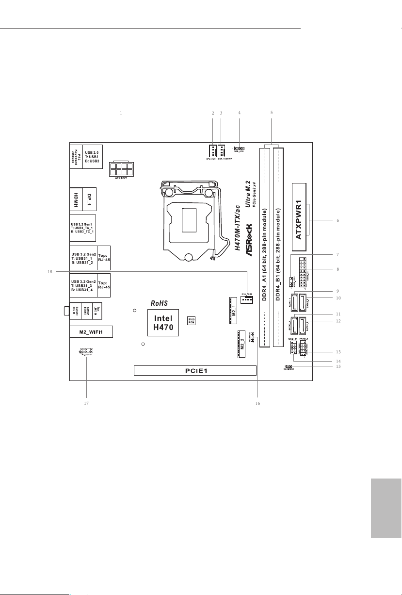
1.3 Motherboard Layout
8
English
No. Description
1 ATX 12V Power Connector (ATX12V1)
2 CPU Fan Connector (CPU_FAN1)
3 Chassis/Waterpump Fan Connector (CHA_FAN1/WP)
4 RGB LED Header (RGB_LED1)
5 2 x 288-pin DDR4 DIMM Slots (DDR4_A1, DDR4_B1)
6 ATX Power Connector (ATXPWR1)
7 Addressable LED Header (ADDR_LED1)
8 USB 3.2 Gen1 Header (USB3_ 34)
9 SATA3 Connector (SATA3_1)
10 SATA3 Connector (SATA3_0)
11 SATA3 Connector (SATA3_3)
12 SATA3 Connector (SATA3_2)
13 System Panel Header (PANEL1)
14 USB 2.0 Header (USB_34)
15 Clear CMOS Jumper (CLRMOS1)
16 Chassis Speaker Header (SPEAKER1)
17 Front Panel Audio Header (HD_AUDIO1)
18 Chassis Fan Connector (CHA_FAN2)
9
English
H470M-ITX/ac
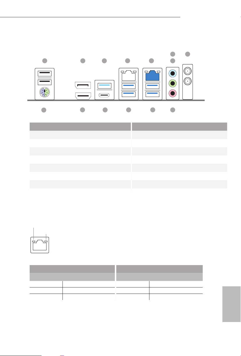
1.4 I/O Panel
No. Description No. Description
1 USB 2.0 Ports (USB12) 8 Antenna Ports
2 DisplayPort 1.4 9 Microphone (Pink)***
3 USB 3.2 Gen1 Type-A Port (USB3_TA_1) 10 USB 3.2 Gen2 Type-A Ports (USB31_34)
4 LAN RJ-45 Port (Intel® I219V)* 11 USB 3.2 Gen2 Type-A Ports (USB31_12)
5 2.5G LAN RJ-45 Port (Dragon RTL8125BG)** 12 USB 3.2 Gen1 Type-C Port (USB3_TC_1)
6 Line In (Light Blue)*** 13 HDMI Port
7 Front Speaker (Lime)*** 14 PS/2 Mouse/Keyboard Port
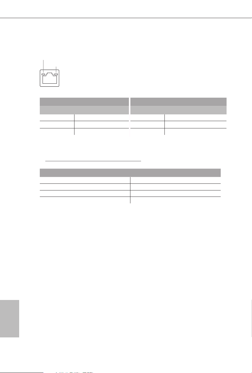
* ere are two LEDs on each LAN port. Please refer to the table below for the LAN port LED indications .
Activity / Link LED Speed LED
Status Description Status Description
O No Link O 10Mbps connection
Blinking Data Activity Orange 100Mbps connection
On Link Green 1Gbps connection
ACT/LINK L ED
SPEED LE D
LAN Por t
1
13 1011
12
4 5
9
7
6
3
8
14
2
10
English
ACT/LINK L ED
SPEED LE D
LAN Por t
** ere are two LEDs on each LAN port. Please refer to the table below for the LAN port LED indications.
Activity / Link LED Speed LED
Status Description Status Description
O No Link O 10Mbps connection
Blinking Data Activity Orange 100Mbps/1Gbps connection
On Link Green 2.5Gbps connection
*** Functi on of the Audio Por ts in 7.1-channel Con guration:
Port Function
Light Blue (Rear panel) Rear Speaker Out
Lime (Rear panel) Front Speaker Out
Pink (Rear panel) Central /Subwoofer Speaker Out
Lime (Front panel) Side Speaker Out

11
English
H470M-ITX/ac
1.5 WiFi-802.11ac Module and ASRock WiFi 2.4/5 GHz
Antennas
WiFi-802.11ac + BT Module
is motherboard comes with an exclusive WiFi 802.11 a/b/g/n/ac + BT v4.2
module (pre-installed on the rear I/O panel) that oers support for WiFi 802.11 a/b/
g/n/ac connectivity standards and Bluetooth v4.2. WiFi + BT module is an easy-to-
use wireless local area network (WLAN) adapter to support WiFi + BT. Bluetooth
v4.2 standard features Smart Ready technology that adds a whole new class of
functionality into the mobile devices. BT 4.2 also includes Low Energy Technolog y
and ensures extraordinary low power consumption for PCs.
* e transmission speed may vary according to the environment.
12
English
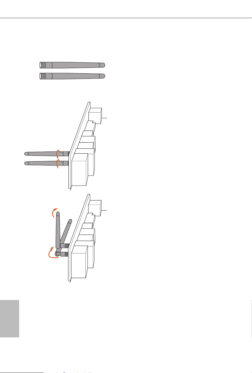
WiFi Antennas Installation Guide
Step 1
Prepare the WiFi 2.4/5 GHz Antennas that come
with the package.
Step 2
Connect the two WiFi 2.4/5 GHz Antennas to
the antenna connectors. Turn the antenna clock-
wise until it is securely connected.
Step 3
Set the WiFi 2.4/5 GHz Antenna as shown in the
illustration.
*You may need to adjust the direction of
the antenna for a stronger signal.

13
English
H470M-ITX/ac
is is a Mini-ITX form factor motherboard. Before you install the motherboard,
study the conguration of your chassis to ensure that the motherboard ts into it.
Pre-installation Precautions
Take note of the following precautions before you install motherboard components
or change any motherboard settings.
•
Make sure to unplug the power cord before installing or removing the motherboard
components. Failure to do so may cause physical injuries and damages to motherboard
components.
•
In order to avoid damage from static electricity to the motherboard’s components,
NEVER place your motherboard directly on a carpet. Also remember to use a grounded
wrist strap or touch a safety grounded object before you handle the components.
•
Hold components by the edges and do not touch the ICs.
•
Whenever you uninstall any components, place them on a grounded anti-static pad or
in the bag that comes with the components.
•
When placing screws to secure the motherboard to the chassis, please do not over-
tighten the screws! Doing so may damage the motherboard.
Chapter 2 Installation
14
English
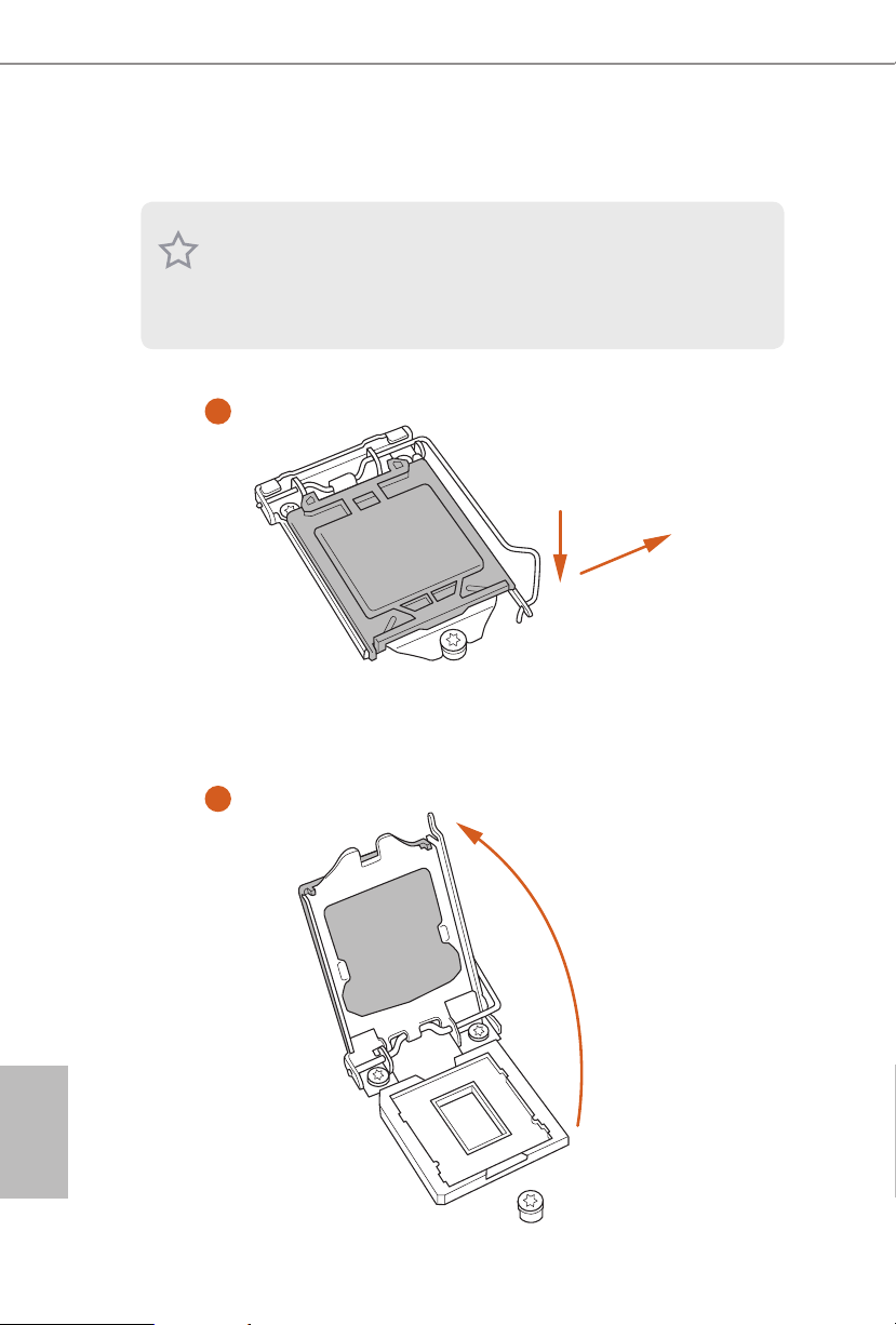
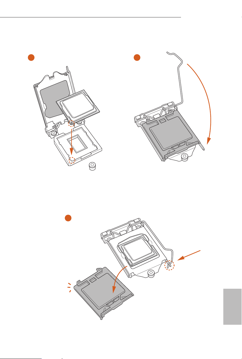
2.1 Installing the CPU
1. Before you insert the 120 0-Pin CPU into the socket, please check if the PnP ca p
is on the socket, if the CPU sur face is unclean, or if th ere are any b ent pins in the
socket. Do not force to insert the CPU into the socket if above situ ation is found.
Other wise, the CPU wil l be seriously d amaged.
2. Unplug all power cables be fore installing the CPU.
1
2
A
B
15
English
H470M-ITX/ac
4
5
3

16
English
Please save and replace the cover if the processor i s removed. e cover must be
placed if you wish to return the motherboard for aer service.
17
English
H470M-ITX/ac
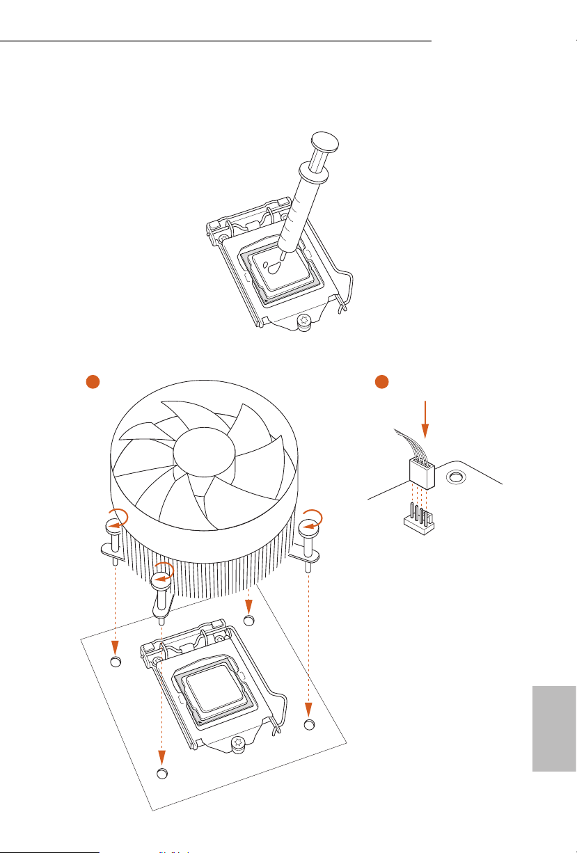
2.2 Installing the CPU Fan and Heatsink
1 2
CPU_FAN
18
English
2.3 Installing Memory Modules (DIMM)
is motherboard provides two 288-pin DDR4 (Double Data Rate 4) DIMM slots,
and supports Dual Channel Memory Technology.
e DIMM only ts in one correct orie ntation. It will cause permanent dam age to
the mothe rboard and the DIMM if you force the DIMM into the slot at incor rect
orientation .
1. For dual channel conguration, you always need to install identica l (the same
brand, speed , size and chip-type) DDR4 DIMM pairs.
2. It is unable to activate Dual Channel Memor y Technology with only one memory
module instal led.
3. It is not allowed to install a DDR, DDR2 or DDR3 memory module into a DDR4
slot; otherwise, this motherboard and DIMM may be damaged.
19
English
H470M-ITX/ac
1
2
3
20
English
2.4 Expansion Slots (PCI Express Slot)
ere is 1 PCI Express slot slot on the motherboard.
PCIe slot:
PCIE1 (PCIe 3.0 x16 slot) is used for PCI Express x16 lane width graphics cards.
Before installing an ex pansion card, please make sure that the power supply is
switched o or the power cord is unplugged. Plea se read the documentation of the
expan sion card and mak e necessary hardware settings for the card before you start
the installation.
21
English
H470M-ITX/ac
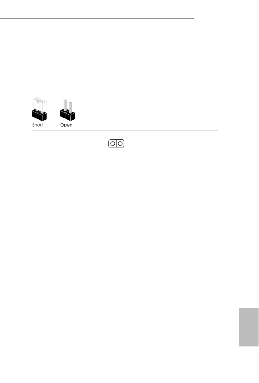
2.5 Jumpers Setup
e illustration shows how jumpers are setup. When the jumper cap is placed on
the pins, the jumper is “Short”. If no jumper cap is placed on the pins, the jumper is
“Open”.
Clear CMOS Jumper
(CLRMOS1)
(see p.7, No. 15)
CLRMOS1 allows you to clear the data in CMOS. To clear and reset the system
parameters to default setup, please turn o the computer and unplug the power
cord from the power supply. Aer waiting for 15 seconds, use a jumper cap to
short the pins on CLR MOS1 for 5 seconds. However, please do not clear the
CMOS right aer you update the BIOS. If you need to clear the CMOS when you
just nish updating the BIOS, you must boot up the system rst, and then shut it
down before you do the clear-CMOS action. Please be noted that the password,
date, time, and user default prole will be cleared only if the CMOS battery is
removed. Please remember toremove the jumper cap aer clearing the CMOS.
2-pin Jumper
Loading...