


mini-tank electric water heaters
chauffe-eau électriques à miniréservoir
calentadores de agua eléctricos de minitanque
Meets ASHRAE
90.1 standard
INSTALLATION MANUAL FOR
DIRECTIVES D’INSTALLATION POUR INSTRUCCIONES DE SEGURIDAD IMPORTANTES
GL2.5Ti
GL4Ti
GL8Ti
CONTROLLED ENERGY CORPORATION
340 Mad River Park Waitsfield, Vermont 05673
800-798-8161 • www.Protankless.com

IMPORTANT SAFETY INSTRUCTIONS
WARNING |
When using electrical appliances, safety precautions to reduce the risk of fire, electric |
|
|
shock or injury to persons should be followed, including: |
|
|
1. |
READ ALL INSTRUCTIONS BEFORE USING THIS WATER HEATER. |
|
2. |
This water heater must be grounded. Connect only to properly grounded outlet. |
|
|
See “GROUNDING INSTRUCTIONS” found on “INSTALLATION INSTRUCTIONS”. |
|
3. |
Install or locate this water heater only in accordance with the provided installation |
|
|
instructions. |
|
4. |
Use this water heater only for its intended use as described in this manual. |
|
5. |
Do not use an extension cord set with this water heater. If no outlet is available |
|
|
adjacent to the water heater, contact a qualified electrician to have one properly |
|
|
installed. |
|
6. |
As with any appliance, close supervision is necessary when used by children. |
|
7. |
Do not operate this water heater if it is not working properly or if it has been |
|
|
damaged or dropped. |
|
8. |
This water heater should be serviced only by qualified service personnel. Contact |
|
|
a service person for examination, repair or adjustment. |
|
9. |
Failure to service the anode rod at least once a year could cause the tank to fail |
|
|
and leak. |
|
|
Any water heater should be installed in such a manner that if it should leak, the |
|
|
resulting flow of water will not cause damage to the area in which it is installed. |
|
|
National Plumbing codes require a drain pan for any water heater installation. |
|
|
Failure to install one is the sole responsibility of owner and/or installer. Reference |
|
|
UPC 2000 (Uniform Plumbing Code) Section 510 - Protection from Damage or |
IPC 200 (International Plumbing Code) Section 504Safety Devices.
KEEP THESE INSTRUCTIONS AT HAND SAVE THESE INSTRUCTIONS
Technical data
MODEL |
|
GL 2.5 Ti |
GL 4 Ti |
GL 8 Ti |
Capacity |
gallons |
2.75 |
3.85 |
7.0 |
Voltage |
Vac |
110/120 for each model |
||
Power at 120 Vac |
Watts |
1500 |
1500 |
1500 |
Maximum Water pressure |
psi |
150 |
150 |
150 |
|
|
|
|
|
Weight |
Lbs |
15.5 |
17.3 |
29.5 |
|
|
|
|
|
Amperage |
Amps |
12.50 for each model |
||
|
|
|
|
|
Phases |
|
1 |
1 |
1 |
|
|
|
|
|
WARNING The installer should review the contents of this manual with the owner upon completion of installation, and the manual should be left with the owner and placed in a location close to the installation.
1

FIG. 1/1 |
|
|
|
|
|
Temperature & pressure |
|
|
Hot water outlet |
|
|
|
relief valve, 3/4 NPT male |
||
|
1/2 NPT male |
|
|
|
|||
|
|
|
|
|
|
||
|
|
|
|
|
|
|
|
|
|
|
|
|
|
|
|
Cold water inlet 1/2 NPT male
 Temperature & pressure relief
valve discharge 3/4 NPT female line to drain tapping for
relief valve
COMPONENT
PARTS OF
GL 2.5Ti - 4Ti
FIG. 1/2 Temperature & pressure relief
3/4 NPT female tapping for relief valve
3/4 NPT female tapping
COMPONENT PARTS OF GL 8Ti (Horizontal installation)
Hot water outlet 3/4 NPT male
3/4 NPT male plug
 Temperature & pressure relief valve discharge line to drain
Cold water inlet 3/4 NPT male
FIG. 1/3 |
|
|
|
|
|
|
|
Temperature & pressure |
|
COMPONENT |
|||||
|
|
relief |
|
||||
|
|
|
PARTS OF |
||||
|
|
|
|
|
|
||
Hot water outlet |
|
|
|
|
GL 8Ti |
||
3/4 NPT male |
|
|
|
|
|
(Vertical |
|
|
|
|
|
|
|
installation) |
|
3/4 NPT female |
|
|
|
|
|
Temperature & |
|
tapping for |
|
|
|
|
|
||
relief valve |
|
|
|
|
|
pressure relief |
|
|
|
|
|
|
|||
|
|
|
|
|
|
|
valve discharge |
|
|
|
|
|
|
|
line to drain |
3/4 NPT male plug |
|
|
|
|
|
|
|
3/4 NPT female |
|
|
|
|
|
|
|
tapping |
|
|
|
|
|
|
|
|
|
|
|
|
|
|
|
2
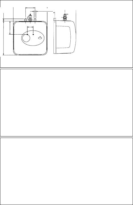
FIG. 2/1
1”
5 1/2”
14”
DIMENSIONS FOR GL 2.5Ti - GL 4Ti
14” |
10 1/4” |
|
12 1/4” |
|
3 3/4” |
|
|||
6” |
GL 2.5 |
7 1/2” |
||
|
||||
|
1/2 NPT MALE |
|
3” |
|
|
3 1/2” |
|
||
2 1/2” |
|
|
|
GL 4
FIG. 2/2 DIMENSIONS FOR GL 8Ti (HORIZONTAL INSTALLATION)
14 1/2”
81/2” 4 1/2”
|
3/4 NPT MALE |
17 1/2” |
11 1/2” |
|
3” |
|
17 1/2” |
FIG. 2/3 |
DIMENSIONS FOR GL 8 Ti (VERTICAL INSTALLATION) |
3/4 NPT MALE
6 1/2”
14 1/2”
11 1/2” |
|
|
8 1/2” |
|
|
|
|
|
|
|
4 1/2” |
|
1” |
||
2 1/2” |
|
|
|
|
|
|
|
|
|
|
|
|
17 1/2” |
||
17 1/2”
3
 Loading...