


Instructions
AME 15 QM
|
AME 15 QM + |
AME 15 QM + |
|
|
AB-QM (DN 40/50) |
AB-QM (DN 65 - 100) |
|
English |
AME 15 QM |
www.danfoss.com |
Page 4 |
DANSK |
AME 15 QM |
www.danfoss.dk |
Side 5 |
DEUTSCH |
AME 15 QM |
www.danfoss.de |
Seite 6 |
FRANÇAIS |
AME 15 QM |
www.danfoss.fr |
Page 7 |
ESPAÑOL |
AME 15 QM |
www.danfoss.es |
Page 8 |
NEDERLANDS |
AME 15 QM |
www.danfoss.nl |
Page 9 |
SUOMI |
AME 15 QM |
www.danfoss.fi |
Sivu 10 |
POLSKI |
AME 15 QM |
www.danfoss.pl |
Strona 11 |
РУССКИЙ |
AME 15 QM |
www.danfoss.ru |
Страница 12 |
|
AME 15 QM |
www.danfoss.com.cn |
13 |
73691190 DH-SMT/SI |
VI.LE.A1.8C © Danfoss 09/2007 |
1 |

1 |
3 |
|
|
|
|
|
|
|
2 |
|
|
4 |
5 |
|
|
|
|
73691190 DH-SMT/SI |
VI.LE.A1.8C © Danfoss 09/2007 |
2 |
5 |
|
|
73691190 DH-SMT/SI |
VI.LE.A1.8C © Danfoss 09/2007 |
3 |
DEUTSCHEnglish
Safety Note
To avoid injury of persons and damages to the device, it is absolutely necessary to read and observe these instructions carefully.
Necessary assembly, start-up, and maintenance work must be performed by qualified and authorized personnel only.
Prior to assembly and depressurizing the system.
Please comply with the instructions of the system manufacturer or system operator.
Mounting 2
Fix the actuator AME 15QM on the valve 3 .
Wiring 4
Control signal
Control signal from the controller must be connected to terminals Y (input signal) and SN (common) on the AME printed board.
Output signal
Output signal from the terminal X can be used for indication of the current position. Range depends on the DIP switch settings.
Supply voltage
Supply voltage
(24 V~ -15 to +10%, 50 Hz) must be connected to the terminals SN and SP.
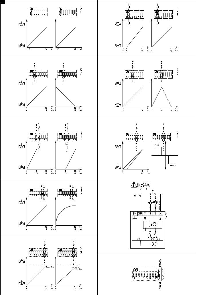
DIP switch settings 5
Factory settings:
ALL switches are on OFF position!
5
Note:
All combinations of DIP switches are allowed. All functions that are selected are added consecutively. There is only one logic override of functionalities i.e. the switch No.6 Proportional / 3 point, which sets actuator to ignore control signal and works as a “simple” 3-point actuator.
SW 1: U/I
Actuator can responde to a voltage or current control signal. With switch No.1: U/ I actuator can be set either to operate with a voltage control signal (actuator responds to signal between 0 … 10 V), or current control signal (actuator responds to signal between 0 … 20 mA).
Factory setting:
voltage control signal (0 … 10 V).
SW 2: 2V … 10 / 0V … 10
Actuator can be set to response on a control signal from 2 V, or 0 V. If the actuator is set to current signal than it responds to control signal from 4 mA or 0 mA.
Factory setting is:
2 … 10V.
SW 3: Direct/Inverse
Actuator can be set for spindle to travel downwards on rising control signal (DIRECT), OR for spindle to travel upwards on rising control signal (INVERSE).
Factory setting is:
DIRECT
SW 4: ---/Sequential
Two actuators can be set to work parallel with one control signal. If the SEQUENTIAL is set than an actuator responds to split control signal (see 0(2) V … 5(6 V) /
6(6) V … 10 V).
Note:
This combination works in combination with switch No.5: 0(2) V … 5(6 V) / 6(6) V … 10 V
SW 5: 0(2) V … 5(6 V)/6(6) V … 10 V
Note:
This function is available if switch No.4:
--- / Sequential is set.
Actuator can be set to match the range of the control signal:
2 … 6 V (switch No.2: 2 V … 10) 0 … 5 V (switch No.2: 0 V … 10)
4 … 12 mA (switch No.2: 2 V … 10) 0 … 10 mA (switch No.2: 0 … 10)
OR
6 … 10 V (switch No.2: 2 V … 10) 5 … 10 V (switch No.2: 0 V … 10)
12 … 20 mA (switch No.2: 2 V … 10) 10 … 20 mA (switch No.2: 0 … 10)
SW 6: Proportional/3 point
Actuator can operate as “simple” 3-point actuator, if the 3-point function is selected. Power supply should be connected on
SN and SP ports. On port 1 or 3 24 VAC signal is connected for rising or lowering of actuator. Return signal X indicates the correct position.
Note:
if 3 point function is selected actuator does not respond to any control signal on port Y. It only rises and lowers spindle if power is supplied on port 1 or 3.
SW 7: LOG. flow/LIN. flow
Almost all Danfoss valves that fit the actuator have logarithmic (equal percentage) flow/position characteristic. With setting switch to LIN. flow the characteristic of motorised valve can be affected. Combination of actuator and valve can work together as valve with LINEAR characteristic.
Factory setting:
LOG. Flow (characteristic of valve is unchanged)
NOTE:
If this function is used in combination with non-logarithmic valves the characteristic of motorised valve will be anti-logarithm of valve’s characteristic (e.g. valve with linear characteristic will be transformed to quick open characteristic).
SW 8: 100% KVS/RED. KVS
To be set on OFF position.
SW 9: Reset
After the actuator has been connected to power supply, the actuator will start the self-adjustment procedure. The indicator LED flashes until self adjustment is finished. The duration depends on the spindle travel and will normally last a few minutes. The stroke length of the valve is stored in the memory after self adjustment has been completed. To restart self adjustment, change the position of RESET switch (switch No.9). If the supply voltage is switched off or falls below 80% in more than 0.1s, the current valve position will be stored in the memory and all data remain saved in the memory also after a power supply cut-out.
Function test
The indicator light shows whether the positioner is in operation or not. Moreover, the indicator shows the control status and faults.
Constant light
-normal operation No light
-no operation or no power supply
Intermittent light (1 Hz)
-self adjusting-mode Intermittent light (3 Hz):
-power supply too low
-insufficient valve stroke (<20 s)
-end-position cannot be reached.
73691190 DH-SMT/SI |
VI.LE.A1.8C © Danfoss 09/2007 |
4 |
DANSK
Sikkerhedsbestemmelser
For at undgå personskader og erstatningsskader på produkter, er det absolut nødvendig at gennemlæse følgende instruktion.
Montering, opstart og vedligeholdelse må kun foretages af kvalificeret og autoriseret personale.
Før montering eller demontering skal anlægget gøres trykløst.
Leverandørens retningslinier skal følges.
Montering 2
Fastgør AME 15QM på ventilen 3 .
Elektrisk tilslutning 4 Styresignal
Styresignalet fra regulatoren skal tilsluttes terminal Y (indgangssignal) og SN (fælles) på AME´s klemrække.
Udgangssignal
Udgangssignal fra terminal X kan anvendes til indikering af aktuel position.
Området afhænger af DIP kontakternes indstilling.
Forsyningsspænding
Forsyningsspændingen (24 V~ -15/+10%, 50 Hz) skal tilsluttes klemme SN og SP
Indstilling af DIP kontakter 5
Fabriksindstilling:
Alle kontakter er I OFF position!
Bemærk:
Alle kombinationer af kontaktindstillinger er tilladelige. Alle funktionsvalg er tilføjet en efter en. Der er kun en logisk overskridelse af funktionaliteten: Kontakt Nr. 6 Proportional / 3-punkt styring, som sætter aktuatoren i stand til at ignorere reguleringssignalet og arbejde som en ”simpel” 3- punkt motor
SW1: U / I
Aktuatoren kan modtage reguleringssignaler i spænding eller strøm. Med kontakt Nr.1: U / I kan aktuatoren indstilles til at arbejde med spændingssignal (aktuatoren reagerer på signal mellem 0…10V), eller strømsignal (aktuatoren reagerer på signal mellem 0…20mA).
Fabriksindstilling
Spændingssignal (0 … 10 V).
SW2: 2V…10/ 0V…10
Aktuatoren kan indstilles til at reagere på signaler fra 2V, eller 0V.
Er aktuatoren indstillet til strømsignal, reagerer aktuatoren på signaler fra 4mA eller 0mA.
Fabriksindstilling:
2 … 10V.
SW3: Direkte / Indirekte
Aktuatoren kan indstilles til nedadgående spindel ved stigende kontrolsignal (DIREKTE)
Eller opadgående spindel ved stigende kontrolsignal (INDIREKTE)
Fabriksindstilling:
DIREKTE
SW4: ---/ Sekvens
To aktuatorer kan arbejde parallelt med et reguleringssignal.
I SEKVENS indstilling reagerer aktuatoren på delt styresignal (se 0(2)V…5(6V) / 6(6)V…10V).
Bemærk:
Denne kombination arbejder sammen med kontakt Nr. 5: 0(2)V…5(6V) / 6(6)V…10V
SW5: 0(2)V…5(6V) / 6(6)V…10V
Bemærk:
Denne funktion er tilgængelig hvis kontakt Nr. 4:---/ Sekvens er indstillet. Aktuatoren kan afpasses til styresignalet:
2 … 6 V (kontakt Nr.2: 2 V … 10) 0 … 5 V (kontakt Nr.2: 0 V … 10)
4 … 12 mA (kontakt Nr.2: 2 V … 10) 0 … 10 mA (kontakt Nr.2: 0 … 10)
Eller
6 … 10 V (kontakt Nr.2: 2 V … 10) 5 … 10 V (kontakt Nr.2: 0 V … 10)
12 … 20 mA (kontakt Nr.2: 2 V … 10) 10 … 20 mA (kontakt Nr.2: 0 … 10)
SW6: Proportional / 3-punkt
Aktuatoren arbejder som en “simpel” 3- punkt aktuator, hvis 3-punkt funktionen er valgt. Forsyningsspænding tilsluttes klemmerne SN og SP. På klemmerne 1 og 3 tilsluttes 24 VAC signal til åbnelukke funktion af aktuatoren. Udgangssignal X indikerer korrekt position.
Bemærk:
Hvis 3-punkt funktionen er valgt, reagerer aktuatoren ikke på signaler på klemme Y. Motorspindelen bevæger sig kun opad eller nedad ved signaler på klemme 1 eller 3.
SW7: LOG. flow / LIN. flow
Næsten alle Danfoss ventiler som passer til aktuatoren har logaritmisk karakteristik. Ved at indstille kontakten på LIN.
flow, påvirkes ventilens karakteristik. Kombination aktuator / ventil arbejder sammen som ventil med LINEÆR karakteristik.
Fabriksindstilling:
LOG.flow (ventilkarakteristikken er uændret).
Bemærk:
Anvendes denne funktion i kombination med ikke logaritmiske ventiler, vil karakteristikken for motorventilen blive modsat logaritmisk
i forhold til ventilkarakteristikken (d.v.s. en ventil med lineær karakteristik vil blive transformeret til hurtig åben karakteristik).
SW 8: 100% KVS/RED. KVS
SW9: Reset
Efter tilslutning af forsyningsspænding, vil aktuatoren starte en selvjusterings procedure. LED indikatoren blinker indtil selvjusteringen er færdig. Varigheden afhænger af spindelvandringen og tager normalt nogle få minutter. Ventilens spindelvandring lagres i hukommelsen efter selvjusteringen er færdig. For at starte selvjustering, skiftes positionen af RESET kontakten (kontakt Nr. 9). Hvis forsyningsspændingen svigter eller falder til under 80% i mere end 0,1 sekund, vil den aktuelle ventilposition lagres i hukommelsen og alle data bliver bevaret i hukommelsen, også efter at forsyningsspændingen afbrydes.
Funktions test
Lysdioden indikerer, om aktuatoren er i drift, ligesom den viser driftsstatus og eventuelle fejl.
Konstant lys
-normal drift Intet lys
-ikke i drift, ingen strømforsyning Interval blink (1Hz)
-selvjusteringsmodul
Interval blink (3 Hz)
-strømforsyning for lav
-ventil slaglængde utilstrækkelig
-endestilling kan ikke nås
73691190 DH-SMT/SI |
VI.LE.A1.8C © Danfoss 09/2007 |
5 |
 Loading...