


SEND |
SIG/ |
SEND |
SIG/ |
SEND |
SIG/ |
|
SEND |
SIG/ |
|
SEND |
SIG/ |
|
SEND |
IG/ |
|
SEND |
SIG/ |
|
SEND |
SIG/ |
|
MASTER LEVEL |
|
||
|
CLIP |
|
|
CLIP |
|
CLIP |
|
|
CLIP |
|
|
CLIP |
|
|
CSLIP |
|
|
CLIP |
|
|
CLIP |
L |
|
||
|
|
CH 1 |
|
|
CH 2 |
|
CH 3 |
|
|
CH 4 |
|
|
CH 5 |
|
|
CH 6 |
|
|
CH 7 |
|
CH 8 |
|
|
|
|
|
|
|
|
|
|
|
|
|
|
|
|
|
|
-10dB |
-5dB 0dB |
+3dB |
+6dB |
||||||||
MIN |
MAX |
MIN |
MAX |
|
MIN |
MAX |
|
MIN |
MAX |
|
MIN |
MAX |
|
MIN |
MAX |
|
MIN |
MAX |
|
MIN |
MAX |
R |
|
|
POWER |
|
|
|
|
|
|
|
|
|
|
|
|
|
|
|
|
|
|
|
|
|
|
EFFECTS RETURN |
MASTER |
||
PAN |
|
PAN |
|
PAN |
|
PAN |
|
PAN |
|
PAN |
|
PAN |
|
PAN |
|
|
|
|
|||||||
MIC/LINE |
MIN |
|
|
MIN |
MAX |
MIN |
MAX |
|
MIN |
MAX |
|
MIN |
MAX |
|
MIN |
MAX |
|
MIN |
MAX |
|
MIN |
MAX |
|
|
|
|
|
L |
R |
|
L |
R |
|
L |
R |
|
L |
R |
|
L |
R |
|
L |
R |
|
L |
R |
MIN |
MAX |
MIN |
MAX |
QUICKSTART GUIDE
ENGLISH ( 3 – 7 )
MANUAL DE INICIO RÁPIDO
ESPAÑOL ( 8 – 12 )
GUIDE D’UTILISATION RAPIDE
FRANÇAIS ( 13 – 17 )
KURZANLEITUNG
DEUTSCH ( 18 – 22 )
MANUALE RAPIDO DI UTILIZZAZIONE
ITALIANO ( 23 – 27 )
BOX CONTENTS
MultiMix8Line
Power Cable
Quickstart Manual
Safety & Warranty Information
PRODUCT REGISTRATION
Please go to http://www.alesis.com to register your new MultiMix8Line. Registration helps you by ensuring that we can keep you up to date on any last-minute product issues. If you want, Alesis can also send you information on other products that might interest you.
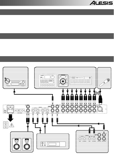
CONNECTION DIAGRAM
LINE-LEVEL AUDIO DEVICES |
MICROPHONE |
CD RECORDER
OR
SPEAKERS
EFFECTS MODULE
TO ANOTHER
MULTIMIX8LINE MIXER
3
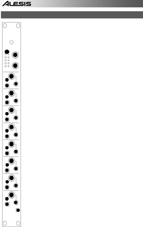
FRONT PANEL OVERVIEW
|
|
|
POWER |
|
|
|
LEVEL |
|
+3dB +6dB 8 |
|
MASTER |
7 |
MIN MAX |
MASTER |
|
L -10dB -5dB 0dB |
R |
EFFECTS RETURN |
6 |
MIN MAX |
|
|
CH8 |
|
|
MAX |
|
|
|
|
1 |
MIN |
|
|
SIG/ |
CLIP |
4 |
|
|
|
|
|
|
|
MIN MAX |
|
|
R |
SEND |
|
3 |
PAN |
2 |
L |
|
|
|
CH7 |
|
|
MAX |
|
|
|
|
1 |
MIN |
|
|
SIG/ |
CLIP |
4 |
|
|
|
|
|
|
|
MIN MAX |
|
|
R |
SEND |
|
3 |
PAN |
2 |
L |
|
|
|
CH6 |
|
|
MAX |
|
|
|
|
1 |
MIN |
|
|
SIG/ |
CLIP |
4 |
|
|
|
|
|
|
|
MIN MAX |
|
|
R |
SEND |
|
3 |
PAN |
2 |
L |
|
|
|
CH5 |
|
|
MAX |
|
|
|
|
1 |
MIN |
|
|
SIG/ |
CLIP |
4 |
|
|
|
|
|
|
|
MIN MAX |
|
|
R |
SEND |
|
3 |
PAN |
2 |
L |
|
|
|
CH 4 |
|
|
MAX |
|
|
|
|
1 |
MIN |
|
|
SIG/ |
CLIP |
4 |
|
|
|
|
|
|
|
MIN MAX |
|
|
R |
SEND |
|
3 |
PAN |
2 |
L |
|
|
|
CH 3 |
|
|
MAX |
|
|
|
|
1 |
MIN |
|
|
SIG/ |
CLIP |
4 |
|
|
|
|
|
|
|
MIN MAX |
|
|
R |
SEND |
|
3 |
PAN |
2 |
L |
|
|
|
CH 2 |
|
|
MAX |
|
|
|
|
1 |
MIN |
|
|
SIG/ |
CLIP |
4 |
|
|
|
|
|
|
|
MIN MAX |
|
|
R |
SEND |
|
3 |
PAN |
2 |
L |
|
|
|
CH 1 |
|
1 |
MIN |
|
SIG/ |
CLIP |
4 |
|
|
|
|
SEND |
|
3 |
MIN MAX |
PAN |
2 |
|
|
|
|
|
|
MIC/LINE |
5 |
1.VOLUME
Adjust the gain for each channel
2.PAN
Adjust the signal's position in the left-right panorama. For stereo connections, this knob acts as a BALANCE control, attenuating the left side of the signal as the knob is moved rightwards, and vice versa.
3.SEND
Adjust the amount of signal sent to an external effects processor. SEND is "post-fader," which means that the amount of signal you send to the external processor will be affected by the VOLUME setting for the channel.
4.SIGNAL/CLIP LED
When normal signal levels are detected, this LED glows green. To minimize distortion, turn down your input source if the LED flashes RED (clip).
5.MIC/LINE
For the first channel, switch between a MICROPHONE input or the LINE inputs on the rear of the unit.
6.EFFECTS RETURN
Adjust the amount of signal sent back to the mixer from an external effects processor.
7.MASTER
Adjust the output volume sent to the MAIN OUTPUTS.
8.MASTER LEVEL METERS
Watch the master level meters for optimal signal level. The MultiMix8Line's meters indicate 0dB at 0dBu.
4

REAR PANEL OVERVIEW
2 |
|
|
|
|
LEFT (MONO) MIC |
|
|
RIGHT |
|
|
|
|
|
CH 1 |
|
|
|
|
CH 2 |
|
|
|
|
CH 3 |
|
|
|
|
CH 4 |
|
1 |
|
|
|
|
|
|
|
CH 5 |
|
|
|
|
CH 6 |
|
|
|
|
CH 7 |
|
|
|
|
CH 8 |
OUT |
3 |
|
IN |
MAIN EXPAND |
4 |
|
5 |
|
BUS LINK |
|
|
|
|
FX |
STEREO MONITOR |
|
|
|
(MONO) |
|
SEND |
|
|
LEFT |
EFFECTS |
|
|
|
RIGHT |
|
6 |
|
(MONO) |
|
|
RETURN |
|
|
LEFT |
|
|
|
|
RIGHT |
LEFT |
7 |
|
RIGHT |
MAIN OUT |
|
|
8 |
|
VOLTAGE |
|
|
|
|
INPUT |
10 |
9 |
|
||
|
|
FUSE F0.5AL,250V |
AC INPUT |
115/230V |
1.8 STEREO OR 16 MONO LINE INPUTS
Plug stereo sources into both the top (LEFT) and bottom (RIGHT) jacks. For mono sources, use only the top (LEFT) jack. Doing this will "normal" the signal to both LEFT and RIGHT inputs. These are unbalanced connections.
Use TS (Tip-sleeve) 1/4" cables for connections. The MultiMix8Line provides a wide gain range suitable for simultaneous use of both -10dbV (consumerlevel) and +4dBu (professional-level) equipment.
2.OPTIONAL MICROPHONE INPUT ON CHANNEL 1
Select MIC or LINE for channel 1 using the switch on the front panel. Note that a microphone must be connected to the XLR (3-pin) input and is always treated as a mono signal.
You must select either MIC or LINE. It is not possible for channel 1 to process microphone AND quarter-inch signals at one time.
Note that the MultiMix8Line does not feature phantom power. Ensure that your microphone does not require phantom power for operation.
Once you have connected your sources, adjust their volume, pan position, and aux send levels. (See below for more on Aux Send and Return.)
3.MAIN EXPAND IN and OUT jacks
You can chain together as many MultiMix8Line mixers as you like by connecting the MAIN EXPAND OUT jack of mixer A into the MAIN EXPAND IN jack of mixer B. Continue connecting additional mixers in similar fashion (OUT B into IN C, OUT C into IN D, etc.). Use a stereo (TRS) cable for these connections. The final mixer in the chain will control the MASTER volume for all of the devices connected to all the mixers. Connect the final mixer in the chain to your output device (amplifier, powered speakers, main mixer, etc.) via the MAIN OUTPUT jacks.
The MAIN EXPAND OUT signal is tapped before the EFFECTS RETURN and MASTER controls. Therefore, for any particular mixer, any signal sent from this jack will not be affected by the position of these controls.
4.STEREO MONITOR OUTPUT
This is an additional, unbalanced output that you can connect to a headphone amplifier, auxiliary recorder, or other device. This signal is tapped AFTER the MASTER volume knob: its level follows the MASTER volume setting.
To connect the STEREO MONITOR OUTPUT to stereo equipment with separate Left and Right inputs, use a TRS-to-dual-TS 1/4" cable. A standard "Insert" cable, available from your audio dealer, is ideal for this application. Connect the TRS (stereo) plug to the MultiMix8Line. Then, connect the two separate TS (mono) plugs to the target device, "Tip" signal Left and "Ring" signal Right.
5

5.EFFECTS BUS LINK
If you own two MultiMix8Line mixers, you can connect them so that they can share one external processor. Use a TRS-to-dual-TS 1/4" cable such as a standard "Insert" cable. Connect the two separate TS (mono) plugs to the EFFECTS SEND of the first mixer, "Tip" signal Left and "Ring" signal Right. Connect the TRS (stereo) end of the cable to the second mixer.
Connect your external effects processor to the EFFECTS SEND and EFFECTS RETURN jacks of the second mixer. The AUX SEND levels from both mixers will now be routed to the effects processor. Control the overall effect level using the EFFECTS RETURN knob on the front of the second mixer.
6.STEREO EFFECTS SEND and RETURN
Connect a reverberation unit (such as the Alesis MidiVerb4) or other effects processor to these jacks in order to add effects to your mix. Connect the input INTO your effects processor to the EFFECTS SEND jacks. Connect the output FROM your effects processor to the EFFECTS RETURN jacks. If you are using a mono effects processor, connect only the LEFT (MONO) jacks of the MultiMix8Line. Using the LEFT (MONO) jack only, the effects return will be heard through both LEFT and RIGHT output channels.
Once your effects processor is connected, use the AUX SEND knob on each channel to adjust the amount of effect applied to that channel.
Consider setting your effects processor to "100% wet" so that it sends only effected signal back to the MultiMix8Line. This will make it easier to dial in just the right effect amount using the channels' AUX SEND knobs and the master EFFECTS RETURN knob.
These are unbalanced connections. Use TS (Tip-sleeve) 1/4" cables for connections.
7.MAIN OUTPUTS
Connect the MultiMix8Line to its destination output device (amplifier, powered speakers, main mixer, etc.) using the main outputs. These are balanced jacks, so use TRS cables for best results. The MAIN OUTPUT level is controlled by the MASTER volume knob on the front panel.
8.VOLTAGE SELECTION SWITCH
VERY IMPORTANT! Slide the voltage selector to the appropriate setting for your power source.
9.FUSE
The fuse is user replaceable. To ensure proper operation, replace only with a fuse of the rated type as shown on the rear of the unit.
10.AC POWER CABLE
The MultiMix8Line contains a built-in power supply with switchable international voltage. Use an IEC power cable to connect to a power source.
6

SPECIFICATIONS
TEST CONDITIONS
-Master level = max
-Effects Return level = min
-Signal fed into left/mono input of channel under test
-For channel under test, gain = mid, pan = mid, effects = min
-For all other channels, gain = min, pan = mid, effects = min
LINE INPUTS
THD+N: 0.005% @ 1kHz, 16dBu SNR A-weighted: 101dB
Frequency response: +0.1dB / -1dB @ 20kHz
Intra-channel crosstalk (left-to-right within one channel): -55.5dB typical @ 10kHz, 15dBu Inter-channel crosstalk (between adjacent channels): -47.0dB typical @ 10kHz, 15dBu
MICROPHONE INPUT
THD+N: 0.007% @ 1kHz, -24dBu, 600Ohms
SNR A-weighted: 90dB
Frequency response: -2.5dB @ 20Hz, -4.25dB @ 20kHz
EFFECTS SENDS
Max output: 17dBu (unbalanced)
THD+N: 0.002% @ @ 1kHz, 16dBu
STEREO OUTPUT
Max output: 26dBu (balanced)
SNR with all channel levels at min = 101.5dB
SNR with all channel levels at max = 103.0dB
7

CONTENIDO DE LA CAJA
MultiMix8Line
Cable de alimentación
Manual de inicio rápido
Información sobre la seguridad y la garantía
REGISTRACIÓN DEL PRODUCTO
Por favor visite http://www.alesis.com para registrar su nuevo MultiMix8Line. Registrarse le permite asegurarse de que lo podamos mantener al tanto de cualquier asunto de último momento relacionado con el producto. Si desea, Alesis también le puede enviar información de otros productos que le puedan interesar.
DIAGRAMA DE CONEXIONES
DISPOSITIVOS DE AUDIO DE NIVEL DE LÍNEA |
MICRÓFONO |
GRABADOR DE CD
O
ALTAVOCES
MÓDULOS DE EFECTOS
A OTRO MEZCLADOR
MULTIMIX8LINE
8

VISTA DEL PANEL FRONTAL
|
|
|
POWER |
|
|
|
LEVEL |
|
+3dB +6dB 8 |
|
MASTER |
7 |
MIN MAX |
MASTER |
|
L -10dB -5dB 0dB |
R |
EFFECTS RETURN |
6 |
MIN MAX |
|
|
CH8 |
|
|
MAX |
|
|
|
|
1 |
MIN |
|
|
SIG/ |
CLIP |
4 |
|
|
|
|
|
|
|
MIN MAX |
|
|
R |
SEND |
|
3 |
PAN |
2 |
L |
|
|
|
CH7 |
|
|
MAX |
|
|
|
|
1 |
MIN |
|
|
SIG/ |
CLIP |
4 |
|
|
|
|
|
|
|
MIN MAX |
|
|
R |
SEND |
|
3 |
PAN |
2 |
L |
|
|
|
CH6 |
|
|
MAX |
|
|
|
|
1 |
MIN |
|
|
SIG/ |
CLIP |
4 |
|
|
|
|
|
|
|
MIN MAX |
|
|
R |
SEND |
|
3 |
PAN |
2 |
L |
|
|
|
CH5 |
|
|
MAX |
|
|
|
|
1 |
MIN |
|
|
SIG/ |
CLIP |
4 |
|
|
|
|
|
|
|
MIN MAX |
|
|
R |
SEND |
|
3 |
PAN |
2 |
L |
|
|
|
CH 4 |
|
|
MAX |
|
|
|
|
1 |
MIN |
|
|
SIG/ |
CLIP |
4 |
|
|
|
|
|
|
|
MIN MAX |
|
|
R |
SEND |
|
3 |
PAN |
2 |
L |
|
|
|
CH 3 |
|
|
MAX |
|
|
|
|
1 |
MIN |
|
|
SIG/ |
CLIP |
4 |
|
|
|
|
|
|
|
MIN MAX |
|
|
R |
SEND |
|
3 |
PAN |
2 |
L |
|
|
|
CH 2 |
|
|
MAX |
|
|
|
|
1 |
MIN |
|
|
SIG/ |
CLIP |
4 |
|
|
|
|
|
|
|
MIN MAX |
|
|
R |
SEND |
|
3 |
PAN |
2 |
L |
|
|
|
CH 1 |
|
1 |
MIN |
|
SIG/ |
CLIP |
4 |
|
|
|
|
SEND |
|
3 |
MIN MAX |
PAN |
2 |
|
|
|
|
|
|
MIC/LINE |
5 |
1.VOLUMEN
Para ajustar la ganancia de cada canal
2.PAN (Desplazamiento izq-der)
Para ajustar la posición de la señal en el panorama izquierda-derecha. En las conexiones estéreo, esta perilla actúa como control de BALANCE, atenuando el lado izquierdo de la señal cuando la perilla se mueve a la derecha y viceversa.
3.SEÑAL ENVIADA
Para ajustar la magnitud de señal enviada a un procesador de efectos externo. El control SEND está ubicado "post-fader", lo que significa que la magnitud de señal que se envía al procesador será afectada por el ajuste de VOLUMEN correspondiente al canal.
4.LED DE SEÑAL/RECORTE:
Cuando se detectan niveles de señal normales, este LED se enciende con luz verde. Para minimizar la distorsión, se debe bajar el nivel de su fuente de entrada si el LED destella con luz ROJA (recorte).
5.MICRÓFONO/LÍNEA
Conmuta para el primer canal entre una entrada de MICRÓFONO o las entradas de LÍNEA de la parte trasera de la unidad.
6.RETORNO DE EFECTOS
Para ajustar la magnitud de señal enviada de retorno al mezclador desde un procesador de efectos externo.
7.MASTER (Nivel maestro)
Para ajustar el volumen de salida enviado a las SALIDAS PRINCIPALES.
8.MEDIDORES DE NIVEL MAESTRO
Observando estos medidores puede obtenerse el nivel óptimo de señal Los medidores del MultiMix8Line 0dB a 0dBu.
9
 Loading...