


Contents
Welcome! .......................................................... |
3 |
About the ADAT HD24...................................... |
3 |
Important features of your ADAT HD24 .... |
3 |
ADAT HD24 key features:.................................. |
5 |
How to Use This Manual........................... |
6 |
Important Safety Instructions................................... |
7 |
Instructions de Sécurité Importantes (French)...... |
8 |
Beim Benutzen dieses Produktes beachten Sie |
|
bitte die folgenden Sicherheitshinweise: |
|
(German) .......................................................... |
9 |
CE Declaration of Conformity........................... |
10 |
Instructions to the User (FCC Notice)................ |
10 |
Quick Start Guide.................................................. |
11 |
If you can't wait to get started:.......................... |
11 |
Front panel tour—left side................................ |
14 |
Front panel tour—right side ............................. |
15 |
Locate/auto buttons ............................... |
15 |
Special features....................................... |
15 |
About the Display............................................ |
16 |
Rear panel tour................................................ |
17 |
Connections......................................................... |
19 |
Unpacking and Inspection................................ |
19 |
Mounting on a Shelf or Non-Rack |
|
Enclosure ............................................... |
19 |
Installing in a Rack .......................................... |
19 |
Thermal Considerations in Rack |
|
Mounting............................................... |
19 |
Power ............................................................. |
20 |
AC Power Hookup ................................. |
20 |
AC Grounding ....................................... |
20 |
Analog inputs and outputs............................... |
21 |
From the console to the HD24's inputs:..... |
22 |
About Audio Cables ............................... |
23 |
Typical input jack hookups...................... |
23 |
Sync In/Out .................................................... |
24 |
ADAT Optical Digital Inputs and Outputs ........ |
25 |
About 16-bit and 20-bit signal transfers .... |
25 |
High sample rate operation ..................... |
25 |
Footswitches ................................................... |
29 |
The LRC Remote.............................................. |
29 |
Basic Recording and Playback ................................ |
31 |
About the hard drives ...................................... |
31 |
Songs.............................................................. |
31 |
Making A Recording ........................................ |
34 |
Time Counter.......................................... |
34 |
Transport Buttons.................................... |
35 |
Recording ........................................................ |
35 |
Sample Rate Selection.............................. |
35 |
Track Selection and Setting Levels ............ |
36 |
The meters ....................................................... |
37 |
Peak hold modes ..................................... |
37 |
Setting the Recording Level...................... |
38 |
Input Select...................................................... |
39 |
Digital Input ........................................... |
39 |
Clock Source settings when recording |
|
the Digital Input...................................... |
39 |
Using All Input ....................................... |
39 |
Input Monitor Controls..................................... |
40 |
Auto Input.............................................. |
40 |
All Input................................................. |
40 |
Playback .......................................................... |
41 |
Scanning................................................. |
41 |
Scrubbing ............................................... |
41 |
Pitch Control.................................................... |
42 |
Using Locate Points ............................................... |
43 |
Locating .......................................................... |
43 |
Special Locate Points ........................................ |
43 |
Other Locate Commands .................................. |
45 |
Creating A Playback/Record Loop.................... |
45 |
Automated Recording ...................................... |
47 |
Rehearsing.............................................. |
48 |
Working with Drives .............................................. |
49 |
Mounting and selecting a drive ......................... |
49 |
How Drives Get Mounted........................ |
50 |
Dismounting drives................................. |
50 |
Adding additional drives.................................. |
51 |
Disk size and recording time .................... |
51 |
Backing up your work ...................................... |
54 |
Editing ................................................................ |
55 |
Editing Controls............................................... |
55 |
Using the Edit Start and Edit End Points ............ |
56 |
Adjusting the Edit Start and Edit End Points ...... |
57 |
Using the Cut and Copy Commands.................. |
58 |
Using the Paste Command................................ |
60 |
Undo............................................................... |
62 |
The Edit Buffer and Levels of Undo .......... |
62 |
Track Slip ........................................................ |
63 |
More about editing........................................... |
64 |
High resolution operation ...................................... |
65 |
88.2/96 kHz sampling rates.............................. |
65 |
The tradeoffs .......................................... |
65 |
Ensuring sample-rate compatibility.......... |
65 |
How ADAT Optical handles a 96 or |
|
88.2k signal ............................................ |
66 |
Using the HD24 with an external High Sample |
|
Rate-capable A/D or D/A converter................. |
66 |
The optional 96k Analog I/O boards................. |
66 |
Synchronization and MIDI ..................................... |
67 |
Synchronization............................................... |
67 |
MIDI Time Code..................................... |
67 |
SMPTE Time Code.................................. |
67 |
MIDI............................................................... |
68 |
Using the HD24 with tape-based ADATs .......... |
69 |
Synchronizing with ADAT ...................... |
69 |
Using the ADAT HD24 with the BRC Master |
|
Remote Control ............................................... |
70 |
Matching start times for synchronization.. 70 |
|
Compatibility issues ............................... |
70 |
Using the HD24 with the M20........................... |
72 |
Using Ethernet ..................................................... |
73 |
When you'd use Ethernet and the HD24............ |
73 |
What you can do..................................... |
73 |
Limitations............................................. |
73 |
Materials you will need.................................... |
74 |
Cables.................................................... |
74 |
Hub ....................................................... |
74 |
Interface card ......................................... |
74 |
Software................................................. |
74 |
Setting the IP parameters of the ADAT HD24 .... |
75 |
About setting up your computer....................... |
76 |
A word of caution................................... |
76 |
Apple Macintosh configuration instructions....... |
77 |
Connection ............................................. |
77 |
Setting up the AppleTalk, TCP/IP and |
|
Remote Access control panels................... |
77 |
Windows 95/98/ME PC configuration |
|
instructions...................................................... |
80 |
Verifying a PC's connection to the |
|
HD24...................................................... |
83 |
Transferring files with Explorer......................... |
84 |
Tips and tricks about Explorer.................. |
85 |
About using FTP download software........ |
85 |
To upload files from the computer to the |
|
HD24............................................................... |
86 |
More about IP addresses................................... |
86 |
About the subnet mask ..................................... |
87 |
About the gateway address............................... |
87 |
Connecting the HD24 directly to a cable or |
|
DSL modem..................................................... |
87 |
To quit FTP server mode................................... |
88 |
An Example Network ....................................... |
89 |
Troubleshooting.................................................... |
91 |
Troubleshooting Index...................................... |
91 |
Avoiding ground loop noise .................... |
93 |
Line Conditioners and Protectors ............. |
93 |
Care and Maintenance ...................................... |
94 |
Cleaning ................................................. |
94 |
Refer All Servicing to Alesis ..................... |
94 |
Obtaining Repair Service ......................... |
95 |
Specifications....................................................... |
97 |
Dimensional drawing ....................................... |
98 |
Index .................................................................. |
99 |
Alesis Limited Warranty ....................................... |
101 |
2 |
ADAT HD24 Reference Manual |

Introduction/Safety Instructions
Welcome!
Thank you for making the Alesis ADAT HD24™ a part of your studio. Since 1984, we've been designing and building creative tools for the audio community. We believe in our products, because we've heard the results that creative people like you have achieved with them. One of Alesis' goals is to make high-quality studio equipment available to everyone, and this Reference Manual is an important part of that. After all, there's no point in making equipment with all kinds of capabilities if no one explains how to use them. So, we try to write our manuals as carefully as we build our products.
The goal of this manual is to get you the information you need as quickly as possible, with a minimum of hassle. We hope we've achieved that. If not, please drop us an email and give us your suggestions on how we could improve future editions of this manual.
We hope your investment will bring you many years of creative enjoyment and help you achieve your goals.
Sincerely,
The people of Alesis Studio Electronics
About the ADAT HD24
Alesis, the company that revolutionized multitrack recording with the introduction of the ADAT, now offers the ADAT HD24 hard disk recorder. The HD24 writes to hard disk in a special way to provide 24 tracks of 24-bit audio on low-cost IDE hard drives, and offers drop-in compatibility with over 150,000 ADAT systems world wide. The ADAT HD24 shatters the cost-per-track price barrier for professional quality audio recording.
Important features of your ADAT HD24
¾Uses affordable, hot-swappable hard drives as removable media:
To allow the use of affordable IDE hard drives as removable recording media, on a cost and performance par with tape, Alesis had to overcome limitations such as data fragmentation that occurs in traditional hard disk recording formats. In order to achieve this, Alesis engineered a new method of writing on hard drives called ADAT FST™, specifically designed for music recording. Unlike the writing schemes employed by computer-based systems, this new method keeps tracks of a given song in adjacent sectors of the hard disk, reducing the required "seek time" for the drive, providing a much greater level of stability in recording and playing back data. Using ADAT FST, seek-to- play functions are virtually instantaneous, and the data fragmentation that can cause hard disk crashes is greatly diminished. As a result, very low-cost, widely available, low-RPM IDE hard drives can be used with exceptional results. For the first time, at about $4 per gigabyte, the cost of the hard disk storage medium is less than that of ADAT tape. Entire 24-track projects can be stored on a single removable drive. Alesis engineered custom drive caddies and protective storage cases to establish today's affordable IDE drives as the new exchange medium for music recording. The HD24 ships with two drive caddies, one loaded with a 10-gigabyte hard drive which will yield approximately 45 minutes of 24-track recording time at 24-bit/48 kHz, and the other ready for you to install your own drive in.
ADAT HD24 Reference Manual |
3 |

Introduction/Safety Instructions
¾Everything you need is built-in:
The HD24 comes complete with 24 channels of analog and digital inputs and outputs—there are no cards or extras to buy to get audio in or out of the recorder. Superb sonic performance was a base-line objective for Alesis. The HD24 provides 24 tracks of high-resolution 24-bit uncompressed linear recording at standard sample rates of 44.1kHz or 48 kHz. It supports 12 tracks at sample rates of 88.2kHz and 96kHz when slaved to external digital products such as A/D, D/A converters, and a forthcoming 96 kHz option will allow high-sample rate analog I/O right from the back panel. An external BNC word clock input is provided for slaving to external clock sources. The HD24 also provides powerful editing capabilities with CUT, COPY, PASTE and multiple UNDO functions across any or all tracks simultaneously.
¾Connects easily to over 150,000 ADAT systems worldwide:
The rear panel of HD24 includes 24 channels of ADAT Optical inputs and outputs and ADAT Sync IN and OUT connectors to allow HD24 to sampleaccurately synchronize with other ADATs, a BRC remote controller, and products from over 100 manufacturers. When connected to a BRC, the HD24 emulates three traditional ADATs. Up to five ADAT HD24 units can be synchronized to make up to 120-track systems, simply by chaining 9-pin cables from the Sync Out of one HD24 to the Sync In of another.
¾Provides multiple methods of file transfer:
The HD24 allows you to move data to and from the recorder in THREE convenient ways:
•The hard drives used by the HD24 are so affordable that drive caddies can be stored on the shelf just like tape, and instantly hotplugged into the front panel when you want to change projects. The ADAT FST drive format establishes removable hard drives as the most reliable, easiest-to-use multitrack media for pro applications. Two front-panel drive bays allow quick retrieval and fast back up of projects. Drives are hotswappable, and fast back-up (a few minutes for an entire drive) is possible between two front-panel drive bays.
•Industry-standard ADAT Optical I/O allows transfer of up to 24 tracks of 24-bit audio simultaneously in real-time using inexpensive fiber-optic cables. The HD24 can easily send digital audio to and from devices such as tape-based ADATs, digital mixing consoles, and computer cards or interfaces.
•A rear-panel Ethernet port allows the HD24 to be connected as a stand-alone FTP server with its own IP address that can be accessed from a computer network, even over the Internet! Songs appear as folders on any Web browser, containing individual .WAV or AIFF files for each track. You can download and upload files from any HD24 connected to a network. Files can then be processed using computer-based editing applications and moved back to the HD24.
4 |
ADAT HD24 Reference Manual |

Introduction/Safety Instructions
ADAT HD24 key features:
1.24 Track simultaneous recording at 44.1/48 kHz
(12 tracks @ 88.2/96 kHz)
2 . Storage media: Standard IDE hard drive (minimum 5,400 RPM)
3.Recording time per each 10 gigabytes @ 48kHz: 45 minutes x 24 tracks; @ 96kHz: 45 minutes x 12 tracks
4 . Number of drive bays: Two front-panel, hotswappable
5.Recording Modes: 44.1/48 kHz
24 track, 16 track, 8 track, 4 track, 2 track 88.2/96 kHz
12 track, 8 track, 6 track, 2 track
6.Resolution: 24 bit linear PCM encoding
7 . Internal clock Fs: 44.1kHz, 48kHz, 88.2kHz, 96kHz; External clock; Varispeed -16%/+6% @48kHz
8.A/D converters: Twenty-four channels of 24 bit, 128x oversampling (standard)
9.D/A converters: Twenty-four channels of 24-bit 128x oversampling (standard)
1 0 . OPTION: 96 kHz-capable A/D/D/A board (Dealer-installed circuit board, replaces standard A/D/D/A circuit board)
11.Analog I/O spec: +4 dBu nominal level (for –15 dBFS digital level) on balanced 1/4" TRS connectors x 48 (standard)
12.Digital I/O: 24 channels (3 each, 8 channels) - ADAT Optical format IN, 24 channels ADAT
Optical OUT, on standard fiber-optic 1mm Toslink-style connectors
13.Synchronization: ADAT Sync. Up to five HD24 units can be synchronized for up to 120 sample-accurate tracks. Control and slaving is possible from any ADAT Sync device.
1 4 . Remote control: Ships with ADAT LRC remote control. HD24 can be also be controlled via ADAT Sync port, or MIDI Machine Control. Optional full-function remote control (available soon).
1 5 . Editing: Cut, Copy, Paste, Move, Insert across any or all tracks. Multiple levels of undo
16.MIDI: IN, OUT. MIDI Time Code transmit; MMC and SYSEX transmit and receive
1 7 . Software update method: Via MIDI or Ethernet
18.Data transfer via Ethernet FTP, 10Base-T, using standard Cat 5 cable (RJ-45 connector)
SONIC PERFORMANCE:
Frequency response: 22Hz - 22kHz ±0.5 dB Total Harmonic Distortion: <.003%
Signal To Noise: > 103dB, A-weighted
Dynamic Range: 144dB, digital IN to digital OUT; > 103 dB analog IN to analog OUT A- weighted
COMPARING MEDIA COST @48kHz:
|
MEDIA |
Recording |
Qty. req'd |
|
Recording Cost |
|
|
UNIT |
time per |
for 24 track, |
|
|
|
|
PRICE |
media unit |
45 min. |
Per track |
Per 24-track |
Per |
|
|
|
project |
minute |
minute |
project |
|
|
|
|
|
|
|
ADAT Tape |
$15.00 ea. |
42 min. x 8 |
3 tapes |
4 cents |
$1.00 |
$45.00 |
(unformatted) |
|
tracks x 20 bit) |
|
|
|
|
|
|
|
|
|
|
|
Standard IDE |
$99.00/ 30 |
135 min. x 24 |
1/3 of a drive |
3 cents |
73 cents |
$33.00 |
Hard Drive |
GB |
track, 24 bit |
(10 GB) |
|
|
|
5400 rpm |
Average |
|
|
|
|
|
ADAT HD24 Reference Manual |
5 |

Introduction/Safety Instructions
How to Use This Manual
This manual is divided into the following sections describing the various functions and applications for the ADAT HD24. While it's a good idea to read through the entire manual once carefully, those having general knowledge about studio equipment should use the table of contents to look up specific functions.
Chapter 1: Quick Start. If you're already experienced with recording, this will get you started using the ADAT HD24 right away. It's a short guide to the essential elements of hooking it up and using it for the first time. A brief tour of the front and back panels also directs you to the chapters focused on individual features.
Chapter 2: Connection and Chapter 3: Basic Recording and Playback give detailed instructions for connecting the ADAT HD24 to a variety of typical audio systems and guides you through your first recordings step-by-step. The middle chapters focus on features you don't have to know about, but that make recording and mixing easier: Using Locate Points, Editing.
Chapters 6-9 cover deep background information that will help you use your ADAT HD24 to its greatest capability by synchronizing it to other ADATs, communicating with sequencers using MIDI, connecting it to a computer using Ethernet, and adding 88.2/96 kHz sampling.
Near the end of the manual are troubleshooting tips, specifications, and an Index to help you find what you're looking for.
Helpful tips and advice are highlighted in a shaded box like this.
In text, the names of specific controls or connectors on the hardware of the HD24 are printed in a special font, i.e., the RECORD button.
When something important appears in the
manual, an icon (like the one on the left) will appear in the left margin. This symbol indicates that this information is vital when operating the ADAT HD24.
6 |
|
ADAT HD24 Reference Manual |

Important Safety Instructions
Safety symbols used in this product
 This symbol alerts the user that there are important operating and maintenance instructions in the literature accompanying this unit.
 This symbol warns the user of uninsulated voltage within the unit that can cause dangerous electric shocks.
 This symbol warns the user that output connectors contain voltages that can cause dangerous electrical shock.
Please follow these precautions when using this product:
 1. Read these instructions.
2.Keep these instructions.
3.Heed all warnings.
4.Follow all instructions.
5.Do not use this apparatus near water.
6.Clean only with a damp cloth. Do not spray any liquid cleaner onto the faceplate, as this may damage the front panel controls or cause a dangerous condition.
7.Install in accordance with the manufacturer's instructions.
8.Do not install near any heat sources such as radiators, heat registers, stoves, or other apparatus (including amplifiers) that produce heat.
 9. Do not defeat the safety purpose of the polarized or grounding-type plug. A polarized plug has two
blades with one wider than the other. A groundingtype plug has two blades and a third grounding prong. The wide blade or the third prong are provided for your safety. When the provided plug does not fit into your outlet, consult an electrician for replacement of the obsolete outlet.
10.Protect the power cord from being walked on or pinched, particularly at plugs, convenience receptacles, and the point where they exit from the apparatus.
11.Use only attachments or accessories specified by the manufacturer.
12. Use only with a cart, stand, bracket, or table designed for use with professional audio or music equipment. In any installation, make sure that injury or damage will not result from cables pulling on the apparatus and its
mounting. If a cart is used, use caution when moving the cart/apparatus combination to avoid injury from tip-over.
13.Unplug this apparatus during lightning storms or when unused for long periods of time.
 14. Refer all servicing to qualified service personnel. Servicing is required when the apparatus has been damaged in any way, such as when the powersupply cord or plug is damaged, liquid has been spilled or objects have fallen into the apparatus, the apparatus has been exposed to rain or moisture, does not operate normally, or has been dropped.
15.This unit produces heat when operated normally. Operate in a well-ventilated area with at least six inches of clearance from peripheral equipment.
16.This product, in combination with an amplifier and headphones or speakers, may be capable of producing sound levels that could cause permanent hearing loss. Do not operate for a long period of time at a high volume level or at a level that is uncomfortable. If you experience any hearing loss or ringing in the ears, you should consult an audiologist.
17.Do not expose the apparatus to dripping or splashing. Do not place objects filled with liquids (flower vases, softdrink cans, coffee cups) on the apparatus.
18.WARNING: To reduce the risk of fire or electric shock, do not expose this apparatus to rain or moisture.
ADAT HD24 Reference Manual |
7 |

Introduction/Safety Instructions
Instructions de Sécurité Importantes (French)
Symboles utilisés dans ce produit
 Ce symbole alèrte l’utilisateur qu’il existe des instructions de fonctionnement et de maintenance dans la documentation jointe avec ce produit.
 Ce symbole avertit l’utilisateur de la présence d’une tension non isolée à l’intérieur de l’appareil pouvant engendrer des chocs électriques.
 Ce symbole prévient l'utilisateur de la présence de tensions sur les raccordements de sorties, représentant un risque d'électrocution.
Veuillez suivre ces précautions lors de l’utilisation de l’appareil:
1. Lisez ces instructions.
2.Gardez ces instructions.
3.Tenez compte de tous les avertissements.
4.Suivez toutes les instructions.
5.N’utilisez pas cet allareil à proximité de l’eau.
6.Ne nettoyez qu’avec un chiffon humide. Il est potentiellement dangereux d'utiliser des pulvérisateurs ou nettoyants liquides sur cet appareil.
7.Installez selon les recommandations du constructeur.
8.Ne pas installer à proximilé de sources de chaleur comme radiateurs, cuisinière ou autre appareils (don’t les amplificateurs) produisant de la chaleur.
9. Ne pas enlever la prise de terre du cordon secteur. Une prise murale avec terre deux broches et une troisièrme reliée à la terre. Cette
dernière est présente pour votre sécurité. Si le cordon secteur ne rentre pas dans la prise de courant, demandez à un électricien qualifié de remplacer la prise.
10.Evitez de marcher sur le cordon secteur ou de le pincer, en particulier au niveau de la prise, et aux endroits où il sor de l’appareil.
11.N’utilisez que des accessoires spécifiés par le
constructeur.
12. N’utilisez qu’avec un stand, ou table conçus pour l ’ u t i l i s a t i o n d ’ a u d i o
professionnel ou instruments de musique. Dans toute installation, veillez de ne rien endommager à cause de câbles qui tirent sur des appareils et leur support.
13.Débranchez l’appareil lors d’un orage ou lorsqu’il n’est pas utilisé pendant longtemps.
14. Faites réparer par un personnel qualifié. Une réparation est nécessaire lorsque l’appareil a été endommagé de quelque sorte que ce soit, par exemple losrque le cordon secteur ou la prise sont endommagés, si du liquide a coulé ou des objets se sont introduits dans l’appareil, si celui-ci a été exposé à la pluie ou à l’humidité, ne fonctionne pas normalement ou est tombé.
15.Puisque son fonctionement normale génère de la chaleur, placez cet appareil au moins 15cm. des équipments péripheriques et assurez que l’emplacement permet la circulation de l’air.
16.Ce produit, utilisé avec un amplificateur et un casque ou des enceintes, est capable de produite des niveaux sonores pouvant engendrer une perte permanente de l’ouïe. Ne l’utilisez pas pendant longtemps à un niveau sonore élevé ou à un niveau non confortable. Si vous remarquez une perte de l’ouïe ou un bourdonnement dans les oreilles, consultez un spécialiste.
8 |
ADAT HD24 Reference Manual |
Introduction/Safety Instructions
Beim Benutzen dieses Produktes beachten Sie bitte die folgenden Sicherheitshinweise: (German)
1. Lesen Sie die Hinweise.
2.Halten Sie sich an die Anleitung.
3.Beachten Sie alle Warnungen.
4.Beachten Sie alle Hinweise.
5.Bringen Sie das Gerät nie mit Wasser in Berührung.
6.Verwenden Sie zur Reinigung nur ein weiches Tuch. Verwenden Sie keine flüssigen Reinigungsmittel. Dies kann gefährliche Folgen haben.
7.Halten Sie sich beim Aufbau des Gerätes an die Angaben des Herstellers.
8.Stellen Sie das Gerät nich in der Nähe von Heizkörpern, Heizungsklappen oder anderen Wärmequellen (einschließlich Verstärkern) auf.
9. Verlegen Sie das Netzkabel des Gerätes niemals so, daß man darüber stolpern kann oder daß es gequetscht wird.
10.Benutzen Sie nur das vom Hersteller empfohlene Zubehör.
11.Verwenden Sie ausschließlich Wagen,
Ständer, oder Tische, die speziell für professionelle Audiound Musikinstrumente geeignet sind. Achten Sie immer darauf, daß die jeweiligen Geräte sicher installiert
sind, um Schäden und Verletzungen zu vermeiden. Wenn Sie einen Rollwagen benutzen, achten Sie darauf, das dieser nicht umkippt, um Verletzungen auszuschließen.
12.Ziehen Sie während eines Gewitters oder wenn Sie das Gerät über einen längeren Zeitraum nicht benutzen den Netzstecher aus der Steckdose.
13.Die Wartung sollte nur durch qualifiziertes Fachpersonal erfolgen. Die Wartung wird notwendig, wenn das Gerät beschädigt wurde oder aber das Stromkabel oder der Stecker, Gegenstände oder Flüssigkeit in das Gerät gelangt sind, das Gerät dem Regen oder Feuchtigkeit ausgesetzt war und deshalb nicht mehr normal arbeitet oder heruntergefallen ist.
14.Dieses Gerät produziert auch im normalen Betrieb Wärme. Achten Sie deshalb auf ausreichende Lüftung mit mindestens 15 cm Abstand von anderen Geräten.
15.Dieses Produkt kann in Verbindung mit einem Verstärker und Kopfhörern oder Lautsprechern Lautstärkepegel erzeugen, die anhaltende Gehörschäden verursachen. Betreiben Sie es nicht über längere Zeit mit hoher Lautstärke oder einem Pegel, der Ihnen unangenehm is. Wenn Sie ein Nachlassen des Gehörs oder ein Klingeln in den Ohren feststellen, sollten Sie einen Ohrenarzt aufsuchen.
ADAT HD24 Reference Manual |
9 |
Introduction/Safety Instructions
CE Declaration of Conformity
Manufacturer’s Name: |
Alesis Corporation |
Manufacturer’s Address: |
12509 Beatrice Street |
|
Los Angeles, CA 90066 |
declares, that the product: |
USA |
|
|
Product Name: |
ADAT HD24 |
Model Type: |
Digital audio recording device |
conforms to the Standards for Safety and EMC for this product listed on the Internet site:
www.alesis.com
Instructions to the User (FCC Notice)
This equipment has been tested and found to comply with the limits for a class B digital device, pursuant to Part 15 of the FCC Rules. These limits are designed to provide reasonable protection against harmful interference in a residential installation. This equipment generates, uses, and can radiate radio frequency energy and, if not installed and used in accordance with the instructions, may cause harmful interference to radio communications. However, there is no guarantee that interference will not occur in a particular installation. If this equipment does cause harmful interference to radio or television reception, which can be determined by turning the equipment off and on, the user is encouraged to try and correct the interference by one or more of the following measures:
•Reorient or relocate the receiving antenna.
•Increase the separation between the equipment and receiver.
•Connect the equipment into an outlet on a circuit different from that to which the receiver is connected.
•Consult the dealer or an experienced radio/TV technician for help.
This equipment has been verified to comply with the limits for a class B computing device, pursuant to FCC Rules. In order to maintain compliance with FCC regulations, shielded cables must be used with this equipment. Operation with non-approved equipment or unshielded cables is likely to result in interference to radio and TV reception. The user is cautioned that changes and modifications made to the equipment without the approval of manufacturer could void the user’s authority to operate this equipment.
10 |
ADAT HD24 Reference Manual |

chapter 1
Quick Start Guide
If you can't wait to get started:
If you're experienced with multitrack recording, this chapter is a "shorthand" guide for those who want to start using the HD24 right away. The basic hookup and operation of the Alesis ADAT HD24™ is similar to that of previous ADATs in most respects. If you have questions about any of the features, don’t worry – later chapters will unveil the mysteries of the HD24's unique and special features.
If you're new to multitrack recording, start
with the more detailed instructions for hookup and operation starting in the next chapter.
Step 1: Hook it up to a mixer
1.Pull the ADAT HD24 out of the package.
2.Make sure the POWER switch on the back of the HD24 is OFF, and plug it into a grounded AC power source with the supplied power cable.
2.Connect the outputs of a mixer to the INPUTS on the back of the ADAT HD24.
3.Connect the OUTPUTS of the ADAT HD24 to the LINE IN or TAPE IN jacks of the mixing console.
If you're using a digital mixer:
Instead of steps 2 and 3 above, use optical cables to connect the three sets of ADAT OPTICAL DIGITAL inputs and the three sets of outputs to the mixer.
You'll need six long optical cables for this.
4.Turn the POWER switch on the back of the HD24 ON.
Once you have done this, in the future you should press the POWER switch on the front of the HD24 to turn it on or off.
For more information on connecting the HD24, see chapter 2: Connections.
ADAT HD24 Reference Manual |
11 |

quick start guide • chapter 1
Step 2: Get the drive ready
Mount and select the hard drive
When you first turn on the power, the HD24 will automatically mount the last drive that was selected in the system. (Mounting means that the system recognizes the disk, has powered it up, and can communicate with it.) If you have two hard drives installed, only one will be mounted. Since this is the first time you are powering up the unit, the HD24 will mount the drive that you installed in Drive bay 1.
•If there were no drives inserted, they will be mounted automatically when you push them in.
To select a disk if it's not mounted:
1.Press the DRIVE button of the disk you want to use.
The display will read:
Selecting HD2
with a progress bar underneath for a few seconds, until the drive has mounted.
Initialize or select the song
2.On a new, empty drive the display will read:
No songs on disk (press NEW SONG)
•If you have two drives inserted, one drive may be selected for use at a time, even though both are mounted. A selected drive is the one that will be used for recording or playback. The drive that was most recently selected will be selected automatically at power-up. (See the icons next to the HD FREE SPACE display to find out which one is selected.
In any case, there has to be at least one valid drive inserted and mounted, with its green DRIVE LED lit before you can proceed.
NOTE: Never pull a drive caddy out unless the DRIVE LED is OFF! Dismount the drive first by pressing its DRIVE button and then the YES (▲) button.
Or, if the drive already has songs on it, it will show the last song used.
S01: "Song Name " 00:03:55:10 24t
Press YES (▲) (under the display) if you want to change to a different song.
If the HD24 is in a menu or mode you don't
understand, STOP. Look through the manual to learn more about the situation before proceeding.
12 |
|
ADAT HD24 Reference Manual |

chapter 1 • quick start guide
Step 3: Try a test recording
Now we’re ready to try some basic recording. In this exercise, we’ll simply record some audio into a new song, then play it back to hear the results.
1.First, press the NEW SONG button on the top right corner of the unit. The display should look like this:
Create New Song?
(Press Y/N)
2.Press the YES (▲) button. The display should then look like this:
SampleRate?48.0k
(Press New Song)
3.Press the YES (▲) or NO (▼) buttons to select a sample rate–either 44.1kHz, 48kHz, 88.2kHz, or 96kHz.
If you aren’t sure which one to use, choose 48kHz.
4.When you’ve made a choice, press the N E W SONG button. The display will prompt you for the number of tracks:
# of Tracks? 24
(Press New Song)
5.Choose the number of tracks you want in your session. Press the NO (▼) button a few times to choose 8 tracks for this example, then press NEW
SONG.
The reason that you would choose a smaller number of tracks is that larger sessions use much more disk space.
The display will now show the default “Song Name” and you are ready to record.
6.The next step is to choose an input format.
•If you are using an analog mixer, make sure that “Input” is set to “Analog” on the bottom left corner of the display. If it isn’t, press the INPUT SELECT button.
•If you are using a digital mixer, press the INPUT SELECT button so that the “Input” indicator in
the bottom left corner of the display reads “Digital”. Then press the CLOCK SOURCE button until the “Clock Source” indicator in the display reads “Optical”. If you hear ticks and pops when you arm a track, see page 25, “ADAT Optical Digital Inputs and Outputs”.
7.Next, arm a track. Press the numbered buttons below the meters of the tracks you want to arm, also known as Track Record Enable buttons.
The red Record light will flash under the tracks selected for record, and the blue Input light will also turn on.
8.Send some signal to the HD24. This can be from the Tape or Group outputs of your mixer, or you can simply use a line level source (CD player, drum machine, etc.). Plug this source into the Input of the track you are recording to (1,2, etc.)
9.Set the level of the source so that the loudest peaks do not light the red “Clip” lights on the HD24’s meters, but light the meter segments just below that point.
10.Press PLAY and RECORD. Begin playing the source.
11.Press STOP once you’ve recorded a few bars.
12.Press the REW or LOCATE 0 button to go to the beginning of the song, then press PLAY to hear what you recorded.
You can now arm other tracks and record more layers to your song. When you’re finished, give the song a name by pressing the NAME button and using the oval-shaped cursor keys (YES (▲), N O
and >).
ADAT HD24 Reference Manual

quick start guide • chapter 1
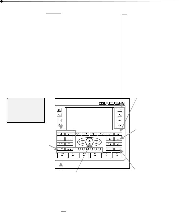
Front panel tour—left side
Meters
Each track has its own 10-segment, peak-reading meter. |
TRACK BUTTONS 1-24: these are most often |
||
When it turns yellow, you have 6 dB or less of |
used to arm a track for recording, but they |
||
headroom left. At the top, the red CLIP warns you of |
are also used to select tracks for editing. |
||
the onset of clipping. |
TRACK EDIT: Hold this while pressing a TRACK |
||
|
|
||
If a track's meter is surrounded by a lit rectangle, that |
button to select a track for editing. |
||
|
|||
|
track is currently selected for editing. See page |
PEAK MODE: This sets how the |
|
|
55. |
meter will display peaks: |
|
|
|
||
|
|
continuously holding them until |
|
REC INDICATORS: These indicate when a track is |
PEAK CLEAR is pressed, holding |
||
peaks on the meter for a few |
|||
"armed" for recording (flashing) or in record (solid), |
moments, or not hold them at all. |
||
as controlled by TRACK BUTTONS 1-24. |
For more about the meters and |
||
INPUT INDICATORS: These indicate when a track |
level setting, see Chapter 3: Basic |
||
Recording and Playback. |
|||
is monitoring its input (indicator ON), as |
|||
|
|||
controlled by the AUTO INPUT, ALL INPUT buttons |
Drive |
||
in combination with whether the track is armed. |
|||
caddies: |
|||
See page 40 for details. |
|||
The ADAT |
|||
DRIVE 1, DRIVE 2: Use these buttons to select or |
|||
HD24 records |
|||
unmount (power down) a drive. The LED beneath |
on removable, |
||
it indicates the state of |
affordable IDE |
||
the drive: |
hard drives. It |
||
• If the LED is |
comes sup- |
||
plied with a 10- |
|||
|
off, the drive is |
gigabyte drive |
|
|
unmounted (or |
in the DRIVE 1 |
|
|
empty) and |
slot, which |
|
|
may be |
gives you 45 |
|
|
removed. |
minutes of 24- |
|
• |
LED green: the |
track recording |
|
|
drive is |
time (1080 total |
|
|
mounted. |
track minutes). |
|
• |
LED red: the |
The DRIVE 2 |
|
slot comes with an empty caddy, which you can fill |
|||
|
drive is currently |
||
|
with an IDE drive of any size, from almost any |
||
|
being accessed for |
||
|
manufacturer (see your Alesis dealer for details). |
||
|
recording or |
||
|
Additional drive caddies are available from your |
||
|
playback. |
||
|
Alesis dealer, so you can instantly swap out |
||
ÖTo see which drive is |
|||
projects, just as conveniently as tape. |
|||
|
|||
selected, look at the icons |
|
||
next to the HD Free Space |
Never pull a drive caddy out unless its LED is |
||
display. See page 49. |
|||
off! Doing so could physically damage the |
|||
|
POWER (SOFT): Once the |
||
|
drive or corrupt data on it. |
||
|
"hard" POWER switch on the |
For more information about drive caddies, see Chapter 5: |
|
|
rear panel is ON, push this to |
||
|
turn the unit on and off. |
Working with Drives. |
|
14 |
ADAT HD24 Reference Manual |
chapter 1 • quick start guide
Front panel tour—right side
Editing buttons
The EDIT START and EDIT END buttons define a region of a track (or tracks, as determined by the TRACK EDIT button) that can be selected for editing. Press CUT to remove the region (leaving silence on the track), and COPY to copy it without removing it. PASTE pastes the audio that was cut or copied starting at the EDIT IN point, overwriting data on the selected track(s). If you decide the edit you made was a mistake, press UNDO to go back to the way it was.
Display buttons
These buttons relate to the icons at the bottom of the display. INPUT SELECT toggles between analog or digital input. CLOCK SOURCE selects whether the HD24's sample rate will be set by the INTernal clock, the WORD IN jack on the back panel, or the OPTICAL input.
If the clock is internal, SAMPLE RATE allows you to select the sample rate (44.1, 48, 88.2, or 96 kHz). LOCATE SELECT, along with the cursor keys below, allows you to select which of the current Song's 24 locations will be accessed when you press the LOCATE key.
You can UNDO only edit operations. Recordings and overdubs can't be undone.
S e e Chapter 6: Editing for detailed information on editing in the ADAT HD24.
Locate/auto buttons allow you to instantly access seven different locations in the current Song: LOCATE 0 returns to the zero point, while LOCATE 1-6 instantly locate to those points stored
in memory. SET LOCATE records the current location in the next locate point (above that shown in the display). When AUTO PLAY is on, the HD24 will automatically start playing when a locate point is reached. The LOCATE key sends the HD24 to the location currently shown in the bottom of the display.
See Chapter 4: Using Locate Points for details.
CURSOR buttons: YES (▲), NO
(▼), < and > control whatever is currently shown the middle of the display—selecting songs, naming them, answering questions. See the next page for examples of how these are used.
STOP, PLAY, RECORD work as they do on any recorder. Tap REW or FFWD to jump 5 seconds in either direction, or hold them to continue scanning.
Song buttons
Press SONG SEL to select any of 64 song locations to record or play back. NEW SONG initializes a blank song, allowing you to choose how many tracks it will have, etc. Use DEL SONG to delete a song from the hard drive, and NAME to name a song or locate point.
Special features
As long as the clock source display shows INT, PITCH allows you to speed up or slow down the playback or recording speed.
UTILITY is used for important housekeeping tasks such as setting the ISP address,
etc.
TRACK SLIP is an editing function that allows you to time-delay or advance any tracks up to 170 ms.
Press MIDI when you want to see the menus that control MIDI Time Code generation, MIDI Machine Control input, etc.
See Chapter 8: Synchronization and MIDI.
The AUTO RETURN and
AUTO RECORD buttons allow you to set up a "loop" so you can record a section over and over, until you get it right.
REHEARSE allows you to hear a punch in as if it were being recorded, without erasing it.
Details are covered in Chapter 4: Using Locate Points.
ADAT HD24 Reference Manual |
15 |

quick start guide • chapter 1
About the Display
Time counter
shows the current location (from the Song Start point, zero in ABS time) in hours, minutes, seconds, and frames.
Auto Icons
light whenever the
AUTO RECORD, AUTO PLAY, AUTO RETURN, or
REHEARSE functions are engaged.
HD FREE SPACE indicator shows how much recording time is available on the selected disk at the current track width and sample rate. The small yellow indicator to the left shows whether Drive 1 or Drive 2 is selected (it's 2 in this display)
The alphanumeric display:
This does different things, depending on what's going on at the time. In this example, it shows the current Song (number 01, titled "HD24".) On the second line, it's showing the length of the song: six minutes, 13 seconds, and 20 frames. It's also showing that this song has 24 tracks. As shown, the cursor (underline) is beneath the Song number,
Status icons
show the current settings controlled by the INPUT,
CLOCK SOURCE AND SAMPLE RATE (switches underneath the display) and the MONITOR icon shows the status of ALL INPUT AND AUTO INPUT (switches to the left of the display).
and pressing the YES (▲) button would change to Song 02. If a screen is asking a question (like, Delete Song?), you press YES (▲) or NO (▼) as you wish.
Locate point display:
Each Song has its own set of 24 Locate points. This shows you which one the HD24 will access if the LOCATE button is pressed. It also shows you if the point is being used as the START, END, punch IN or OUT point of one of the AUTO features.
See Chapter 4: Using Locate Points for details.
Tracks available
(Not in all displays.) Shows how many tracks are available in the current Song—in this case, all 24. Tracks take up disk space even if they're not recorded, so don't initialize a song with more than you need.
See page 30 for information on setting the track count of a song.
Write-protect status
(Not in all displays.) An icon of a locked padlock will appear in songs that have been protected from changes. An unlocked padlock icon will appear in songs that are NOT writeprotected.
16 |
ADAT HD24 Reference Manual |

chapter 1 • quick start guide
Rear panel tour
AC connector
This is where a standard IEC detachable power cord plugs in.
POWER switch (hard)
Normally, you'll leave this switch on, controlling power from the front panel switch.
Always turn off the unit using the front panel POWER switch first. The "soft" power-off procedure parks the drive heads, so they may be removed safely.
Ethernet
Connect this jack to a computer to transfer audio to any workstation. Each Song will appear as a folder containing each track as a separate .WAV or .AIFF file. Since the HD24 uses FTP, you can even connect this jack to a cable modem to transfer files over the Internet.
See Chapter 9: Ethernet.
Analog I/O
These INPUT and OUTPUT jacks may be connected to balanced or unbalanced mixers, since they're 3-conductor balanced 1/4” phone jacks (also called TRS for “tip-ring-sleeve”). See
Chapter 2: Connections.
Word clock input
Connect the word clock output of a digital mixer or master clock source to this jack, to ensure that everything in the studio samples at exactly the same time, avoiding ticks and clicks.
LRC and PUNCH
Connect the LRC remote control (supplied) to the LRC jack, and any momentary footswitch (optional) to the PUNCH jack for hands-free recording.
MIDI
MIDI IN allows the HD24 to follow MMC commands from a sequencer, and MIDI OUT can transmit MMC and MTC (MIDI
Time Code). See Chapter 8: Synchronization and MIDI.
ADAT Optical (Digital I/O)
Each of these connectors carries 8 channels of digital audio information (or, 4 channels at the 88.2/96 kHz sampling rate).
See Chapter 2: Connections.
ADAT Sync
Connect a remote control (such as the BRC™) to the SYNC IN jack. Or, connect a 9-pin cable from the SYNC OUT jack of another ADAT unit here to expand a system to as many as 120 simultaneous tracks. See
Chapter 8: Synchronization and MIDI and Chapter 2: Connections.
ADAT HD24 Reference Manual |
17 |

quick start guide • chapter 1
18 |
ADAT HD24 Reference Manual |

chapter 2
Connections
Unpacking and Inspection |
Installing in a Rack |
Your ADAT HD24 was packed carefully at the factory. The shipping carton was designed to protect the unit during shipping. Please retain this container in the highly unlikely event that you need to return the HD24 for servicing.
The shipping carton should contain the following items:
•ADAT HD24 with the same serial number as shown on shipping carton
•Power cable
•LRC remote control unit
•This reference manual
•Two drive caddies, one with an installed hard drive
•Stick-on rubber feet for table top installation
•Alesis warranty card
It is important to register your purchase; if
you have not already filled out your warranty card and mailed it back to Alesis, please take the time to do so now.
Mounting on a Shelf or Non-Rack Enclosure
To mount the HD24 on a shelf or other flat surface, Alesis recommends attaching the included stick-on feet to the deck’s bottom to avoid scratching the shelf’s surface.
Please observe the general comments on thermal considerations given under “Thermal Considerations in Rack Mounting” no matter where or how the deck is mounted.
The ADAT HD24 may be simply set on a table, or installed in a standard 19” audio equipment rack. The rack ears are integral to the unit.
The ADAT HD24 has a small cooling fan that
vents towards the rear of the unit. Make sure this outlet is not blocked. Make sure the rack itself has ventilation of the rear area.
Thermal Considerations in Rack Mounting
The HD24 can be mounted in an equipment rack (taking up 3 rack spaces) or placed on a table or shelf. When you install it, keep in mind that heat is the major enemy of electronic equipment. Please observe the following:
•The HD24 is designed to perform properly over a range of ambient temperatures from 10° C to +40° C (50° F to 104° F), in up to 80% noncondensing humidity. These are not absolute limits, but Alesis cannot guarantee that the HD24 will meet its published specs or remain reliable if operated outside of these ranges.
•Always allow adequate ventilation behind the HD24. Do not seal any enclosure that holds the HD24. It is not necessary to leave an empty rack space above or below the HD24 unless it runs hot enough to affect equipment above or below it. If your environment is unusually warm and not air conditioned, space between units will help the units run cooler.
•Do not attach the stick-on feet to the bottom of the HD24 if it will be rack-mounted.
ADAT HD24 Reference Manual |
19 |
connections • chapter 2
Power
Make sure you read the initial Important Safety Instructions chapter at the front of this manual.
AC Power Hookup
With the POWER switch on the REAR PANEL of the ADAT HD24 turned OFF, plug the female end of the power cord into the HD24’s POWER INPUT socket and the male (plug) end into a good quality, noise-free AC power source of the proper rating.
It’s good practice to not turn on the HD24 until all other audio cables are hooked up as well. Make sure your amplifier or powered speakers are switched off when turning the HD24 on or off to avoid damage.
The ADAT HD24 works with any standard line voltage from 90 to 240 volts and comes with a detachable AC line cord suitable for the country to which the unit is shipped.
AC Grounding
The line cable is an IEC-spec AC power cable designed to be connected to a grounded 3-pin outlet, with the third, round pin connected to ground. Do not substitute any other type of AC cord; IEC-spec cables of various lengths may be purchased from electronics stores or your Alesis dealer.
The ground connection is an important safety feature designed to keep the chassis of electronic devices such as the ADAT HD24 at ground potential. Unfortunately, the presence of a third pin does not always indicate that an outlet is properly grounded. You may use an AC line tester to determine this. If the outlet is not grounded, consult with a licensed electrician. When AC currents are suspected of being highly unstable in VAC and Hz, a professional power conditioner should be used.
Do not operate any electrical equipment with ungrounded outlets. Plugging the ADAT HD24 into an ungrounded outlet, or “lifting” the unit off ground with a three-to-two wire adapter, can create a hazardous condition. Alesis cannot be responsible for problems caused by using the ADAT HD24 or any associated equipment with improper AC wiring.
To use the ADAT in another country:
The ADAT HD24 has what's called a "switching power supply". That means it works with any AC voltage from 90 to 250 volts, 50 to 60 Hz. This eliminates the need for transformers or voltage switches when you travel from country to country. Your HD24 was supplied with the correct power cord for your country or local area. If you plan to travel with it to another country, obtain an IEC-spec AC power cable compatible with the outlets used in the other country and use it in place of the supplied cable. The following alternative power cords are approved for use with it:
•For 90-120 VAC 50/60 Hz operation in the US, Canada and/or Japan, use Alesis UL/CSA power cord #7-41-0001.
•For 240 VAC 50 Hz operation in England, use Alesis Power cord #7-41-0004.
•For 220 VAC 50 Hz operation in Europe and Scandinavia, use Alesis EU power cord #7-41- 0002.
•For 240 VAC 50 Hz operation in Australia, use Alesis AS power cord #7-41-0003.
Do you hear an AC hum in your system?
For detailed tips on how to get rid of "ground loops" that cause hum, see page 92.
20 |
ADAT HD24 Reference Manual |

chapter 2 • connections
Analog inputs and outputs
When connecting audio cables and/or
turning power on and off, make sure that all devices in your system are turned off and the volume controls are turned down.
Outputs from the HD24 to a mixing console:
Balanced outputs
The ADAT HD24's 24 analog OUTPUTS should be connected to the balanced line inputs or "tape inputs" of a recording console.
The line inputs of most modern consoles are designed to accommodate a three-conductor TRS (tip-ring-sleeve) 1/4" phone jack, (non-military type) as shown below:
Unbalanced Line Input
Signal 

 Tip
Tip
Ground |
|
Sleeve |
|
|
|
|
|
|
|
|
|
Tip |
 Sleeve
Balanced Line Input
Hot |
|
|
Tip |
|
Cold |
|
|
Ring |
|
Ground |
|
|
Sleeve |
|
|
|
|||
|
|
|
|
|
|
|
|
|
|
Tip |
|
Ring |
Sleeve |
This is the same connector used in the ADAT HD24. Obtain 24 channels of 3-conductor TRS 1/4"-to-1/4" cable, and connect the outputs of the HD24 to the inputs of the console.
Unbalanced outputs
You may use two-conductor 1/4" phone cables if your mixer doesn't have balanced inputs. In some cases, the mixer may have "RCA/Phono" inputs. In this case, obtain adapter cables.
Tip: Label or color-code cables wherever possible. With 48 different I/O connections, you don't want to guess. "Snakes" (multipair cables) are a good idea; you can get them in 8, 16, and 24-channel versions. Some have numbers written on the wire so you can tell one cable from another.
Others use different colors of wire. If so, use an acronym to keep the colors in order (like "Roy G. Biv" stands for red-orange-yellow-green- blue-indigo-violet in the order 1-2-3-4-5-6-7- 8). Use the same color order for the inputs and the outputs.
If you're using snakes, make sure you label (with a marking pen on tape, or with a commercial label machine) which are the inputs, which are the outputs, and which tracks they go to. Someday, you'll be glad you took the time.
If the mixer has XLR line inputs:
First of all, make sure that the XLR inputs are for “tape returns”. XLR inputs on most consoles are intended for microphone-level signals, not line-level inputs. However, if the line or tape inputs of the console use XLR connectors, you'll need to obtain an XLR-to-TRS (1/4") cable assembly. These are wired as shown below:
Sleeve (Ground) |
Tip (+) |
Pin 1 (Ground) |
Pin 2 (+) |
Ring (-) |
Pin 3 (-)
Don't use line transformers: Many XLR-to-1/4" adapters sold at electronics stores are NOT adapters, but transformers (and very low quality transformers at that). Don't use these on the output of the ADAT HD24—they're unnecessary and generally sound awful because they don't have the headroom to handle the ADAT HD24's output. Get a hard-wired adapter or cable from your professional audio dealer, or make one yourself from components.
ADAT HD24 Reference Manual |
21 |
connections • chapter 2
From the console to the HD24's inputs:
What's INPUT NORMALLING?
Most affordable analog consoles don't have 24 outputs. Even those with 24 or 32 tape inputs usually have only eight busses or group outputs. Luckily, the HD24 is designed so it can still be used with eight, four, or even two-bus consoles, thanks to a feature called input normalling that allows signal from the console plugged into one track to appear at others. For example, if you have an 8-bus console, simply connect from the bus/group outputs to the first 8 tracks of the ADAT HD24. Signal from the first input will appear at tracks 1, 9, and 17 without forcing you to repatch any cables, once you set the INPUT NORMALLING feature.
To connect from the group outs of a mixer:
You can choose between five different Input Modes: 2-Input Mode, 4-Input Mode, 8-Input Mode, 12Input Mode, and 24-Input Mode. These can provide five different analog audio input hookup options:
•2 Bus Mixer: Connect the mixer’s two bus outputs to the HD24’s INPUTS [1] and [2]. Select 2-Input Mode on the HD24 by holding down the INPUT SELECT button until the display reads:
Select Audio
Input Tracks
Then press either Track Select buttons [1] or [2]; notice that the INPUT LEDs for tracks 1 and 2 remain lit until you release the INPUT SELECT button.
•4 Bus Mixer: Connect the mixer’s four bus outputs to the HD24’s INPUTS [1] through [4]. Select 4-Input Mode by holding down the INPUT SELECT button until you’re prompted to select
the tracks; press either Track Select buttons [3] or [4]. The INPUT LEDs for tracks 1 through 4 remain lit until you release the INPUT SELECT button.
•8 Bus Mixer/Direct Outputs: Connect the mixer’s eight bus outputs (or 8 direct outputs) to the HD24’s INPUTS [1] through [8]. Select 8-Input Mode by holding the INPUT SELECT button and pressing any Track Select
button from [5] - [8]. The INPUT LEDs for tracks 1 through 8 remain lit until you release the
INPUT SELECT button.
•12 Bus Mixer: You’ve got the drill by now, right? When the display reads “Select Audio Input Tracks”, press a Track Select button between 9 and 12, and the lower inputs will “normal” to the higher tracks (1 to 1 and 13, 2 to 2 and 14, etc.)
•24 Bus Mixer (or Direct Outs): Same deal—press INPUT SELECT and press a track 13 or above to have the “normal” setup with each track “hearing” its own separate input.
In the first four modes, the HD24 internally connects the inputs to the higher tracks (for example, Input 1 goes to tracks 1, 9 and 17 in 8- Input mode).
22 |
ADAT HD24 Reference Manual |

chapter 2 • connections
|
About Audio Cables |
|
|
|
Typical input jack hookups |
|
|
||||||||||
|
The connections between the ADAT HD24 and your |
|
|
The inputs of a multitrack recorder are typically |
|||||||||||||
|
studio are your music’s lifeline, so use only high |
|
|
hooked up in one of three ways: |
|
|
|
||||||||||
|
quality cables. These should be low-capacitance |
|
|
• |
From |
the |
console’s |
"direct outs" |
|||||||||
|
shielded cables with a stranded (not solid) internal |
|
|
||||||||||||||
|
|
|
|
(sometimes |
labeled |
"tape |
outs". |
||||||||||
|
conductor and a low-resistance shield. Although |
|
|
|
|||||||||||||
|
|
|
|
This patches one channel of the mixer directly |
|||||||||||||
|
quality cables cost more, they do make a difference. |
|
|
|
|||||||||||||
|
|
|
|
to one track of the recorder, bypassing most |
|||||||||||||
|
|
|
|
|
|
|
|
|
|||||||||
¾ Route cables to the HD24 correctly by |
|
|
|
mixer circuitry. This is preferred when the |
|||||||||||||
|
|
|
signals going to tape require none of the mixer’s |
||||||||||||||
|
observing the following precautions: |
|
|
|
features (effects, grouping, routing, etc.). |
||||||||||||
|
• Do not bundle audio cables with AC power |
|
|
• |
From |
the |
mixer's |
"bus" or |
"group" |
||||||||
|
|
|
|
outputs. You can use the mixer for grouping, |
|||||||||||||
|
cords. |
|
|
|
|
|
|
|
|||||||||
|
|
|
|
|
|
|
|
premixing, effects, etc. This puts more circuitry |
|||||||||
|
• Avoid running audio cables near sources of |
|
|
|
|||||||||||||
|
|
|
|
between the sources and the HD24, although |
|||||||||||||
|
electromagnetic |
interference |
such as |
|
|
|
since most routing can be done at the mixer, |
||||||||||
|
transformers, monitors, computers, etc. |
|
|
|
you’ll seldom need to do any repatching. |
||||||||||||
|
• Do not place cables where they can be stepped |
|
|
• From |
a combination of direct |
||||||||||||
|
on. |
Stepping on |
a cable may not cause |
|
|
|
outputs |
and |
bus |
outputs. |
Some |
||||||
|
immediate damage, but it can compress the |
|
|
|
situations require a combination of the two |
||||||||||||
|
insulation between the center conductor and |
|
|
|
approaches, especially if you're recording a lot |
||||||||||||
|
shield (degrading performance) or reduce the |
|
|
|
of tracks at once and your mixer has only 8 |
||||||||||||
|
cable’s reliability. |
|
|
|
|
|
group outputs: |
|
|
|
|
|
|||||
|
• Avoid twisting the cable or having it make |
|
¾ Example: |
|
|
|
|
|
|
|
|
||||||
|
sharp, right angle turns. |
|
|
|
Here's a typical arrangement that might be used on |
||||||||||||
|
• Never unplug a cable by pulling on the wire |
|
|
||||||||||||||
|
|
|
a live tracking session, cutting basics for a full band |
||||||||||||||
|
itself. |
Always unplug by firmly grasping the |
|
|
plus two "guide vocals": |
|
|
|
|
||||||||
|
body of the plug and pulling directly outward. |
|
|
|
|
|
|
|
|
|
|
|
|
||||
|
|
|
|
|
|
|
|
|
|
|
|
|
|
|
|||
|
|
|
|
|
|
|
|
Mic |
|
|
Mixer out |
Track |
|
|
|||
|
|
|
|
|
|
|
|
Kick |
|
|
Direct out |
1 |
|
|
|||
|
And most importantly, keep connectors |
|
|
|
|
|
|
||||||||||
|
|
|
Snare |
|
|
" |
|
|
2 |
|
|
||||||
|
clean. |
Every few months, unplug them and |
|
|
|
|
|
|
|
|
|||||||
|
wipe off oxidation with a clean cloth soaked in |
|
|
Snare bottom |
|
" |
|
|
3 |
|
|
||||||
|
alcohol or contact cleaner. Insert the plugs in |
|
|
|
|
|
|
|
|
|
|
|
|
||||
|
|
|
Hi-hat |
|
|
" |
|
|
4 |
|
|
||||||
|
the jacks a few times, to clean the internal jack |
|
|
|
|
|
|
|
|
||||||||
|
|
|
Tom 1 |
|
|
Group 1-2 |
5-6 (pan left) |
||||||||||
|
contacts. |
Although Alesis does not endorse |
|
|
|
|
|||||||||||
|
any specific product, certain chemicals, when |
|
|
Tom 2 |
|
|
" |
|
|
5-6 (left-center) |
|||||||
|
applied to electrical connectors, are claimed to |
|
|
|
|
|
|
|
|
|
|
|
|
||||
|
|
|
Tom 3 |
|
|
" |
|
|
5-6 (right-center) |
||||||||
|
improve the electrical contact between |
|
|
|
|
|
|
||||||||||
|
|
|
Tom 4 |
|
|
" |
|
|
5-6 (pan right) |
||||||||
|
connectors. Avoid oily products that actually |
|
|
|
|
|
|
||||||||||
|
attract more dirt. |
|
|
|
|
Overhead left |
|
Direct out |
7 |
|
|
||||||
|
|
|
|
|
|
|
|
|
|
|
|||||||
|
|
|
|
|
|
|
|
Overhead right |
|
Direct out |
8 |
|
|
||||
|
|
|
|
|
|
|
|
Bass |
|
|
" |
|
|
9 |
|
|
|
|
The ADAT HD24 is wired according to the modern |
|
|
Guitar |
|
|
" |
|
|
10 |
|
|
|||||
|
|
|
Piano |
|
|
Group 3-4 |
11-12 (stereo) |
||||||||||
|
standard of “Pin 2 (tip) = Hot”. |
Some older |
|
|
|
|
|||||||||||
|
equipment was wired with Pin 3 hot; check to |
|
|
Digital synth |
|
" |
|
|
" |
|
|
||||||
|
make sure correct polarity is |
maintained |
|
|
|
|
|
|
|
||||||||
|
|
|
Analog synth |
|
" |
|
|
" |
|
|
|||||||
|
throughout your system. |
|
|
|
|
|
|
|
|
||||||||
|
|
|
|
|
|
|
|
Vocal 1 |
|
|
Direct out |
13 |
|
|
|||
|
|
|
|
|
|
|
|
|
|
|
|
|
|
|
|
|
|
|
|
|
|
|
|
|
|
Vocal 2 |
|
|
" |
|
|
14 |
|
|
|
ADAT HD24 Reference Manual |
23 |

connections • chapter 2
Even a 4-bus mixer could be used to record these 14 tracks.
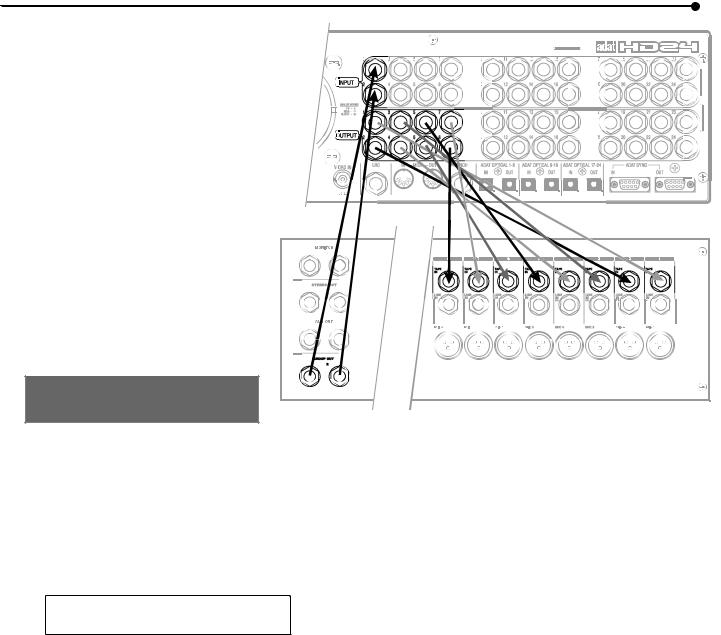
Sync In/Out
The two DB 9 connectors on the back panel marked SYNC IN and SYNC OUT are used for synchronizing two or more HD24s together, or a combination of HD24s and other ADATs, or a computer workstation using the ADAT/EDIT card or similar device. Up to five HD24s can be linked, making a 120-track system. This requires a male-to-male, 9- pin D connector cable for each additional machine in the chain.
Use only Alesis-approved Sync cables, available in various lengths from your dealer. Improper cables (such as those used for computers) may not function correctly.
In such a system, you are basically treating all connected machines as though they were a large multitrack unit. The first ADAT in the chain is called the “master”, and all other connected units are referred to as “slaves”. However, each slave can also be used independently when the master machine is stopped.
The Sync In and Out connections can also be used for synchronizing to SMPTE Time Code. See Chapter 8 for more information.
To synchronize multiple HD24s and/or ADATs:
1.Locate the SYNC IN and SYNC OUT connectors.
2.Connect one end of a male-to-male, 9-pin connector cable to the master’s SYNC OUT jack.
3.Connect the other end of the cable to the first slave’s SYNC IN jack.
4.For additional slaves, connect one end of a male-to-male, 9-pin D connector cable to the first slave’s SYNC OUT jack, and the other end to the second slave’s SYNC IN jack. Its SYNC OUT jack then connects to the third slave’s SYNC IN jack, and so on.
The moment the SYNC connection is made, the slave machine(s) will automatically switch to external clock and follow transport commands from the master (unless taken offline by dismounting all
drives, or ejecting tapes). For more information about using multiple HD24s and/or ADATs, refer to chapter 8.
The illustration below depicts an ADAT HD24 being used as the master machine to another HD24 so they can be synchronized together, making a 48track recorder.
24 |
ADAT HD24 Reference Manual |

chapter 2 • connections
ADAT Optical Digital Inputs and
Outputs
Each of the digital inputs and outputs of the ADAT HD24 carries eight tracks or channels (up to 48 kHz) on a single fiber optic cable in the industry-standard ADAT Optical format. To cover the 24 tracks of the HD24, there are three sets of inputs and three sets of outputs. Connect these outputs if you want to:
•copy audio between ADATs within the digital domain
•connect to a digital mixing console
•transfer audio to and from a computer workstation with ADAT Optical ports
•receive digital signals from many Alesis keyboards and effect devices
Digital copying requires three fiber optic cables for each HD24 in the system (or any other ADATcompatible product). Additional cables are available from your dealer in various lengths up to 16 feet. When connecting a digital mixer, you'll need six cables per HD24 in the system. Digital audio connections can be made while power is on or off. Note: To bounce tracks within a single HD24, it is not necessary to connect the optical network.
About 16-bit and 20-bit signal transfers
All data on the ADAT Optical cable has always been in a 24-bit word length; in earlier 16-bit ADATs the eight least significant bits are filled with zeroes, in 20-bit ADATs the last four bits are zeroes. If 24-bit data is sent to a 20-bit machine, the four “extra” bits are simply ignored, much as fractions of a penny don't matter when you actually pay your bill at the gas station. ADAT Type II machines (such as the M20, XT20, and LX20) can receive a full 20-bit transfer via the optical cables (if the tapes in those machines were formatted in 20-bit mode). The ADAT/EDIT system can receive a full 24-bit transfer, as can many other computer workstations.
If you have a digital mixer, you may need to upgrade its software or hardware to receive or generate true 24-bit signals via the ADAT Optical interface.
To transfer audio from the HD24 to non-24-bit systems you have two options:
1.Transmit at 24 bit, and the receiving unit will ignore the bits it can't read, essentially cutting them off. This option provides the lowest noise when tracks are going to be processed and mixed.
2.Connect the machines via analog inputs and outputs. This will effectively dither the 24-bit signal of the HD24 to whatever the receiver is using. While a digital transfer is theoretically best, today’s converters are of such high quality that the difference is usually not audible.
High sample rate operation
At the 88.2 and 96 kHz sample rates, the ADAT Optical format becomes essentially a 4-channel interface. See Chapter 7, "High Resolution Operation".
ADAT HD24 Reference Manual |
25 |

connections • chapter 2
To connect the digital inputs and outputs
1.Locate the DIGITAL IN and DIGITAL OUT connectors for Tracks 1-8.
Remove the connectors’ plugs (if present) and store for later use.
2.Remove the clear, plastic tube covering each end of the optical cable (if present). Connect one end of the fiber optic cable into the DIGITAL OUT 1-8 jack of the HD24.
The cable is non-polarized, so either end can be inserted into the optical output.
3.Connect the other end of the fiber optic cable to the ADAT Optical™ input for the first eight tracks of the receiver (mixer, computer interface, or ADAT).
Tip: if the machines are on, the cable from the source machine will show a red light at the end.
4.Repeat steps 2 and 3 for the DIGITAL OUT 9-16 and DIGITAL OUT 17-24 jacks.
At this point, you should be able to PLAY a song on the HD24 and hear it (or see the meters move) on the other unit.
5.Now, connect the outputs of the other device to the DIGITAL IN 1-8, DIGITAL IN 9-16 and DIGITAL OUT 17-24 of the HD24.
Only eight outputs on the other device?
In some cases, such as an 8-bus digital mixer without direct outputs, you may not need to connect to the DIGITAL IN 9-16 and DIGITAL IN 17-24 of the HD24. The HD24 can electronically "patch" a digital input from its first eight inputs to higher tracks if needed. See page 22.
The illustration below shows an HD24 connected to an 8-bus digital mixer. The mixer’s ADAT Optical outputs are connected to the HD24 Digital Inputs and the HD24’s Digital Outputs are connected to the mixer’s ADAT Optical Inputs.
26 |
ADAT HD24 Reference Manual |

chapter 2 • connections
Copying between ADATs
If you combine an ADAT HD24 with several ADATs in a system and aren't using a digital mixer, you may connect them directly so you can copy the HD24 to tape and the tapes to the HD24.
To digitally copy between an HD24 and tape-based ADATs, simply connect the DIGITAL OUTS of the HD24 machine to the DIGITAL INS of three different ADATs, and then the inputs to the outputs, as shown below. Connect the SYNC OUTS so the HD24 is last in the chain.
ADAT Optical hookups between two HD24s aren’t usually necessary—it’s faster to simply swap hard drives and make copies in a single machine.
Don’t loop the opticals: Unlike tape-based ADATs, the HD24 is not designed to be
connected in a digital loop; there is no “digital through” mode where one HD24 will simply “pass along” the digital signal at its input. The digital output of each HD24 simply represents whatever is on that particular machine.
|
|
|
|
|
|
|
|
|
|
|
|
|
|
|
|
|
|
|
|
|
|
|
|
|
|
|
|
|
|
ADAT HD24 Reference Manual |
27 |
||||

connections • chapter 2
Connecting to a computer interface card
This illustration shows an HD24 connected to an ADAT-compatible computer interface card. The card’s ADAT outputs are connected to the HD24 Digital Inputs and the HD24’s Digital Outputs are connected to the card’s ADAT Inputs. In this particular case the ADAT SYNC is connected so that the card (computer) is the master or controller of the ADAT HD24. Check with the manual for your computer interface for complete instructions.
28 |
|
|
|
|
|
|
|
|
|
|
|
|
|
|
|
|
|
ADAT HD24 Reference Manual |
|
|
|
|
|
|
|
|
|
|
|
|
|
|
|
|
|
||
|
|
|
|
|
|
|
|
|
|
|
|
|
|
|
|
|
||
|
|
|
|
|
|
|
|
|
|
|
|
|
|
|
|
|
||
|
|
|
|
|
|
|
|
|
|
|
|
|
|
|
|
|
||
|
|
|
|
|
|
|
|
|
|
|
|
|
|
|
|
|
||
|
|
|
|
|
|
|
|
|
|
|
|
|
|
|
|
|

chapter 2 • connections
Footswitches
The HD24 provides two footswitch connectors on its rear panel using 1/4" mono (T/S) jacks. One, labeled LRC, allows locate and play commands when used with a standard footswitch, or more elaborate control when used with the LRC Remote control; the other, labeled PUNCH, is for punch in/out control.
The two footswitch jack functions are designed to be used with any momentary single-pole/single- throw footswitch (either normally open or normally closed*). These should be plugged in prior to power-up so that the HD24 can configure itself for the type of footswitch being used.
When using a normally open footswitch, the
footswitch can be plugged in without restarting the HD24 (powering down and powering up). However, if using a normally closed footswitch, the HD24 should be restarted after plugging it in. Don’t step on the footswitch while the HD24 is being powered on, or the switch will operate “backwards”.
The LRC Remote
You can connect the compact “LRC” HD24 remote control unit to the LRC jack only to provide remote access of transport functions. Using the punch jack for an LRC does not work on the HD24. An ADAT LRC can also be used, but double-check the labeling of the buttons as these have changed for the HD24.
The Punch In/Out footswitch and HD24 Remote both work in conjunction with the Rehearse and Auto Record features. See Chapter 4, "Using Locate Points".
|
|
|
|
|
|
|
|
|
|
|
29 |
|
|
|
|
|
|
|
|
|
|
||
|
|
|
|
|
|
|
|
|
|
||
|
|
|
|
|
|
|
|
|
|
||
|
|
|
|
|
|
|
|
|
|
||
|
|
|
|
|
|
|
|
|
|
||
|
|
|
|
|
|
|
|
|
|
||
ADAT HD24 Reference Manual |
|||||||||||
 Loading...