


Reference Manual

This page intentionally left blank
10% |
20% |
30% |
40% |
50% |
60% |
70% |
80% |
90% |
100% |
||
|
|
|
|
|
|
|
|
|
|
|
|

Table Of Contents |
|
Introduction.......................................................... |
5 |
Welcome!...................................................................................................... |
5 |
About the MultiMix 8 FireWire ....................................... |
6 |
All-In-One Mixer and Multichannel Computer Audio |
|
Interface ....................................................................................................... |
6 |
MultiMix 8 FireWire Key Features........................................................... |
7 |
How to Use This Manual ................................................... |
8 |
A Few Words for Beginners.............................................. |
9 |
Chapter 1: Getting Started ................................ |
11 |
Hooking up the MultiMix 8 FireWire............................. |
11 |
Using Proper Cables .......................................................... |
12 |
Setting Levels ...................................................................... |
12 |
Chapter Two: A Tour of the MultiMix............. |
13 |
Patchbay............................................................................... |
13 |
Mic Inputs (Channels 1 – 4)...................................................................... |
13 |
Line Inputs (Channels 1 – 4)..................................................................... |
13 |
Line Inputs (Channels 5 – 8)..................................................................... |
14 |
PHONE Jack............................................................................................... |
14 |
AUX RETURNS ........................................................................................ |
14 |
AUX SENDS .............................................................................................. |
14 |
2-TRACK..................................................................................................... |
14 |
MAIN MIX OUT....................................................................................... |
14 |
CTRL RM OUT ......................................................................................... |
14 |
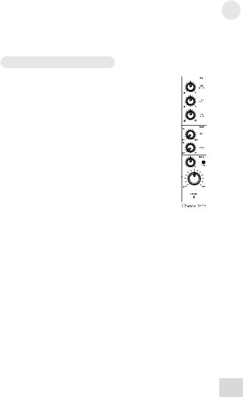
Channel Strips .................................................................... |
15 |
Level Control............................................................................................... |
15 |
PAN or BAL................................................................................................ |
15 |
PEAK LED................................................................................................. |
15 |
Aux................................................................................................................ |
15 |
EQ................................................................................................................. |
16 |
Master Section..................................................................... |
16 |
Main Mix...................................................................................................... |
16 |
2TK To Mix................................................................................................. |
16 |
HDPH / CTRL RM................................................................................... |
16 |
2TK TO CTRL ROOM Switch ............................................................... |
17 |
AUX RETURN A LEVEL....................................................................... |
17 |
EFFECTS / AUX RET B LEVEL ......................................................... |
17 |
LED Meters................................................................................................. |
17 |
POWER Indicator...................................................................................... |
17 |
+48V Indicator ........................................................................................... |
17 |
Rear of the Mixer................................................................ |
18 |
Power Input ................................................................................................. |
18 |
Power Supply Unit...................................................................................... |
18 |
Power On ..................................................................................................... |
18 |
Phantom On................................................................................................ |
18 |
Firewire ports .............................................................................................. |
18 |
1

Table Of Contents |
|
Chapter Three: Digital Effects |
|
Processor ............................................................... |
19 |
Effects Section Components ............................................ |
19 |
Program Selection Knob ........................................................................... |
19 |
LED Display................................................................................................ |
19 |
CLIP Indicator ............................................................................................ |
19 |
SIG Indicator .............................................................................................. |
19 |
Effect Descriptions............................................................. |
19 |
HALL ........................................................................................................... |
19 |
ROOM ......................................................................................................... |
19 |
PLATE ......................................................................................................... |
19 |
CHAMBER ................................................................................................. |
19 |
CHORUS..................................................................................................... |
20 |
FLANGE..................................................................................................... |
20 |
DELAY ........................................................................................................ |
20 |
PITCH.......................................................................................................... |
20 |
MULTI & MULTI II.................................................................................. |
20 |
Chapter Four: Traditional Mixing................... |
21 |
Simple Live Setup............................................................... |
21 |
Using Additional External Audio Sources.................... |
21 |
Simple Two-Channel Recording Setup |
|
(without Firewire).............................................................. |
22 |
Chapter Five: Firewire Recording .................. |
23 |
First-time connection instructions................................. |
23 |
and driver installation ...................................................... |
23 |
Installing the optional applications............................... |
24 |
Power-on/Power off order ................................................ |
24 |
Power-on sequence..................................................................................... |
24 |
Power-off sequence.................................................................................... |
24 |
Firewire inputs and outputs............................................ |
25 |
Channels sent from the MultiMix to the computer............................... |
25 |
Channels returned from the computer to the MultiMix....................... |
25 |
Sound setup under Windows ........................................... |
26 |
Disabling Windows System Sounds................................ |
28 |
Connections and settings for Firewire |
|
recording and monitoring ................................................ |
29 |
Using the MultiMix FireWire with Cubase |
|
and other ASIO applications............................................ |
29 |
Choosing the MultiMix as your audio device ......................................... |
30 |
Creating a new audio file ........................................................................... |
34 |
Working with the ASIO control panel............................ |
38 |
Accessing the ASIO control panel........................................................... |
38 |
Setting the mixer nickname ....................................................................... |
38 |
Setting the master device ........................................................................... |
38 |
Adjusting latency by changing the buffer size ........................................ |
39 |
Adjusting the sample rate .......................................................................... |
39 |
2

Table of Contents |
|
Using the MultiMix FireWire with Sonar |
|
and other WDM applications ........................................... |
40 |
Choosing the MultiMix as your audio device ......................................... |
40 |
Assigning inputs to audio tracks............................................................... |
43 |
Using the MultiMix FireWire with |
|
CoreAudio on the Macintosh ........................................... |
44 |
Chapter Six: Troubleshooting: non- |
|
Firewire ................................................................. |
45 |
Chapter Seven: Troubleshooting: |
|
Firewire ................................................................. |
49 |
Computer or audio application does not see |
|
the MultiMix FireWire....................................................... |
49 |
Basic troubleshooting................................................................................. |
49 |
Advanced troubleshooting under Windows ........................................... |
49 |
Audio playback or recording is at the wrong |
|
speed...................................................................................... |
51 |
Audio playback or recording stutters or |
|
drops out............................................................................... |
51 |
Audio echoes during recording....................................... |
51 |
Chapter Eight: Specifications........................... |
53 |
Chapter Nine: Block Diagram........................... |
55 |
Glossary ................................................................. |
57 |
Contact Information ........................................... |
59 |
Alesis Contact Information....................................................................... |
59 |
Trademarks .................................................................................................. |
59 |
3

Table Of Contents
This page intentionally left blank.
4

Introduction
Welcome!
Thank you for making the Alesis MultiMix 8 FireWire a part of your studio. Since 1984, we've been designing and building creative tools for the audio community. We believe in our products, because we've heard the results that creative people like you have achieved with them. One of Alesis' goals is to make high-quality studio equipment available to everyone, and this Reference Manual is an important part of that. After all, there's no point in making equipment with all kinds of capabilities if no one explains how to use them. So, we try to write our manuals as carefully as we build our products.
The goal of this manual is to get you the information you need as quickly as possible, with a minimum of hassle. We hope we've achieved that. If not, please drop us an email and give us your suggestions on how we could improve future editions of this manual.
We hope your investment will bring you many years of creative enjoyment and help you achieve your musical goals.
Sincerely,
The people of Alesis
For more effective service and product update notices, please register your MultiMix 8 FireWire online at:
http://www.alesis.com/ support/warranty.htm
5

Introduction
About the MultiMix 8 FireWire
The MultiMix FireWire mixers are the latest in the large family of Alesis audio mixers and the second series that includes computer interfacing (following on the launch of the MultiMix USB mixers in 2004).
We’ve come a long way since introducing our first mixing console in 1989. Since that time audio technology has grown in leaps and bounds, pushing up quality and driving down prices. Only a few years ago, you wouldn’t have been able to buy a mixer with analog performance this powerful for such an affordable price, and the addition of multichannel computer audio interfacing would have been a pipe dream. Just take a look at the key features listed below, and you’ll see that you have just made an incredible addition to your home studio or live setup.
All-In-One Mixer and Multichannel Computer Audio Interface
The MultiMix 8 FireWire gives you just about everything you need to create polished, professional-sounding recordings and live mixes. When designing this unit, our goal was to give you as much control over your recordings and mixes as possible without requiring a wealth of extra equipment. That’s why we added tools like the digital effects processor and the mic preamps. And with a multitude of ways in which to connect other equipment and instruments, the MultiMix 8 FireWire offers endless possibilities.
The MultiMix FireWire is also a full-duplex, multichannel computer recording interface device. Not only can you record every channel independently, but you can also record the MAIN mix channels. To get you started with computer-based recording, we even include a well-specified Digital Audio Workstation (DAW) software program. With a multitude of ways in which to connect other equipment and instruments, the MultiMix FireWire offers endless possibilities.
Important: download the drivers from http://www.alesis.com onto a folder on your desktop or insert the software CD into your computer’s CD drive BEFORE you plug your MultiMix into your computer for the first time.
See page 23 for details.
6

Introduction
MultiMix 8 FireWire Key Features
Multichannel Firewire (IEEE 1394a) input and output
– routes each individual channel’s output, plus the MAIN outputs, through the FIREWIRE port, and receives two channels back from the computer, all in 24-bit, 44.1/48 kHz digital audio.
ASIO and WDM computer drivers – lets you use the MultiMix FireWire with the vast majority of digital audio workstation programs.
Clean and powerful preamps – up to 50dB of preamp gain for capturing quiet sources. Globally switched phantom power.
Stereo inputs – Two stereo pairs for connecting line-level instruments.
Internal digital effects processor with 100 preset effects and an easy-to-read display – includes a variety of reverbs, delays, choruses, flanges, a pitch transposer and multiple combinations of these.
3-band EQ per channel – a potent tool for sonically shaping each channel to get that perfect mix.
2 aux sends per channel – one can be used to access an external effects device; the other can be used either to access the MultiMix’s internal effects or to access a second external device.
Control room output level – provides control over the separate control room output.
2-track send and return – lets you mix your audio to tape or other media and to add a tape deck or CD player to the mix.
External power supply
7

Introduction
How to Use This Manual
This manual is divided into the following sections describing the various functions and applications of the MultiMix consoles. While it's a good idea to read through the entire manual once carefully, those having general knowledge about mixing should use the table of contents to look up specific functions.
Chapter 1: Getting Started shows you how to include the MultiMix in your audio setup for recording, computer interfacing, and live applications. We’ve included a hookup diagram, guidelines for which cables to use and the vital steps you must take to set levels properly.
Chapter 2: A Tour of the MultiMix describes the MultiMix piece by piece. This chapter also features diagrams of the mixer to help you find each component as you read about it.
Chapter 3: Digital Effects Processor explains the effects provided by the on-board digital effects processor. If you want to know what a certain effect will do to your sound before you select it, this is where you should look.
Chapter 4: Traditional Mixing outlines a number of scenarios in which you can use the MultiMix for live mixing and simple, non-Firewire based recording.
Chapter 5: Firewire Recording orients you to the MultiMix’s powerful Firewire recording features, including software installation and setup with common DAW programs.
Chapter 6: Troubleshooting can give you a hand if you’re experiencing problems with your mixer. You’ll find that most issues can be resolved simply and quickly with the push of a button.
Chapter 7: Specifications and Chapter 8: Block Diagrams are full of technical information for the more techie users.
And at the end of this manual you’ll see a glossary of common mixing-related terms.
Helpful tips and advice are highlighted in a shaded box like this.
When something important appears in the manual, an exclamation mark (like the one shown at left) will appear with some explanatory text. This symbol indicates that this information is vital when operating the MultiMix consoles.
8
Introduction
A Few Words for Beginners
We realize that some of you who have purchased the MultiMix 8 FireWire are fairly new to mixing, to computer-based recording, or both. We’ve written this manual with that in mind. We also designed the MultiMix 8 FireWire to be both powerful and easy enough to use that even a beginner can quickly pick up the basics.
Many mixer manuals—and manuals for just about any electronic instrument for that matter—are full of complicated terminology and incomplete instructions that presume a lot of experience on the part of the reader. We try to avoid that with this manual. True enough, you will find all the technical lingo and specifications you can handle in here, but we do our best to make this accessible to you.
Beginners will find several elements of this manual especially useful. Keep your eye out for the tips found in the gray boxes on the right side of the page. Be sure to check out the hookup diagrams on page 7, which will give you some ideas on how to fit the mixer into your audio setup after you’ve taken a tour of the mixer in Chapter 2. And if you come across any terms that you haven’t seen before, the glossary probably can help you out.
One of the most important things you’ll do before you begin a mixing or recording session is to set the levels. Be sure to refer to the instructions on page 16.
9

Introduction
This page intentionally left blank.
10

1 Getting Started
Hooking up the MultiMix 8 FireWire
This diagram will help you get the MultiMix 8 FireWire hooked up and ready to go. The equipment you use depends on personal preference and on whether you’re performing live or recording. For example, you’ll see below that the MAIN MIX OUT can be routed to a recording device for recording, to a PA system for live performance, or both.
Be sure to follow the guidelines for which cables to use (further down this page) and the procedure for setting levels (on the next page) before you begin mixing.
11

1 Getting Started
Using Proper Cables
When connecting instruments and other equipment to the MultiMix, it’s important that you use the appropriate types of cables. Here are some simple but important guidelines:
For the mic inputs, use XLR cables.
For the line inputs and all other 1/4” connections, use 1/4” mono TRS cables.
Use stereo RCA cables for the 2-track in and out.
Use a Firewire (IEEE 1394a) cable to connect one of the Firewire ports to a computer.
Setting Levels
Before you can begin mixing different audio sources with your MultiMix, you must set the level for each channel you’re using. This helps to prevent distortion and clipping. The idea is to get the strongest signal possible without clipping. Here’s how:
1.Turn the channel level control to the 12:00 position.
2.Turn the AUX SEND and GAIN controls all the way down, and turn the EQ knobs to the center detent (you’ll feel a click).
3.Connect the source of the signal to the channel’s input.
4.Play the instrument at a normal level and adjust the channel’s gain slowly until the PEAK LED lights.
5.Slowly reduce the channel’s gain until the PEAK LED no longer lights when you play.
6.If you need to apply EQ, do so and check the PEAK LED to make sure it still does not light as you play.
12

2 A Tour of the MultiMix FireWire
In this chapter, you’ll learn all about the MulitMix-8 FireWire’s components (except for the digital effects processor and computer connectivity, which are explained in later chapters). Please refer to the diagrams as you read each section to see which components we’re talking about.
Patchbay
At the rear portion of the top of the MultiMix 8 FireWire, you’ll find the patchbay. This is where you plug in instruments, signal processors, multitrack recorders and other devices. Whatever you need to connect to the mixer, this is where it’s done. In the following paragraphs, we tell you all about the inputs, outputs, switches and knobs you see in this section of the mixer.
Mic Inputs (Channels 1 – 4)
The MultiMix uses standard XLR-type mic inputs. These provide +48V phantom power that you can turn on and off with the Phantom On switch located on the rear of the mixer. You probably will have to turn on the phantom power when you’re using most condenser mics, as these usually require the extra voltage (unless the mic has its own power source, such as a battery). Dynamic and ribbon mics don’t require phantom power and are unaffected when the power is on.
These high-quality mic inputs also feature up to 50dB of preamp gain that you can adjust with the Gain knob.
Another useful feature of these mic inputs is a high-pass filter (HPF) that can be turned on and off with the HPF switch. When you activate this switch, all frequencies below 75Hz are cut from the signal. This is useful for mic or line signals that don’t have much bottom end, such as vocals, snares, cymbals and electric guitar. You’ll want to leave this inactivated for instruments like basses and kick drums.
Line Inputs (Channels 1 – 4)
The line inputs, marked LINE IN, are balanced 1/4” jacks that offer the same 50dB of preamp gain and the high-pass filter provided by the mic inputs (however, phantom power does not apply to line inputs). These inputs accept line-level instruments such as keyboards and drum machines. If you find that your instrument has a weak line signal, just plug it into channels 1 – 4 and crank it up with the Gain knob.
Although chances are your microphones will work fine with these mic inputs, we recommend that you do some checking up on the type of microphone you’re using, especially if it’s one of the older vintage models. Verify that your microphone requires phantom power and make sure its output is low impedance, balanced and floating.
Always connect your microphones before activating phantom power. Microphones tend to be very sensitive, and the sudden power surge can do permanent damage to the mic’s circuitry. It’s also a good idea to lower mixer levels before you activate phantom power.
13

2 A Tour of the MultiMix FireWire
Line Inputs (Channels 5 – 8)
Unlike channels 1 – 4, the line inputs on channels 5 – 8 are stereo inputs that have left and right inputs. If you’re using one of these channels as a mono input, plug your instrument into the left input. Channels 5 – 8 don’t have the extra gain found on channels 1 – 4 because most line-level instruments don’t require the extra boost. MIDI and other electronic instruments will work especially well on these channels. These inputs are also good for connecting CD players or tape decks, as these audio sources don’t require extra gain.
PHONE Jack
The headphone jack accepts 1/4” plugs. If your headphones are 1/8”, you can find a 1/8” to 1/4” adapter in most electronics stores.
AUX RETURNS
These are the 1/4” jacks where you connect the outputs of an external effects processor or other audio source. Each aux return gives you 15dB of gain that can be controlled by the AUX RET A and EFFECTS / AUX RET B LEVEL knobs in the mixer’s output section.
AUX SENDS
Use these jacks to connect the lines going out of the MultiMix into the input of an external effects processor. The aux sends give you 10dB of gain that can be controlled in the AUX section of each channel input.
2-TRACK
The 2-TRACK IN and OUT jacks are standard RCA jacks. You’ll use the OUTs for mixing to a tape deck or other recorder. With the INs you can bring in a signal, which can be monitored and even added to the main mix via the 2TK TO MIX switch in the master section of the mixer.
The 2-TRACK INPUT is blended with any signal coming back from a computer over the Firewire connection.
MAIN MIX OUT
These 1/4” jacks are where the signal on the main mix bus leaves the mixer. From there you can send it to a recorder or a PA system. The level of this signal is controlled by the MAIN MIX level control.
CTRL RM OUT
You can use these 1/4" jacks to send the control room signal to the input of the amplifier driving your monitors or headphones.
14
If you are using an effects device with only a mono output, plug it into the left return of STEREO AUX RETURN. It will appear in the center of the stereo spectrum, and not to the left.
A Tour of the MultiMix FireWire 2
This output usually carries the main mix. However, if you engage the 2TK TO CTRL ROOM switch, the CTRL RM OUT will carry the signal present at the 2-TRACK inputs.
Channel Strips
The eight channel strips are virtually identical to each other, with the only difference being that channels 1 – 4 are mono and channels 5 – 8 are stereo. Each channel strip contains the following components.
Level Control
The level control knob controls how much of the signal from the mic or line inputs is sent to the channel. To adjust the level, simply turn the knob to the desired level. In the leftmost position, levels are cut completely, and in the rightmost position you get an additional 10dB of gain.
PAN or BAL
This control—labeled PAN on the mono channels and BAL on the stereo channels—lets you assign the channel to a particular spot within the stereo spectrum. If you turn this knob to the left, you can hear the signal move to the left, and if you turn it to the right…you get the picture. The pan controls do this by adjusting the amount of the signal being sent to the left main mix bus versus the right main mix bus. The balance controls do it by controlling the relative balance of the left and right channel signals being sent to the left and right main mix buses.
PEAK LED
This indicator lets you know when the channel’s signal is clipping. This light plays an important role in setting channel levels by helping you know when to reduce the channel’s gain.
Aux
Here you’ll find knobs that control the levels of aux sends A and B. AUX A is pre-fader, which means that the AUX A send is affected only by the EQ and HPF settings. A pre-fader send is usually used for cue sends (for example, sending a signal to headphones while recording, for which you may not want the fader to alter the channel’s level).
AUX B is post-fader, which means that the AUX B send is affected by the fader (or level control knob in this instance), EQ and HPF settings. A post-fader send is generally used for sending the signal to an external effects device (so that the fader controls the signal level). Like AUX A, AUX B can be used for routing signals to external devices. And when you are using the onboard effects processor, AUX B is used to control the level of the channel’s signal being routed to the processor.
15

2 A Tour of the MultiMix FireWire
EQ
The MultiMix gives you three bands of EQ per channel. Using these knobs, you can tailor the channel’s signal by boosting some frequencies and cutting others. The LO and HI controls are shelving controls with fixed frequencies of 75 Hz and 12 kHz respectively. The MID control has a peaking response fixed at 2.5 kHz.
“Shelving” means that the mixer boosts or cuts all frequencies past the specified frequency. “Peaking” means that frequencies above and below the specified frequency fall off, forming a peak in a graphical representation.
Master Section
The Master Section is the heart of the mixer, where the channel inputs and aux returns all are mixed together and routed in various ways.
Main Mix
The signals from all channels and aux sends are sent to the main mix. The MAIN MIX level control is the one you’ll use to control the overall level of those combined signals. This knob affects the levels of the signals sent to the MAIN MIX OUT and the 2- TRACK OUT. In its leftmost position the signal is cut off completely, and in the rightmost position you get an additional 10dB of gain.
2TKTo Mix
When you press this switch, the signal coming in through the 2- TRACK IN gets routed to the MAIN MIX, joining whichever other signals are already part of the main mix. Used this way, the 2-TRACK IN effectively becomes another stereo channel (but without all the extras like pan, EQ, etc.).
HDPH / CTRL RM
The HDPH / CTRL RM knob controls the level of the signal being sent to the CTRL RM OUT and the PHONES output. The level of this signal is represented by the LED meters. The “CTRL RM” in the name of this knob refers to the fact that it controls the signal that typically is sent to the control room monitors of a studio, where someone—usually an engineer—is working the mixer. However, don’t be intimidated if you’re using this mixer in your bedroom, which probably isn’t equipped with a control room. In this scenario, you can use headphones or connect the CTRL RM OUT to your speakers.
16

A Tour of the MultiMix FireWire 2
2TKTO CTRL ROOM Switch
When you engage this switch, the signal coming in from the 2- TRACK jacks is routed to the headphones and to the control room output. This level is controlled by the HDPH / CTRL ROOM level control and cancels out any signal from the main mix.
AUX RETURN A LEVEL
This is the level control for the signal returning to the mixer via
AUX RETURN A.
EFFECTS / AUX RET B LEVEL
If you are using one of the MultiMix 8 FireWire’s internal effects, this knob controls the effect level. If AUX SEND B is connected to an external device, this knob controls the level for AUX RETURN B.
LED Meters
These are the two rows of yellow, green and red lights you see in the master section of the mixer. The LED meters allow you to view the signal level of the main mix and 2-TRACK IN depending on which signal you have routed to the control room mix.
POWER Indicator
When this LED is lit up, that means the POWER ON switch on the rear of the mixer has been activated.
+48V Indicator
When this one is lit up, that means the PHANTOM ON switch on the rear of the mixer has been activated and is supplying +48V phantom power to all XLR mic inputs.
17
 Loading...