


Configuration Guide
WDS Bridging and Antenna Installation
3CRWE725075
3CRWE825075A
3CRWE875075A
3CRWE885075A
The 3Com Access Point 7250/8250/8750/8850 supports WDS Bridging, which provides a flexible way to extend a wireless network. With WDS Bridging, you can increase your network to large, open locations where pulling wire is cost-prohibitive, restricted, or physically impossible.
This guide explains how to configure a WDS link between two 3Com access points, and describes some common installation scenarios for using WDS Bridging.
NOTE: For more information on the access points, including complete installation and configuration instructions, see the Wireless LAN Access Points User Guide included on the product CD in PDF format.
Understanding WDS Bridging Support
A Distribution System (DS) is a network (typically a wired network) that interconnects separate access points into a single LAN. With WDS, the interconnection no longer needs to be physically wired.
WDS uses the wireless medium to interconnect separate access points, thereby eliminating the cost and inconvenience that may hinder wire installations.
A WDS link can be used in a simple point-to-point link, a complex point-to-multipoint link, or a multilayer topology.
Point-to-Point WDS Link
The following example shows a point-to-point WDS link configured between two access points.
Wireless Desktops |
Wireless Desktops |
WDS Link
1

Point-to-Multipoint WDS Link
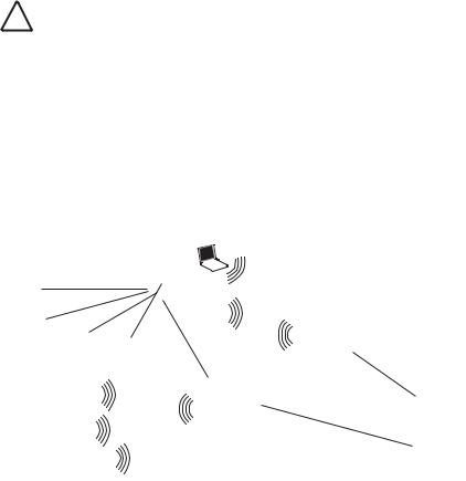
The following example shows point-to-multipoint WDS links configured between multiple access points.
Wireless Desktops
Point-to-Point WDS Link
Wireless Desktops
WDS Link
Wireless Desktops
WDS Link
WDS Security and Spanning Tree Support
For added security, the AP 8250 supports AES encryption over the WDS link. Additionally, Spanning Tree Protocol (STP) support prevents loops from being formed on the network. For more information on these items, see the Wireless LAN Access Points User Guide.
Configuring WDS Bridging
WDS Bridging can be configured in numerous ways. This section describes two common installation scenarios and the equipment required to complete the configurations:
Remote building wireless access with the AP8850
Remote building wireless access with the AP8250 and 802.11g Upgrade Kit
Configuration Guidelines
Before configuring the WDS settings, review the following guidelines:
The WDS link can be set up between 3Com access points only.
The pair of access points to be configured with a WDS link must be set to the same radio channel and SSID, and the link must be set up between 802.11a radios or 802.11g radios (that is, 802.11a to 802.11a or 802.11g to 802.11g).
The access points must be configured with security and standard access point settings before configuring the WDS link(s).
A Root Bridge can have a maximum of six Child Bridges assigned to it.
A Child Bridge can have a maximum of five Child Bridges assigned to it.
Antenna Guidelines
The 802.11a and 802.11g radios can be used with the following antennas in a bridging application:
802.11a radio: 3CWE591, 3CWE598, 3CWE596
802.11g radio: 3CWE491, 3CWE495, 3CWE498
2
Safety Guidelines
Only a licensed electrician with expert knowledge of outdoor installation and weather proofing techniques should perform an outdoor installation. Professional network personnel should oversee the entire installation. The importance of this is paramount, for the sake of compliance with local building codes, regulatory issues, and for the safety of people and equipment.
!CAUTION: Review the safety notices on page 9 before continuing.
Remote Building Wireless Access with the AP8850
This installation scenario describes one layer of bridging with one Root-Bridge and one Child Bridge. This scenario is common, for example, in schools or universities where students or professionals in remote buildings need secure, high-bandwidth wireless access.
In this configuration, an AP 8850 is installed and connected to the wired LAN and at each of the desired remote locations.
The bridge at the center of the network is configured as the Root Bridge with an omnidirectional antenna.
The remote bridges are configured as Child Bridges and use directional antennas, which are aimed at the Root Bridge antenna.
Child Bridge 1
Root Bridge
Child Bridge 2
The 802.11g radio at the remote location can be configured with any security configuration desired, including open security or full WPA security with 802.1X client authentication and AES encryption.
3
 Loading...