


 Loading...
ACCESSBUILDER
®REMOTE OFFICE 500 USER GUIDE
Part No. 980/000037/001
Published March 1996
3Com Corporation ■ 5400 Bayfront Plaza ■ Santa Clara, California ■ 95052-8145
© 3Com Sonix Ltd, 1996. All rights reserved. No part of this documentation may be reproduced in any form or by any means or used to make any derivative work (such as translation, transformation, or adaptation) without permission from 3Com Sonix Ltd.
3Com Sonix Ltd. reserves the right to revise this documentation and to make changes in content from time to time without obligation on the part of 3Com Sonix Ltd to provide notification of such revision or change.
3Com Sonix Ltd provides this documentation without warranty of any kind, either implied or expressed, including, but not limited to, the implied warranties of merchantability and fitness for a particular purpose. 3Com may make improvements or changes in the product(s) and/or the program(s) described in this documentation at any time.
UNITED STATES GOVERNMENT LEGENDS:
If you are a United States government agency, then this documentation and the software described herein are provided to you subject to the following restricted rights:
For units of the Department of Defense:
Restricted Rights Legend: Use, duplication or disclosure by the Government is subject to restrictions as set forth in subparagraph (c) (1) (ii) for restricted Rights in Technical Data and Computer Software clause at 48 C.F.R. 52.227-7013. 3Com Sonix Limited, Merchants’ House, Wilkinson Road, Cirencester, Gloucestershire, GL7 1YT United Kingdom.
For civilian agencies:
Restricted Rights Legend: Use, reproduction or disclosure is subject to restrictions set forth in subparagraph (a) through (d) of the Commercial Computer Software - Restricted Rights Clause at 48 C.F.R. 52.227-19 and the limitations set forth in 3Com Corporation’s standard commercial agreement for the software. Unpublished rights reserved under the copyright laws of the United States.
If there is any software on removable media described in this documentation, it is furnished under a license agreement included with the product as a separate document, in the hard copy documentation, or on the removable media in a directory file named LICENSE.TXT. If you are unable to locate a copy, please contact 3Com and a copy will be provided to you.
Unless otherwise indicated, 3Com registered trademarks are registered in the United States and may or may not be registered in other countries.
3Com, AccessBuilder, Boundary Routing,, LANplex, LanScanner, LinkBuilder, NETBuilder, NETBuilder II, Parallel Tasking, ViewBuilder, EtherDisk, EtherLink, EtherLink Plus, EtherLink II, SmartAgent, TokenLink, TokenLink Plus, TokenDisk and Transcend are registered trademarks of 3Com Corporation. 3TECH, CacheCard, FDDILink, FMS, NetProbe and Star-Tek are trademarks of 3Com Corporation. 3ComFacts is a service mark of 3Com Corporation.
Corporation. Novell and NetWare are registered trademarks of Novell Inc. Windows is a trademark of Microsoft Corporation. VT100 is a registered trademark of Digital Equipment Corporation.
Other brand and product names may be registered trademarks or trademarks of their respective holders.

IMPORTANT SAFETY INFORMATION
WARNING: Warnings contain directions that you must follow for your personal safety. Follow all instructions carefully.
Please read carefully and thoroughly the following information before installing the AccessBuilder 500:
■Exceptional care must be taken during installation and removal of the unit.
■If the power supply plug is unsuitable and you have to replace it, you may find other codings for the respective connections. Connect the power supply wires from the unit according to the following scheme:
■Brown wire to the Live (Line) plug terminal which may be marked with the letter L or colored red.
■Blue wire to the Neutral plug terminal which may be marked with the letter N or colored black.
■Yellow/green wire to the Earth (Ground) plug terminal which may be marked with the letter E, or the earth symbol or colored green/yellow. Do not connect the earth wire to any other pin.
■The safety status of the interconnection port on this equipment are as follows:
Ports identified by the labels VOICE and ISDN = TNV
Ports identified by the labels MANAGER, 10BASET, AUI and WAN = SELV
TNV (telecoms network voltage) is a circuit which under normal operating conditions carries telecommunication signals.
SELV (safety extra low voltage) is a secondary circuit which is designed and protected so that under normal and single-fault conditions, the voltage between any two accessible parts does not exceed a safe value (42.2 V peak or 60 V DC).
Only connect apparatus complying with the relevant interface requirements to the ports on this unit.

■There are no user-replaceable fuses or user-serviceable parts inside the unit. If you have a physical problem with the unit that cannot be solved with problem solving actions in this guide, contact your supplier.
■Disconnect the power before moving the unit.
WARNING: Twisted Pair RJ45 data port. This is a shielded RJ45 data socket. It cannot be used as a telephone socket. Only connect RJ45 data connectors to this socket.

WICHTIGE SICHERHEITSHINWEISE
ACHTUNG: Die Warnungen enthalten Anweisungen, die Sie zur eigenen Sicherheit zu befolgen haben.
Lesen Sie bitte die folgenden Informationen sorgfältig durch, bevor Sie den AccessBuilder 500 einbauen:
■Auf besondere Vorsicht muß während des Einund Ausbaus des AccessBuilder 500s geachtet werden.
■Falls Sie das beigelegte Stromversorgungskabel nicht verwenden können und zu ersetzen haben, finden Sie möglicherweise andere Anschlußbelegungen vor. Verbinden Sie die Stromversorgungskabel des Gerätes nach folgendem Schema:
■Braunes Kabel an Anschluß Phase welches normalerweise mit P und braunem Zuleitungskabel gekennzeichnet ist.
■Blaues Kabel an Anschluß Null, der mit N bezeichnet ist und normalerweise mit blauem Zuleitungskabel versehen ist.
■Gelbgrünes Kabel an Anschluß Erde, der mit dem Erdungssymbol markiert ist. Verbinden Sie niemals das Erdungskabel zu irgendeinem anderen Anschluß.
■Der Sicherheitsstandard der Anschlüsse fuer dieses Gerät sind wie folgt: Anschlüsse bezeichnet mit VOICE und ISDN = TNV
Anschlüsse bezeichnet mit MANAGER, 10BASET AUI und WAN = SELV
TNV (Telecoms Network Voltage - Spannung des Telekommunikationsnetzwerks) ist ein Anschluss, der unter normalen Umständen Telekommunikationssignale enthält .
SELV (Safety Extra Low Voltage - Extra Sicherheitsspannung) ist ein weiterer Anschluss, der unter normalen Umständen und

Fehlerkonditionen entworfen und gesichert wurde, so dass die Spannung zwischen zwei erreichbaren Teilen kein gefährliches Niveau erreicht (42.2V max. oder 60V DC).
An den Anschlussbuchsen der Geräte dürfen nur die dafür vorgesehenen Anschlüsse verwendet werden.
■Es sind keine von dem Benutzer zu ersetzende oder zu wartende Teile in dem Gerät vorhanden. Wenn Sie ein Problem mit dem AccessBuilder 500 haben, das nicht mittels der Fehleranalyse in dieser Anleitung behoben werden kann, setzen Sie sich mit Ihrem Lieferanten in Verbindung.
■Bevor der AccessBuilder 500 ausgebaut wird ist der Netzstecker zu ziehen.
ACHTUNG: gedrehte paarfache RJ45 Datenanschluss. Es ist eine abgeschirmte RJ45 Datenanschlußbuchse. Sie darf nicht als Telefonanschluß verwendet werden. Verbinden Sie nur RJ45 Datenstecker mit diesem Anschluss.

L’INFORMATION DE SÉCURITÉ
IMPORTANTE
AVERTISSEMENT: Les avertissements contiennent les instructions que vous devez suivre pour votre sécurité personnelle. Suivre toutes les instructions avec soin.
Veuillez lire à fond l’information suivante avant d’installer le moyeu:
■Le soin exceptionnel doit être pris pendant l’installation et l’enlèvement du moyeu.
■Si la prise du courant attachée au cordon d’alimentation n’est pas utilisable et il la faut remplacer, il est possible que vous trouverez que la couleur des fils du cordon d’alimentation peut ne pas correspondre avec les marques de couleur identifiant les bornes de votre prise de courant. Procéder comme suite:
■Le fil qui est coloré en marron doit être connecté à la borne de la prise du courant qui est indiquée par la lettre L ou par la couleur rouge.
■Le fil qui est coloré en bleu doit être connecté à la borne de la prise du courant qui est indiquée par la lettre N ou par le la couleur noire.
■Le fil de couleur vert et jaune doit doit être connecté à la borne qui est indiquée par la lettre E, ou par le symbol de terre ou colorée en vert et jaune. Ne connecter jamais ce fil à aucune autre borne de la prise du courant.
■Les normes de sécurité des ports d'interconnexion sur cet équipement sont les suivants:
Les ports marqués par les etiquettes VOICE et ISDN = TNV
Les ports marqués par les etiquettes MANAGER, 10BASET AUI et WAN = SELV

TNV (Telecoms Network Voltage - tension réseau de télécommunications) est un circuit qui dans des conditions d'opérations normales, transfert les signeaux télécoms.
SELV (Safety Extra Low Voltage - tension de sécurité extra-réduite) est un circuit secondaire désigné et protègé qui dans des conditions normales et de fautes uniques, assure que la tension entre deux éléments accessibles n'accedéra pas un niveau de sécurité (42.2V max. ou 60 V DC).
Connecter uniquement des unités conformes aux normes relatives des interfaces de cet équipement.
■Il n’y a pas de parties remplaceables par les utilisateurs ou entretenues par les utilisateurs à l’intérieur du moyeu. Si vous avez un problème physique avec le moyeu qui ne peut pas être résolu avec les actions de la résolution des problèmes dans ce guide, contacter votre fournisseur.
■Débrancher l’alimentation avant de remuer le moyeu.
AVERTISSEMENT: Le port de données RJ45 de paire tordue. Ceux-ci est un socle de données RJ45 blindé. Il ne peut pas être utilisé comme socle de téléphone. Seulement brancher les connecteurs de données RJ45 à ce socle.

CONTENTS
IMPORTANT SAFETY INFORMATION
WICHTIGE SICHERHEITSHINWEISE
L’INFORMATION DE SÉCURITÉ IMPORTANTE
ABOUT THIS GUIDE
|
Introduction |
1 |
|
|
|
|
|
How to Use This Guide 2 |
|
|
|
||
|
Conventions |
2 |
|
|
|
|
|
Additional Safety Information |
4 |
|
|
||
|
|
|
|
|
||
1 GETTING STARTED |
|
|
|
|||
|
Introduction |
1-1 |
|
|
|
|
|
AccessBuilder 500 Features |
1-1 |
|
|||
|
Benefits of ISDN 1-4 |
|
|
|
||
|
Using ISDN to Support Leased Line WAN Circuits |
1-5 |
||||
|
Pack Contents Checklist |
1-6 |
|
|
||
|
Registering Ownership Of Your AccessBuilder 500 |
1-7 |
||||
|
Pre-installation Requirements |
1-8 |
|
|||
|
AccessBuilder 500 Front and Rear Panel Features |
1-9 |
||||
|
Front Panel |
1-9 |
|
|
|
|
|
Front Panel Liquid Crystal Display 1-12 |
|
||||
|
Rear Panel |
1-13 |
|
|
|
|
Installation 1-16 |
|
|
|
|
|
|
|
|
Siting the AccessBuilder 500 |
1-16 |
|
|
|
||||
Connecting the Power |
1-17 |
|
|
|
|
|
||
Connecting to Your 10BaseT LAN |
1-18 |
|
|
|||||
Connecting to an Ethernet Hub |
1-18 |
|
|
|||||
Connecting to the In-House LAN |
1-19 |
|
|
|||||
Connecting to a Single Workstation |
1-20 |
|
|
|||||
Connecting to Your LAN Using a Transceiver |
1-20 |
|
||||||
Connecting to ISDN |
1-21 |
|
|
|
|
|
||
Connecting to the WAN |
1-22 |
|
|
|
|
|||
Connecting to the Voice Port |
1-22 |
|
|
|
||||
Connecting a Management Terminal 1-22 |
|
|
||||||
Quick Configuration |
1-24 |
|
|
|
|
|
|
|
Starting Quick Configuration |
1-24 |
|
|
|
||||
Example Using Windows 3.1 Terminal Application |
1-24 |
|||||||
About Quick Configuration 1-27 |
|
|
|
|
||||
Setting the Unit Name |
1-28 |
|
|
|
|
|
||
Connecting to a Novell (IPX) Network |
1-29 |
|
|
|||||
Connecting to an IP Host on the Same IP Network |
1-31 |
|||||||
Connecting to an IP Host on a Different IP Network |
1-33 |
|||||||
Connecting to the Internet or a PPP Router 1-35 |
|
|||||||
Monitoring ISDN Line Usage |
1-39 |
|
|
|
|
|||
Setting Up a WAN Link |
1-39 |
|
|
|
|
|
||
Examples of Typical ISDN Networking Applications |
1-41 |
|||||||
Novell Network |
1-41 |
|
|
|
|
|
|
|
IP Host on the Same IP Network |
1-43 |
|
|
|
||||
IP Host on Another IP Network |
1-44 |
|
|
|
||||
Internet or PPP Router |
1-46 |
|
|
|
|
|
||
Multiple Connections from a Single Site |
1-47 |
|
|
|||||
Troubleshooting 1-48 |
|
|
|
|
|
|
|
|
Renewing the Internal Protection Fuse |
1-50 |
|
|
|||||
Utilities Diskette |
1-51 |
|
|
|
|
|
|
Sub-directory NOVELL |
1-51 |
|
|||
|
Sub-directory MIB |
1-52 |
|
|
||
|
Sub-directory DECNET |
1-52 |
|
|||
|
|
|
||||
A BRIDGING AND ROUTING |
|
|||||
Introduction A-1 |
|
|
|
|
||
Bridging and Routing Concepts |
A-2 |
|||||
|
Guidelines For Choosing Bridging or Routing A-2 |
|||||
|
How Bridges Learn |
A-3 |
|
|
||
|
Bridging Between Remote Sites |
A-4 |
||||
|
Building a Larger Network |
A-5 |
|
|||
|
Multiple Paths Between Bridged LANs A-6 |
|||||
|
Network Topology |
A-6 |
|
|
|
|
|
Broadcast Storms |
A-6 |
|
|
|
|
|
Optimum Use of Resource |
A-7 |
|
|||
|
Network Organization, Structure and Physical Layout A-7 |
|||||
|
The Internet |
A-7 |
|
|
|
|
Routing IP and IPX A-8 |
|
|
|
|||
|
IP Routing |
A-10 |
|
|
|
|
|
IPX Routing |
A-12 |
|
|
|
|
|
IP Addresses |
A-13 |
|
|
|
|
|
Subnet Masking |
A-14 |
|
|
||
|
Obtaining an IP Address |
A-16 |
|
|||
Numbered and Unnumbered Links |
A-18 |
|||||

B TECHNICAL INFORMATION
Specifications B-1 |
|
|
|
|
LAN Connector Interfaces |
B-1 |
|
|
|
WAN Connector Interface |
B-1 |
|
|
|
ISDN Connector Interface |
B-1 |
|
|
|
Voice Connector Interface |
B-1 |
|
|
|
Management Connector Interface |
B-2 |
|
|
|
Bridge Characteristics B-2 |
|
|
|
|
Performance B-2 |
|
|
|
|
Approvals B-3 |
|
|
|
|
Dimensions and Operating Requirements |
B-4 |
|
||
Interface Cable Characteristics |
B-5 |
|
|
|
WAN Port Connecting Cable – V.11/X.21 Support |
B-5 |
|||
WAN Port Connecting Cable – V.24/V.28 Support |
B-6 |
|||
WAN Port Connecting Cable – V.35/V.36 Support |
B-7 |
|||
Manager Port Connecting Cable |
B-8 |
|
|
|
LAN Port Connecting Cable - 10BaseT |
B-9 |
|
||
LAN Port Connecting Cable - AUI |
B-10 |
|
|
|
Ordering Information B-11 |
|
|
|
|
CGLOSSARY
DTECHNICAL SUPPORT
On-line Technical Services |
D-1 |
3Com Bulletin Board Service D-1 |
|
Access by Modem |
D-1 |
Access by ISDN D-2 |
|
World Wide Web Site |
D-2 |
Support from Your Network Supplier D-3
Support from 3Com D-4
Returning Products for Repair D-5

INDEX
LIMITED WARRANTY
FCC CLASS B VERIFICATION STATEMENT

ABOUT THIS GUIDE
Introduction
This guide describes the features, installation and initial configuration of the AccessBuilder 500. The guide has been designed to be used by both first-time and experienced computer network users who want to install and use the AccessBuilder 500.
If you are working with an ISDN bridge or router for the first time, it is possible you may make mistakes. We have tried to identify the likely errors you may make and have provided hints and tips to help you recover from error situations.
Once you have carried out the initial configuration of the unit using the Quick Configuration option you can carry out additional configuration to optimize the unit’s performance on your network. Refer to the
AccessBuilder ISDN Access Router Software Reference guide for more details.

2 ABOUT THIS GUIDE
How to Use This Guide
This table shows where to find specific information:
If you are looking for information on: |
Turn to: |
About the AccessBuilder 500’s features, a |
Chapter 1 |
description of the front panel indicators and rear |
|
panel connectors and step-by-step installation |
|
and configuration instructions. |
|
An overview of bridging and routing and an |
Appendix A |
introduction to IP and IPX protocols. |
|
Technical Information and cable specifications. |
Appendix B |
Glossary of technical terms. |
Appendix C |
Technical Support information. |
Appendix D |
Conventions
The icon conventions that are used throughout this guide are:
Icon |
Type |
Description |
|
Information Note |
Information notes call attention to |
|
|
important features or instructions. |
|
Caution |
Cautions alert you to personal safety |
|
|
risk, system damage, or loss of data. |
|
Warning |
Warnings alert you to the risk of |
|
|
severe personal injury. |

Conventions 3
The text conventions used in this guide are:
Convention |
Description |
“Enter” vs. “Type” |
When the word “enter” is used in this guide, |
|
it means type something, then press the |
|
[Return] or [Enter] key. Do not press the |
|
[Return] or [Enter] key when an instruction |
|
simply says “type.” |
Text represented as |
This typeface is used to represent |
screen display |
displays on your screen, for example: |
|
Enter the unit’s IP address: |
Text represented as |
This typeface is used to represent |
commands |
commands that you enter, for example: |
|
CO IS NU |
Keys |
When specific keys are referred to in the |
|
text, they are called out by their labels, such |
|
as “the Return key” or “the Escape key,” or |
|
they may be shown as [Return] or [Esc]. |
|
If two or more keys are to be pressed |
|
simultaneously, the keys are linked with a |
|
plus sign (+), for example: |
|
Press [Ctrl]+[Alt]+[Del]. |
Italics |
Italics are used to denote new terms or |
|
emphasis. |

4 ABOUT THIS GUIDE
Additional Safety Information
See also the Important Safety Information at the front of this guide.
■When using the unit, observe the following safety information:
■Retain this user’s guide for later use and pass it on in the event of change of ownership of the unit.
■Protect the unit from sudden, transient increases and decreases in electrical power by fitting an in-line surge suppressor or uninterruptable power supply.
■Products manufactured by us are safe and without risk provided they are installed, used and maintained in good working order in accordance with our instructions and recommendations.
■If any of the following conditions occur, isolate the electricity supply and refer to your 3Com reseller.
■If the case or cover is not correctly fitted.
■If the case is damaged.
■If the unit begins to make an odd noise, smell or smoke.
■If the unit shows signs of a distinct change in performance.
■Never install telephone wires during a lightening storm, or install telephone connection sockets in wet locations, unless the socket is specifically designed for wet locations.
■Do not touch uninstalled telephone wires or terminals unless the telephone line has been disconnected at the network interface. Always exercise caution when installing or modifying telephone lines.
■Do not use a telephone, which is connected to the unit, to report a gas leak in the vicinity of the leak.
■Do not spill food or liquids on the unit. If the unit gets wet, isolate the electrical supply and contact your 3Com reseller.
■Do not push any objects into the openings of the unit. Doing so can cause fire or electric shock by shorting out internal components.

Additional Safety Information |
5 |
■Avoid using a telephone, which is connected to the unit (other than a cordless type), during an electrical storm. There may be a remote risk of electric shock from lightning.
■Equipment connected to the Voice port must be located in the same building as the unit.
■Be sure nothing rests on the unit’s system cables and that the cables are not located where they can be stepped on and cause damage to the unit.
■Keep the unit away from radiators and heat sources. Allow 25 mm (1 inch) around the unit to provide adequate air circulation.
■Install the unit in a clean area that is free from dust or extreme temperatures.
■The unit has been designed to be a free standing unit. Do not place anything on top of the unit’s case.
■Allow a clearance gap of at least a 150 mm from the rear panel of the unit, to allow for cable access.
■This product ostensibly complies with the electro-magnetic compatibility (EMC) requirements of EN 55022 Class A and EN 50082 (susceptibility). However, to fully comply with Class B of EN55022 the following prerequisites should be observed;
■the WAN port must be attached to a screened digital cable.
■the ISDN cable must be used in conjunction with a three turn ferrite.
■This unit contains a lithium battery which is attached to a microchip on the printed circuit board. The defective battery must be disposed of safely in-line with the manufacturers instructions.
■Interconnecting directly, or by way of other apparatus, to ports complying with SELV requirements may produce hazardous conditions on the network. Advice should be sought from a competent engineer before such a connection is made.

6 ABOUT THIS GUIDE
1 GETTING STARTED
Introduction
This chapter contains all the information you need to install and configure the AccessBuilder 500 to make it operational. You can carry out more sophisticated configuration using the information in the AccessBuilder ISDN Access Router Software Reference guide.
AccessBuilder 500 Features
The AccessBuilder 500 is a remote local area network (LAN) ISDN access router, which allows geographically separate LAN workgroups and single small office users, to connect to central computing facilities through either, a dial-up on demand connection over the integrated services digital network (ISDN), or a permanently connected leased line.
The AccessBuilder 500 is designed to connect a LAN (Local Area Network) at one location with a number of other LANs at remote locations. The LAN could comprise any number of PCs, servers or other computing equipment, which in an office or small business environment are typically linked together using a centrally located Ethernet hub. In order to interconnect the LANs in different locations, the AccessBuilder 500 unit transmits information over a WAN (Wide Area Network) service provided by telephone carrier organizations.

1-2 CHAPTER 1: GETTING STARTED
The most modern and efficient of these WAN services includes ISDN (Integrated Services Digital Network). This provides a high speed dialup facility to allow your AccessBuilder 500 to automatically and quickly dial remote offices, transmit your data between remote PCs just as speedily and then disconnect the call. You incur minimum ISDN telephone charges as calls are made only when needed. This is known as Dial on Demand.
ISDN can also be used to make voice calls using the AccessBuilder 500’s Voice port. You can connect an ordinary telephone handset, faxes and other similar office equipment.
The AccessBuilder 500 also has al port for connection over a permanent leased line WAN connection, also available from your telephone carrier organization. Leased lines are available to work at a range of speeds which incur higher costs the higher the line speed. The benefit of leased lines is their permanence and fixed cost. No dialling is required but unlike ISDN you pay a fixed cost regardless of whether you transfer little data or high volumes of data 24 hours a day.
Overall ISDN is probably the most cost effective solution for small businesses. However, if your requirements to move data between sites is likely to increase, the flexibility offered by the AccessBuilder 500 fitted with both ISDN and WAN ports allows you to choose the type of connection between sites that best meets your needs.
Typically, the AccessBuilder 500 is used to interconnect LANs running protocols such as Transmission Control Protocol/Internet Protocol (TCP/IP) or Novell Internetwork Packet Exchange (IPX). Offering full LAN-to-LAN connectivity at speeds up to 64 Kilobits per second (Kbps) on each ISDN B channel (128 Kpbs in total) and up to 2 Megabits per second (Mbps) on the WAN port, the AccessBuilder 500 is a compact desktop unit with unrivalled price and performance.
In the USA, some ISDN services run over 56 Kbps channels. Basic Rate ISDN therefore offers connectivity of 112 Kbps in total.

Introduction 1-3
The principal features of the AccessBuilder 500 are:
■Easy to install, configure and support.
■ISDN, 2B+D port, supporting Basic Rate interface of two 64 Kbps and a 16 Kbps control channel.
■Voice port.
■Leased line wide area network (WAN) access port.
■Data terminal equipment (DTE) management port.
■Support for full IP and IPX routing.
■Protocol transparent bridging.
■Sophisticated data packet filtering to provide network security.
■Provides NetWare protocol spoofing.
■Data compression based on an optimized Lempel Ziv algorithm.
■Remote and local management.
■Flash erasable programmable read-only memory (EPROM), allowing the remote upgrading of the units operating system.
■Uses simple network management protocol (SNMP) and provides management information base (MIB) II support.

1-4 CHAPTER 1: GETTING STARTED
Benefits of ISDN
ISDN is an extension of the national and international public switched telephone network, which offers a digital end-to-end telecommunication system, providing a better quality service than available using the analog telephone network. The principal benefits of ISDN are:
■Fast call setup times, typically taking less than one second for national calls.
■Greater bandwidth with multiple channels.
The basic rate service, often referred to as ISDN 2, carries two 64 Kbps (or possibly two 56 Kpbs in USA) user channels, called B channels and one 16 Kbps control channel called the D channel. The line service is presented into the customers premises through a standard RJ45 socket.
A significant aspect of the ISDN service is that it can be provided over the same wiring that was installed for the original telephone service. Therefore, ISDN can be made available relatively cheaply almost anywhere that previously had access to the analog system.
The cost of installation and rental of basic rate ISDN lines has dropped to the point where it is extremely attractive as regards cost and performance.

Introduction 1-5
Using ISDN to Support Leased Line WAN Circuits
ISDN provides an ideal service to connect remote LANs. To be effective, the connecting bandwidth needed is at least 56 Kbps to achieve a realistic throughput. Slower speed links can be used but usually only when usage is low and infrequent, or if higher speed circuits cannot be provided.
Leased digital point-to-point circuits can still be cost effective if usage spans many hours per day. However as ISDN tariffs reduce, this balance also changes. ISDN can be used to provide effective backup of these point-to-point WAN circuits in two ways.
■Firstly, if the point-to-point circuit fails, an ISDN channel can be dialled-up automatically and quickly, to provide an alternative path to the remote unit.
■Secondly, if the leased circuit becomes heavily loaded due to peaks in the traffic between remote bridges or routers, additional bandwidth can be automatically dialled-up to supplement the bandwidth of the leased circuit. The interconnected bridges would then treat the leased line and ISDN channel as parallel links, sharing the load across the two.

1-6 CHAPTER 1: GETTING STARTED
Pack Contents Checklist
Before you install your AccessBuilder 500, check the contents of the box against the pack contents checklist below. If any of the items have been damaged in transit or are missing, then contact the 3Com dealer from whom the equipment was purchased.
■1 x AccessBuilder 500 unit.
■1 x 2 meter mains lead with fitted with molded plug.
■1 x 3 meter RJ-45 to RJ-45 male plug ISDN 2 connecting cable.
■1 x 100 mm crossover cable.
■1 x 9-pin D-type to 25-pin D-type socket, gender changer (COM port adapter).
■1 x Control port cable (remote management).
■1 x BT to RJ11 voice port converter.
■1 x Software Utilities Diskette.
■1 x AccessBuilder 500 User Guide.
■1 x AccessBuilder ISDN Access Router Software Reference guide.
■1 x Warranty Registration Card.
■(US model only) 1 x NT1 Network Termination Unit.
It is important that you save the unit’s box and protective packing material in case you need to store, or transport it in the future.
The US version of the AccessBuilder Remote Office 500 is supplied with an NT1 ISDN Network Termination Unit (NTU). Follow the instructions provided with the NTU to connect the AccessBuilder Remote Office 500 to the ISDN.

Introduction 1-7
Figure 1-1 AccessBuilder 500 Pack Contents
Registering Ownership Of Your AccessBuilder 500
A warranty registration card is enclosed in the box with your AccessBuilder 500. Please take a few moments before commencing the installation to fill in the card and post it to us.

1-8 CHAPTER 1: GETTING STARTED
Pre-installation Requirements
Before you install your AccessBuilder 500 you will need the following:
■A suitable cable for connection to your LAN (or workstation if only a single workstation is attached to this unit).
■A transceiver connected to your network cabling if the AUI port is to be used.
Although the AccessBuilder 500 has two LAN connections (AUI and 10BaseT), only one port can be used at a time.
■A standard ISDN line wall socket to connect the ISDN cable to the ISDN port of the AccessBuilder 500. If a suitably sited wall socket is not already available, then contact your telecommunications supplier for assistance.
■A suitable cable to connect to your ISDN socket. A 3 meter ISDN cable is supplied with this unit.
■The ISDN telephone number of the remote ISDN unit in order to carry out the connection configuration procedure.
■A suitable WAN cable if you are connecting to the remote site over a leased line.
Introduction 1-9
AccessBuilder 500 Front and Rear Panel Features
Front Panel
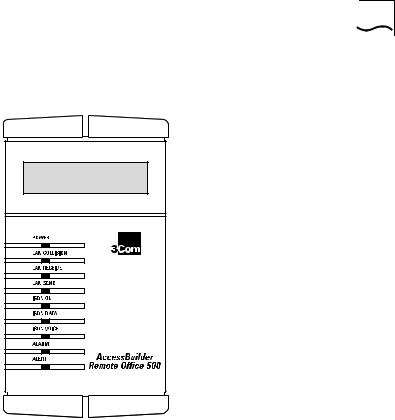
Figure 1-2 AccessBuilder 500 Front Panel Features
POWER This LED indicator shows the following:
■On – Power is connected to the unit and the rear panel On/Off switch is set to the ON position.
■Flash – Indicates that the unit’s main program is corrupted and needs to be reinstalled.
■Off – No power supplied to the unit. See “Troubleshooting” on page 1-48 for more details.

1-10 CHAPTER 1: GETTING STARTED
LAN COLLISION This LED indicator provides a visual indication that a data collision has occurred on the attached LAN. Collisions are a normal part of Ethernet operation. The LED flashes to provide a visual indication of the number of data collisions that are occurring on the LAN:
■Slow flash – Low collision activity.
■Medium flash – Moderate collision activity.
■Quick flash – High collision activity. Continuous high collision activity can indicate that there is too much traffic on your LAN.
LAN RECEIVE This LED indicator provides confirmation that data is being received from the attached LAN. The LED flashes to provide a visual indication of the activity status occurring on the LAN.
■Slow flash – Low LAN activity.
■Medium flash – Moderate LAN activity.
■Quick flash – High LAN activity.
LAN SEND This LED indicator provides confirmation that data is being transmitted to the attached LAN. The LED flashes to provide a visual indication of the activity status occurring on the LAN.
■Slow flash – Low LAN activity.
■Medium flash – Moderate LAN activity.
■Quick flash – High LAN activity.
ISDN OK This LED indicator provides confirmation of the state of the ISDN line.
■On – Indicates the AccessBuilder 500 is connected to a working ISDN line. Sometimes this LED does not light until the first call attempt is made.
■Off – No ISDN connection present.
ISDN DATA This LED indicator provides confirmation that an ISDN call is in progress and that the AccessBuilder 500 is connecting to a remote unit.
Loading...