


 Loading...
GS752TP, GS728TP, and
GS728TPP Gigabit Smart
Switches
Software Administration Manual
350 East Plumeria Drive
San Jose, CA 95134
USA
March 2013 202-11137-02 v1.0

GS752TP, GS728TP, and GS728TPP Gigabit Smart Switches
Support
Thank you for selecting NETGEAR products.
After installing your device, locate the serial number on the label of your product and use it to register your product at https://my.netgear.com. You must register your product before you can use NETGEAR telephone support. NETGEAR recommends registering your product through the NETGEAR website. For product updates and web support, visit http://support.netgear.com.
Phone (US & Canada only): 1-888-NETGEAR.
Phone (Other Countries): Check the list of phone numbers at http://support.netgear.com/general/contact/default.aspx.
Trademarks
NETGEAR, the NETGEAR logo, and Connect with Innovation are trademarks and/or registered trademarks of NETGEAR, Inc. and/or its subsidiaries in the United States and/or other countries. Information is subject to change without notice. © NETGEAR, Inc. All rights reserved.
Revision History
Publication Part Number |
Version |
Publish Date |
Comments |
|
|
|
|
202-11137-02 |
v1.0 |
March 2013 |
Updated document. |
|
|
|
|
202-11137-01 |
v1.0 |
February 2013 |
First publication |
|
|
|
|
2

Contents
Chapter 1 Getting Started
Getting Started with the NETGEAR Switch . . . . . . . . . . . . . . . . . . . . . . . . . 9 Switch Management Interface . . . . . . . . . . . . . . . . . . . . . . . . . . . . . . . . . . 10 Connect the Switch to the Network . . . . . . . . . . . . . . . . . . . . . . . . . . . . . . 11 Discover a Switch in a Network with a DHCP Server . . . . . . . . . . . . . . . . 12 Switch Discovery in a Network Without a DHCP Server . . . . . . . . . . . . . . 14 Configure the Network Settings on the Administrative System . . . . . . . . . 15 Access the Management Interface from the Web . . . . . . . . . . . . . . . . . . . 17
Understand the User Interface. . . . . . . . . . . . . . . . . . . . . . . . . . . . . . . . 17 Use SNMP . . . . . . . . . . . . . . . . . . . . . . . . . . . . . . . . . . . . . . . . . . . . . . . 22 Interface Naming Convention . . . . . . . . . . . . . . . . . . . . . . . . . . . . . . . . . . 24
Chapter 2 Configuring System Information
Management . . . . . . . . . . . . . . . . . . . . . . . . . . . . . . . . . . . . . . . . . . . . . . . 26
System Information . . . . . . . . . . . . . . . . . . . . . . . . . . . . . . . . . . . . . . . . 26
IP Configuration . . . . . . . . . . . . . . . . . . . . . . . . . . . . . . . . . . . . . . . . . . . 27
IPv6 Network Configuration . . . . . . . . . . . . . . . . . . . . . . . . . . . . . . . . . . 29
IPv6 Network Neighbors . . . . . . . . . . . . . . . . . . . . . . . . . . . . . . . . . . . . 31
Time. . . . . . . . . . . . . . . . . . . . . . . . . . . . . . . . . . . . . . . . . . . . . . . . . . . . 32
DNS . . . . . . . . . . . . . . . . . . . . . . . . . . . . . . . . . . . . . . . . . . . . . . . . . . . . 36
Green Ethernet Configuration . . . . . . . . . . . . . . . . . . . . . . . . . . . . . . . . 38
PoE . . . . . . . . . . . . . . . . . . . . . . . . . . . . . . . . . . . . . . . . . . . . . . . . . . . . . . 43
PoE Configuration . . . . . . . . . . . . . . . . . . . . . . . . . . . . . . . . . . . . . . . . . 44
PoE Port Configuration . . . . . . . . . . . . . . . . . . . . . . . . . . . . . . . . . . . . . 45
Timer Global Configuration . . . . . . . . . . . . . . . . . . . . . . . . . . . . . . . . . . 46
Timer Schedule . . . . . . . . . . . . . . . . . . . . . . . . . . . . . . . . . . . . . . . . . . . 47
SNMP . . . . . . . . . . . . . . . . . . . . . . . . . . . . . . . . . . . . . . . . . . . . . . . . . . . . 49
SNMP V1/V2 . . . . . . . . . . . . . . . . . . . . . . . . . . . . . . . . . . . . . . . . . . . . . 49
Trap Flags . . . . . . . . . . . . . . . . . . . . . . . . . . . . . . . . . . . . . . . . . . . . . . . 52
SNMP Supported MIBs . . . . . . . . . . . . . . . . . . . . . . . . . . . . . . . . . . . . . 53
SNMP v3 User Configuration. . . . . . . . . . . . . . . . . . . . . . . . . . . . . . . . . 53
LLDP . . . . . . . . . . . . . . . . . . . . . . . . . . . . . . . . . . . . . . . . . . . . . . . . . . . . . 55
LLDP Configuration . . . . . . . . . . . . . . . . . . . . . . . . . . . . . . . . . . . . . . . . 56
LLDP Port Settings . . . . . . . . . . . . . . . . . . . . . . . . . . . . . . . . . . . . . . . . 57
LLDP-MED Network Policy . . . . . . . . . . . . . . . . . . . . . . . . . . . . . . . . . . 58
LLDP-MED Port Settings . . . . . . . . . . . . . . . . . . . . . . . . . . . . . . . . . . . . 59
Local Information . . . . . . . . . . . . . . . . . . . . . . . . . . . . . . . . . . . . . . . . . . 60
Neighbors Information . . . . . . . . . . . . . . . . . . . . . . . . . . . . . . . . . . . . . . 63
Services—DHCP Snooping. . . . . . . . . . . . . . . . . . . . . . . . . . . . . . . . . . . . 67
Table of Contents | 3

GS752TP, GS728TP, and GS728TPP Gigabit Smart Switches
DHCP Snooping Global Configuration . . . . . . . . . . . . . . . . . . . . . . . . . . 67
DHCP Snooping Interface Configuration . . . . . . . . . . . . . . . . . . . . . . . . 68
DHCP Snooping Binding Configuration . . . . . . . . . . . . . . . . . . . . . . . . . 70
DHCP Snooping Persistent Configuration . . . . . . . . . . . . . . . . . . . . . . . 71
Chapter 3 Configuring Switching Information
Ports . . . . . . . . . . . . . . . . . . . . . . . . . . . . . . . . . . . . . . . . . . . . . . . . . . . . . . 73
Global Configuration. . . . . . . . . . . . . . . . . . . . . . . . . . . . . . . . . . . . . . . . 73
Port Configuration. . . . . . . . . . . . . . . . . . . . . . . . . . . . . . . . . . . . . . . . . . 74
Link Aggregation Groups . . . . . . . . . . . . . . . . . . . . . . . . . . . . . . . . . . . . . . 76
LAG Configuration . . . . . . . . . . . . . . . . . . . . . . . . . . . . . . . . . . . . . . . . . 76
LAG Membership . . . . . . . . . . . . . . . . . . . . . . . . . . . . . . . . . . . . . . . . . . 78
LACP Configuration . . . . . . . . . . . . . . . . . . . . . . . . . . . . . . . . . . . . . . . . 79
LACP Port Configuration . . . . . . . . . . . . . . . . . . . . . . . . . . . . . . . . . . . . 80
VLANs . . . . . . . . . . . . . . . . . . . . . . . . . . . . . . . . . . . . . . . . . . . . . . . . . . . . 81
VLAN Configuration . . . . . . . . . . . . . . . . . . . . . . . . . . . . . . . . . . . . . . . . 81
VLAN Membership Configuration . . . . . . . . . . . . . . . . . . . . . . . . . . . . . . 83
Port VLAN ID Configuration . . . . . . . . . . . . . . . . . . . . . . . . . . . . . . . . . . 84
Voice VLAN . . . . . . . . . . . . . . . . . . . . . . . . . . . . . . . . . . . . . . . . . . . . . . . . 86
Voice VLAN Properties. . . . . . . . . . . . . . . . . . . . . . . . . . . . . . . . . . . . . . 86
Voice VLAN Port Setting . . . . . . . . . . . . . . . . . . . . . . . . . . . . . . . . . . . . 88
Voice VLAN OUI. . . . . . . . . . . . . . . . . . . . . . . . . . . . . . . . . . . . . . . . . . . 88
Auto-VoIP Configuration. . . . . . . . . . . . . . . . . . . . . . . . . . . . . . . . . . . . . . . 90
Spanning Tree Protocol . . . . . . . . . . . . . . . . . . . . . . . . . . . . . . . . . . . . . . . 91
STP Configuration . . . . . . . . . . . . . . . . . . . . . . . . . . . . . . . . . . . . . . . . . 92
CST Configuration . . . . . . . . . . . . . . . . . . . . . . . . . . . . . . . . . . . . . . . . . 94
CST Port Configuration . . . . . . . . . . . . . . . . . . . . . . . . . . . . . . . . . . . . . 96
CST Port Status . . . . . . . . . . . . . . . . . . . . . . . . . . . . . . . . . . . . . . . . . . . 97
Rapid STP . . . . . . . . . . . . . . . . . . . . . . . . . . . . . . . . . . . . . . . . . . . . . . . 98
MST Configuration . . . . . . . . . . . . . . . . . . . . . . . . . . . . . . . . . . . . . . . . . 99
MST Port Configuration . . . . . . . . . . . . . . . . . . . . . . . . . . . . . . . . . . . . 102
Multicast . . . . . . . . . . . . . . . . . . . . . . . . . . . . . . . . . . . . . . . . . . . . . . . . . . 104
MFDB . . . . . . . . . . . . . . . . . . . . . . . . . . . . . . . . . . . . . . . . . . . . . . . . . . 104
Auto-Video Configuration . . . . . . . . . . . . . . . . . . . . . . . . . . . . . . . . . . . 106
IGMP Snooping . . . . . . . . . . . . . . . . . . . . . . . . . . . . . . . . . . . . . . . . . . 107
IGMP Snooping Querier . . . . . . . . . . . . . . . . . . . . . . . . . . . . . . . . . . . . 111
MLD Snooping . . . . . . . . . . . . . . . . . . . . . . . . . . . . . . . . . . . . . . . . . . . 115
Static Multicast Address . . . . . . . . . . . . . . . . . . . . . . . . . . . . . . . . . . . . 119
Forwarding Database . . . . . . . . . . . . . . . . . . . . . . . . . . . . . . . . . . . . . . . . 122
Address Table . . . . . . . . . . . . . . . . . . . . . . . . . . . . . . . . . . . . . . . . . . . 122
Dynamic Address Configuration . . . . . . . . . . . . . . . . . . . . . . . . . . . . . . 124
Chapter 4 Configuring Routing
Configure IP Settings . . . . . . . . . . . . . . . . . . . . . . . . . . . . . . . . . . . . . . . . 126
Configure VLAN Routing . . . . . . . . . . . . . . . . . . . . . . . . . . . . . . . . . . . . . 127
VLAN Routing Wizard. . . . . . . . . . . . . . . . . . . . . . . . . . . . . . . . . . . . . . 127
Configure VLAN Routing . . . . . . . . . . . . . . . . . . . . . . . . . . . . . . . . . . . 129
4

GS752TP, GS728TP, and GS728TPP Gigabit Smart Switches
Configure and View Routes . . . . . . . . . . . . . . . . . . . . . . . . . . . . . . . . . . .130
Configure ARP . . . . . . . . . . . . . . . . . . . . . . . . . . . . . . . . . . . . . . . . . . . . .132
ARP Cache . . . . . . . . . . . . . . . . . . . . . . . . . . . . . . . . . . . . . . . . . . . . . .133
ARP Entry Configuration. . . . . . . . . . . . . . . . . . . . . . . . . . . . . . . . . . . .134
Global ARP Configuration. . . . . . . . . . . . . . . . . . . . . . . . . . . . . . . . . . .135
ARP Entry Management . . . . . . . . . . . . . . . . . . . . . . . . . . . . . . . . . . . .136
Chapter 5 Configure Quality of Service
Class of Service . . . . . . . . . . . . . . . . . . . . . . . . . . . . . . . . . . . . . . . . . . . .138 Basic CoS Configuration. . . . . . . . . . . . . . . . . . . . . . . . . . . . . . . . . . . .138 CoS Interface Configuration . . . . . . . . . . . . . . . . . . . . . . . . . . . . . . . . .140 Queue Configuration. . . . . . . . . . . . . . . . . . . . . . . . . . . . . . . . . . . . . . .141 802.1p to Queue Mapping . . . . . . . . . . . . . . . . . . . . . . . . . . . . . . . . . .142 DSCP to Queue Mapping . . . . . . . . . . . . . . . . . . . . . . . . . . . . . . . . . . .143
Differentiated Services . . . . . . . . . . . . . . . . . . . . . . . . . . . . . . . . . . . . . . .144 Defining DiffServ. . . . . . . . . . . . . . . . . . . . . . . . . . . . . . . . . . . . . . . . . .144 Diffserv Configuration . . . . . . . . . . . . . . . . . . . . . . . . . . . . . . . . . . . . . .145 DSCP Violate Action Mapping . . . . . . . . . . . . . . . . . . . . . . . . . . . . . . .145 Class Configuration . . . . . . . . . . . . . . . . . . . . . . . . . . . . . . . . . . . . . . .147 IPv6 Class Configuration . . . . . . . . . . . . . . . . . . . . . . . . . . . . . . . . . . .149 Policy Configuration . . . . . . . . . . . . . . . . . . . . . . . . . . . . . . . . . . . . . . .152 Service Configuration . . . . . . . . . . . . . . . . . . . . . . . . . . . . . . . . . . . . . .155 Service Statistics . . . . . . . . . . . . . . . . . . . . . . . . . . . . . . . . . . . . . . . . .155
Chapter 6 Managing Device Security
Management Security Settings. . . . . . . . . . . . . . . . . . . . . . . . . . . . . . . . .158
Change Password . . . . . . . . . . . . . . . . . . . . . . . . . . . . . . . . . . . . . . . .158
Configure RADIUS Settings . . . . . . . . . . . . . . . . . . . . . . . . . . . . . . . . .159
Configure TACACS+ . . . . . . . . . . . . . . . . . . . . . . . . . . . . . . . . . . . . . .163
Authentication List Configuration . . . . . . . . . . . . . . . . . . . . . . . . . . . . .165
Configure Management Access . . . . . . . . . . . . . . . . . . . . . . . . . . . . . . . .169
HTTP Configuration . . . . . . . . . . . . . . . . . . . . . . . . . . . . . . . . . . . . . . .169
Secure HTTP Configuration . . . . . . . . . . . . . . . . . . . . . . . . . . . . . . . . .170
Certificate Management . . . . . . . . . . . . . . . . . . . . . . . . . . . . . . . . . . . .171
Access Control . . . . . . . . . . . . . . . . . . . . . . . . . . . . . . . . . . . . . . . . . . .172
Port Authentication . . . . . . . . . . . . . . . . . . . . . . . . . . . . . . . . . . . . . . . . . .175
802.1x Configuration. . . . . . . . . . . . . . . . . . . . . . . . . . . . . . . . . . . . . . .175
Port Authentication . . . . . . . . . . . . . . . . . . . . . . . . . . . . . . . . . . . . . . . .177
Port Summary. . . . . . . . . . . . . . . . . . . . . . . . . . . . . . . . . . . . . . . . . . . .180
Traffic Control . . . . . . . . . . . . . . . . . . . . . . . . . . . . . . . . . . . . . . . . . . . . . .182
Storm Control . . . . . . . . . . . . . . . . . . . . . . . . . . . . . . . . . . . . . . . . . . . .182
Port Security Interface Configuration . . . . . . . . . . . . . . . . . . . . . . . . . .184
Security MAC Address . . . . . . . . . . . . . . . . . . . . . . . . . . . . . . . . . . . . .185
Protected Ports . . . . . . . . . . . . . . . . . . . . . . . . . . . . . . . . . . . . . . . . . . .186
Configure Access Control Lists . . . . . . . . . . . . . . . . . . . . . . . . . . . . . . . .187
ACL Wizard. . . . . . . . . . . . . . . . . . . . . . . . . . . . . . . . . . . . . . . . . . . . . .187
MAC ACL . . . . . . . . . . . . . . . . . . . . . . . . . . . . . . . . . . . . . . . . . . . . . . .190
5

GS752TP, GS728TP, and GS728TPP Gigabit Smart Switches
MAC Rules . . . . . . . . . . . . . . . . . . . . . . . . . . . . . . . . . . . . . . . . . . . . . . 191
MAC Binding Configuration . . . . . . . . . . . . . . . . . . . . . . . . . . . . . . . . . 193
MAC Binding Table. . . . . . . . . . . . . . . . . . . . . . . . . . . . . . . . . . . . . . . . 195
IP ACL . . . . . . . . . . . . . . . . . . . . . . . . . . . . . . . . . . . . . . . . . . . . . . . . . 195
IP Rules . . . . . . . . . . . . . . . . . . . . . . . . . . . . . . . . . . . . . . . . . . . . . . . . 197
IP Extended Rules . . . . . . . . . . . . . . . . . . . . . . . . . . . . . . . . . . . . . . . . 198
IPv6 ACL . . . . . . . . . . . . . . . . . . . . . . . . . . . . . . . . . . . . . . . . . . . . . . . 201
IPv6 Rules . . . . . . . . . . . . . . . . . . . . . . . . . . . . . . . . . . . . . . . . . . . . . . 202
IP Binding Configuration. . . . . . . . . . . . . . . . . . . . . . . . . . . . . . . . . . . . 204
IP Binding Table . . . . . . . . . . . . . . . . . . . . . . . . . . . . . . . . . . . . . . . . . . 206
Chapter 7 Monitoring the System
Ports . . . . . . . . . . . . . . . . . . . . . . . . . . . . . . . . . . . . . . . . . . . . . . . . . . . . . 208
Switch Statistics . . . . . . . . . . . . . . . . . . . . . . . . . . . . . . . . . . . . . . . . . . 208
Port Statistics . . . . . . . . . . . . . . . . . . . . . . . . . . . . . . . . . . . . . . . . . . . . 210
Port Detailed Statistics . . . . . . . . . . . . . . . . . . . . . . . . . . . . . . . . . . . . . 211
EAP Statistics . . . . . . . . . . . . . . . . . . . . . . . . . . . . . . . . . . . . . . . . . . . . 215
Cable Test . . . . . . . . . . . . . . . . . . . . . . . . . . . . . . . . . . . . . . . . . . . . . . 216
Logs . . . . . . . . . . . . . . . . . . . . . . . . . . . . . . . . . . . . . . . . . . . . . . . . . . . . . 218
Buffered Logs . . . . . . . . . . . . . . . . . . . . . . . . . . . . . . . . . . . . . . . . . . . . 218
Server Log . . . . . . . . . . . . . . . . . . . . . . . . . . . . . . . . . . . . . . . . . . . . . . 220
Trap Logs . . . . . . . . . . . . . . . . . . . . . . . . . . . . . . . . . . . . . . . . . . . . . . . 222
Mirroring . . . . . . . . . . . . . . . . . . . . . . . . . . . . . . . . . . . . . . . . . . . . . . . . . . 223
System Resources Utilization. . . . . . . . . . . . . . . . . . . . . . . . . . . . . . . . . . 225
Chapter 8 Maintenance
Reset . . . . . . . . . . . . . . . . . . . . . . . . . . . . . . . . . . . . . . . . . . . . . . . . . . . . 227 Device Reboot . . . . . . . . . . . . . . . . . . . . . . . . . . . . . . . . . . . . . . . . . . . 227 Factory Default . . . . . . . . . . . . . . . . . . . . . . . . . . . . . . . . . . . . . . . . . . . 228 Upload a File from the Switch . . . . . . . . . . . . . . . . . . . . . . . . . . . . . . . . . 229 TFTP File Upload . . . . . . . . . . . . . . . . . . . . . . . . . . . . . . . . . . . . . . . . . 229 HTTP File Upload . . . . . . . . . . . . . . . . . . . . . . . . . . . . . . . . . . . . . . . . . 231 Download a File to the Switch . . . . . . . . . . . . . . . . . . . . . . . . . . . . . . . . . 232 TFTP File Download. . . . . . . . . . . . . . . . . . . . . . . . . . . . . . . . . . . . . . . 232 HTTP File Download . . . . . . . . . . . . . . . . . . . . . . . . . . . . . . . . . . . . . . 234 File Management . . . . . . . . . . . . . . . . . . . . . . . . . . . . . . . . . . . . . . . . . . . 235 Dual Image Configuration. . . . . . . . . . . . . . . . . . . . . . . . . . . . . . . . . . . 235 Dual Image Status . . . . . . . . . . . . . . . . . . . . . . . . . . . . . . . . . . . . . . . . 236 Troubleshooting . . . . . . . . . . . . . . . . . . . . . . . . . . . . . . . . . . . . . . . . . . . . 238 Ping . . . . . . . . . . . . . . . . . . . . . . . . . . . . . . . . . . . . . . . . . . . . . . . . . . . 238 Ping IPv6 . . . . . . . . . . . . . . . . . . . . . . . . . . . . . . . . . . . . . . . . . . . . . . . 239 Traceroute . . . . . . . . . . . . . . . . . . . . . . . . . . . . . . . . . . . . . . . . . . . . . . 240 Remote Diagnostics . . . . . . . . . . . . . . . . . . . . . . . . . . . . . . . . . . . . . . . 242
Chapter 9 Help
Online Help. . . . . . . . . . . . . . . . . . . . . . . . . . . . . . . . . . . . . . . . . . . . . . . . 244
6

GS752TP, GS728TP, and GS728TPP Gigabit Smart Switches
Support . . . . . . . . . . . . . . . . . . . . . . . . . . . . . . . . . . . . . . . . . . . . . . . . .244
User Guide . . . . . . . . . . . . . . . . . . . . . . . . . . . . . . . . . . . . . . . . . . . . . .245
Registration . . . . . . . . . . . . . . . . . . . . . . . . . . . . . . . . . . . . . . . . . . . . . . .246
Appendix A Hardware Specifications and Default Values
Switch Features and Defaults. . . . . . . . . . . . . . . . . . . . . . . . . . . . . . . . . .250
Appendix B Configuration Examples
Virtual Local Area Networks (VLANs). . . . . . . . . . . . . . . . . . . . . . . . . . . .254 Sample VLAN Configuration. . . . . . . . . . . . . . . . . . . . . . . . . . . . . . . . .255 Access Control Lists (ACLs). . . . . . . . . . . . . . . . . . . . . . . . . . . . . . . . . . .256 Sample MAC ACL Configuration . . . . . . . . . . . . . . . . . . . . . . . . . . . . .256 Sample Standard IP ACL Configuration . . . . . . . . . . . . . . . . . . . . . . . .257 Differentiated Services (DiffServ) . . . . . . . . . . . . . . . . . . . . . . . . . . . . . . .259 Class. . . . . . . . . . . . . . . . . . . . . . . . . . . . . . . . . . . . . . . . . . . . . . . . . . .259 DiffServ Traffic Classes . . . . . . . . . . . . . . . . . . . . . . . . . . . . . . . . . . . .260 Create Policies . . . . . . . . . . . . . . . . . . . . . . . . . . . . . . . . . . . . . . . . . . .260 Sample DiffServ Configuration . . . . . . . . . . . . . . . . . . . . . . . . . . . . . . .261 802.1x. . . . . . . . . . . . . . . . . . . . . . . . . . . . . . . . . . . . . . . . . . . . . . . . . . . .263 Sample 802.1x Configuration . . . . . . . . . . . . . . . . . . . . . . . . . . . . . . . .264 MSTP . . . . . . . . . . . . . . . . . . . . . . . . . . . . . . . . . . . . . . . . . . . . . . . . . . . .266 Sample MSTP Configuration . . . . . . . . . . . . . . . . . . . . . . . . . . . . . . . .267 Configure VLAN Routing with Static Route . . . . . . . . . . . . . . . . . . . . . . .270 VLAN Routing Overview . . . . . . . . . . . . . . . . . . . . . . . . . . . . . . . . . . . .270 Sample VLAN Routing Configuration . . . . . . . . . . . . . . . . . . . . . . . . . .270
Chapter 10 Notification of Compliance
Index
7

1. Getting Started |
1 |
|
|
||
|
|
|
This manual describes how to configure and operate the GS752TP, GS728TP, and GS728TPP Gigabit Smart Switches by using the web-based graphical user interface (GUI). This manual describes the software configuration procedures and explains the options available within those procedures. These switches are referred to as the NETGEAR switch throughout this document.
8

GS752TP, GS728TP, and GS728TPP Gigabit Smart Switches
Getting Started with the NETGEAR Switch
This chapter provides an overview of starting your NETGEAR switch and accessing the user interface. It also describes some actions that can be performed in the Smart Control Center (SCC) application, which can be downloaded to your computer.
This guide does not document the SCC application. Full documentation for SCC is found at http://docs.netgear.com/scc/enu/202-10685-01/index.htm.
This chapter contains the following sections:
•Switch Management Interface
•Connect the Switch to the Network
•Discover a Switch in a Network with a DHCP Server
•Switch Discovery in a Network Without a DHCP Server
•Configure the Network Settings on the Administrative System
•Access the Management Interface from the Web
•Interface Naming Convention
9

GS752TP, GS728TP, and GS728TPP Gigabit Smart Switches
Switch Management Interface
The NETGEAR switch contains an embedded web server and management software for managing and monitoring switch functions. The switch functions as a simple switch without the management software. However, you can use the management software to configure more advanced features that can improve switch efficiency and overall network performance.
Web-based management lets you monitor, configure, and control your switch remotely using a standard web browser instead of using expensive and complicated SNMP software products. From your web browser, you can monitor the performance of your switch and optimize its configuration for your network. You can configure all switch features, such as VLANs, QoS, and ACLs, by using the web-based management interface.
NETGEAR provides the Smart Control Center utility with this product. This program runs under Windows XP, Windows 2003, Windows 2008 or Windows 7 (32 bit and 64 bit) and provides a front end that discovers the switches on your network segment (L2 broadcast domain). When you power up your switch for the first time, use the Smart Control Center to discover the switch and view the network information that was automatically assigned to the switch by a DHCP server; or, if no DHCP server is present on the network, use the Smart Control Center to discover the switch and assign static network information.
10
GS752TP, GS728TP, and GS728TPP Gigabit Smart Switches
Connect the Switch to the Network
To enable remote management of the switch through a web browser or SNMP, you must connect the switch to the network and configure it with network information (an IP address, subnet mask, and default gateway). The switch has a default IP address of 192.168.1.1 and a default subnet mask of 255.255.255.0.
To change the default network information about the switch, use one of the following three methods:
•Dynamic assignment through DHCP. DHCP is enabled by default on the switch. If you connect the switch to a network with a DHCP server, the switch obtains its network information automatically. You can use the Smart Control Center to discover the automatically assigned network information. For more information, see Switch Discovery in a Network Without a DHCP Server on page 14.
•Static assignment through the Smart Control Center. If you connect the switch to a network that does not have a DHCP server, you can use the Smart Control Center to assign a static IP address, subnet mask, and default gateway. For more information, see
Switch Discovery in a Network Without a DHCP Server on page 14.
•Static assignment by connecting from a local host. If you do not want to use the Smart Control Center to assign a static address, you can connect to the switch from a host (administrative system) in the 192.168.0.0/24 network and change the settings by using the web-based management interface on the switch. For information about how to set the IP address on the administrative system so it is in the same subnet as the default IP address of the switch, see Configure the Network Settings on the Administrative System on page 15.
11
GS752TP, GS728TP, and GS728TPP Gigabit Smart Switches
Discover a Switch in a Network with a DHCP Server
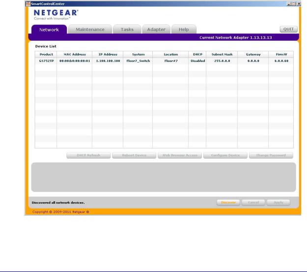
This section describes how to set up your switch in a network that has a DHCP server. The DHCP client on the switch is enabled by default. When you connect it to your network, the DHCP server automatically assigns an IP address to your switch. To discover the IP address automatically assigned to the switch, use the Smart Control Center.
To install the switch in a network with a DHCP server, use the following steps:
1.Connect the switch to a network with a DHCP server.
2.Power on the switch by connecting its power cord.
3.Install the Smart Control Center on your computer.
4.Start the Smart Control Center.
5.Click Discover for the Smart Control Center to find your switch. A screen similar to the one shown below is displayed.
6.Make a note of the displayed IP address assigned by the DHCP server.
You need this value to access the switch directly from a web browser (without using the Smart Control Center).
12
GS752TP, GS728TP, and GS728TPP Gigabit Smart Switches
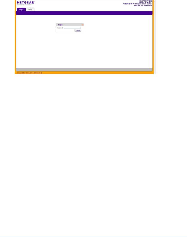
7.Select your switch by clicking the line that displays the switch, then click the
Web Browser Access button.
The Smart Control Center displays a login window.
To manage your switch, use your web browser. The default password is password. Use this screen to manage your switch. For more information, see Access the Management Interface from the Web on page 17.
13

GS752TP, GS728TP, and GS728TPP Gigabit Smart Switches
Switch Discovery in a Network Without a DHCP Server
This section describes how to use the Smart Control Center to set up your switch in a network without a DHCP server. If your network has no DHCP service, you must assign a static IP address to your switch. You can assign it a static IP address, even if your network has DHCP service.
To assign a static IP address:
1.Connect the switch to your existing network.
2.Power on the switch by connecting its power cord.
3.Install the Smart Control Center on your computer.
4.Start the Smart Control Center.
5.Click Discover for the Smart Control Center to find your NETGEAR switch.
The utility broadcasts Layer 2 discovery packets within the broadcast domain to discover the switch.
6.Select the switch, then click Configure Device.
The screen expands to display more fields at the bottom of the screen.
.
14

GS752TP, GS728TP, and GS728TPP Gigabit Smart Switches
7.Select the Disabled radio button to disable DHCP.
8.Enter the static switch IP address, gateway IP address, and subnet mask for the switch and type your password.
Tip: You must enter the current password every time you use the Smart Control Center to update the switch setting. The default password is password.
9. Click APPLY to configure the switch with the network settings.
Ensure that your computer and the switch are in the same subnet. Make a note of these settings for later use.
Configure the Network Settings on the Administrative System
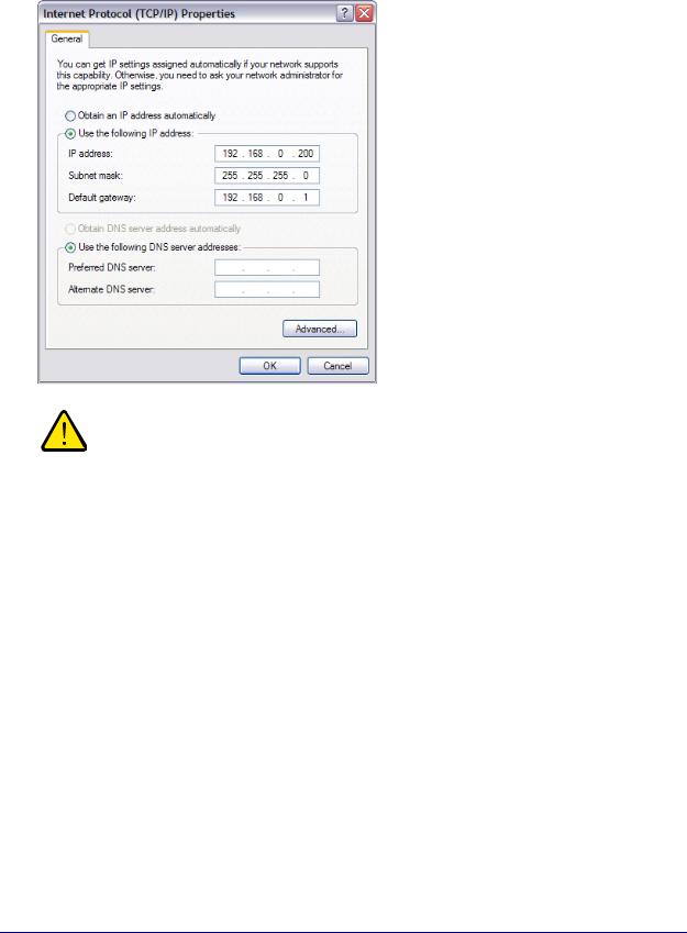
If you do not use the Smart Control Center to configure the switch network information, you can connect directly to the switch from the administrative system installed on your computer. The IP address of the administrative system must be in the same subnet as the default IP address on the switch. For most networks, this means you must change the IP address of the administrative system to be on the same subnet as the default IP address of the switch (192.168.1.1).
To change the IP address on an administrative system running a Windows operating system, open the Internet Protocol (TCP/IP) Properties screen that you access from each local area connection, as shown in the following screen. You need Windows Administrator privileges to change these settings.
15
GS752TP, GS728TP, and GS728TPP Gigabit Smart Switches
WARNING:
When you change the IP address of your administrative system, connection to the rest of the network is lost. Be sure to write down your current network address settings before you change them.
To modify the network settings on your administrative system:
1.On your computer, access the Windows operating system TCP/IP Properties screen.
2.Set the IP address of the administrative system to an address in the 192.168.0.0 network, such as 192.168.0.200.
The IP address must be different from the switch’s address but within the same subnet.
3.Click OK.
To configure a static address on the switch:
1.Use a straight-through cable to connect the Ethernet port on the administrative system directly to any port on the NETGEAR switch.
2.Open a web browser on your computer and connect to the management interface.
For more information, see Access the Management Interface from the Web on page 17.
3.Change the network settings on the switch to match the settings on your network. For more information, see IP Configuration on page 27.
4.Return the network configuration on your administrative system to the original settings.
16

GS752TP, GS728TP, and GS728TPP Gigabit Smart Switches
Access the Management Interface from the Web
To access the switch management interface, use one of the following methods:
•From the Smart Control Center, select the switch and click Web Browser Access. For more information, see the documentation for this application at http://docs.netgear.com/scc/enu/202-10685-01/index.htm.
•Open a web browser and enter the IP address of the switch in the address field.
You must be able to ping the IP address of the NETGEAR switch management interface from your administrative system for web access to be available. If you used the Smart Control Center to set up the IP address and subnet mask, either with or without a DHCP server, use that IP address in the address field of your web browser. If you did not change the IP address of the switch from the default value, enter 192.168.0.239 into the address field.
Clicking Web Browser Access on the Smart Control Center or accessing the switch directly from your web browser displays the Login screen.
Understand the User Interface
To access the switch by using a web browser, the browser must meet the following software requirements:
•Internet Explorer version 7 or later
•Firefox version 4 or later
To log on to the web interface:
1. Open a web browser and enter the IP address of the switch in the web browser address field.
2. The factory default password is password. Type the password in the field on the Login screen and click Login. Passwords are case-sensitive.
17

GS752TP, GS728TP, and GS728TPP Gigabit Smart Switches
3. After the system authenticates you, the System Information screen displays.
Navigation tab |
Configuration menus |
Help link |
Logout button |
Help screen
Configuration status and options
Screen menu
Figure 1. Configuration Status and Options
Navigation Tabs, Configuration Menus, and Screen Menu
The navigation tabs along the top of the web interface give you quick access to the various switch functions. The tabs are always available and remain constant, regardless of which feature you configure.
When you select a tab, the features for that tab appear as menus directly under the tabs. The menus in the blue bar change according to the navigation tab that is selected.
The configuration screens for each feature are available as submenu links in the screen menu on the left side of the screen.
18

GS752TP, GS728TP, and GS728TPP Gigabit Smart Switches
Some items in the menu expand to reveal multiple submenu links, as shown in the following:
Link
Submenu
Links
When you click a menu item that includes multiple configuration screens, the item becomes preceded by a down arrow symbol and expands to display the additional submenu links.
Configuration and Status Options
The area directly below the feature links and to the right of the links displays the configuration information or status for the screen you select. On screens that contain configuration options, you can enter information into fields or select options from drop-down lists.
Each screen contains access to the HTML-based help that explains the fields and configuration options for the screen. Each screen also contains command buttons.
The following table shows the command buttons that are used throughout the screens in the web interface.
Table 1. Command Buttons
Button |
Function |
|
|
ADD |
Places the new item configured in the heading row of a table. |
|
|
APPLY |
Sends the updated configuration to the switch. Configuration changes take effect |
|
immediately. |
|
|
CANCEL |
Resets the data on the screen to the latest value of the switch. |
|
|
DELETE |
Removes the selected item. |
|
|
REFRESH |
Reloads the screen with the latest information from the device. |
|
|
LOGOUT |
Ends the session. |
|
|
Device View
The Device View is a Java applet that displays the ports on the switch. This graphic provides an alternate way to navigate to configuration and monitoring options. The graphic also provides information about device ports, current configuration and status, table information, and feature components.
19

GS752TP, GS728TP, and GS728TPP Gigabit Smart Switches
The Device View is available by selecting System Device View.
Depending upon the status of the port, the LED of the port status lights. Green indicates that the port is enabled. Red indicates that an error occurred on the port and the link is disabled. The LED of the port speed light in either green or yellow.
•A green LED indicates operational ports at the link speed of 1000 Mbps.
•A yellow LED indicates operational ports at the link speed of 10/100 Mbps.
The system LEDs are on the left side of the front panel.
Power/Status LED
The Power LED is a bicolor LED that serves as an indicator of power and diagnostic status. The following indications are given by the following LED states:
•A solid green LED indicates that the power is supplied to the switch from the internal power supply and is operating normally.
•A blinking green LED indicates that the internal power supply has failed, and that the system is drawing power from a remote power supply or PoE power from an external power supply.
•A solid yellow LED indicates that system is in the boot-up stage.
•No lit LED indicates that power is disconnected.
FAN Status LED
FAN status is indicated as follows:
•A solid yellow LED indicates that the fan is faulty.
•No lit LED indicates that the fan is operating normally.
Max PoE LED
The Max PoE LED indicates the following:
•A solid yellow LED indicates that less than seven watts of PoE power are available.
•A blinking yellow LED indicates that the PoE Max LED was lit within the previous 2 minutes.
•No lit LED indicates that at least seven watts of PoE power are available.
LED Status LED
The LED Status LED indicates the following:
•A solid green LED indicates that the Port LED is in Ethernet Mode.
•A solid yellow LED indicates that the Port LED is in PoE Mode.
20

GS752TP, GS728TP, and GS728TPP Gigabit Smart Switches
The following image shows the device view of the NETGEAR switch.
Figure 2. Ports and LEDs on the Switching Devices
Click the port you want to view or configure to see a menu that displays statistics and configuration options. Click the menu option to access the screen that contains the configuration or monitoring options.
Figure 3. Device View
21
GS752TP, GS728TP, and GS728TPP Gigabit Smart Switches
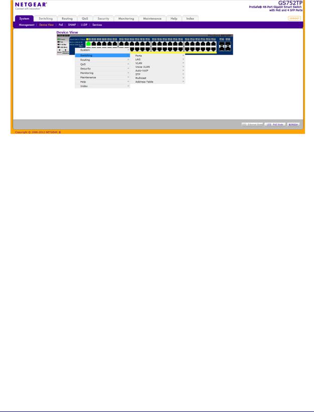
If you right-click the graphic, the main menu displays.
Figure 4. Device View Drop Down Menus
Help Screen Access
Every screen contains a link to the online help  , which contains information to help configure and manage the switch. The online help screens are context-sensitive. For example, if the IP Addressing screen is open, the help topic for that screen displays if you click Help. Figure 1, Configuration Status and Options shows the location of the Help link on the web interface.
User-Defined Fields
User-defined fields can contain 1 to 159 characters, unless otherwise noted on the configuration web screen. All characters can be used except for the following (unless specifically noted in for that feature):
\ |
< |
/ |
>| |
* |
| |
? |
|
Use SNMP
The switch software supports the configuration of SNMP groups and users that can manage traps that the SNMP agent generates.
The switch uses both standard public MIBs for standard functionality and private MIBs that support more switch functionality. All private MIBs begin with a hyphen (-) prefix. The main
22

GS752TP, GS728TP, and GS728TPP Gigabit Smart Switches
object for interface configuration is in -SWITCHING-MIB, which is a private MIB. Some interface configurations also involve objects in the public MIB, IF-MIB.
SNMP is enabled by default. The System Information web screen, which displays after a successful login, displays the information you need to configure an SNMP manager to access the switch.
Any user can connect to the switch using the SNMPv3 protocol. However, for authentication and encryption, the switch only supports a single user called admin, which is the only profile that can be created or modified.
To configure authentication and encryption settings for the SNMPv3 admin profile by using the web interface:
1.Select the System SNMP SNMPv3 User Configuration screen.
2.To enable authentication, select one of MD5 and SHA authentication protocol options.
3.To enable encryption:
a.Select DES as the encryption protocol.
b.In the Encryption Key field, enter an encryption code of eight or more alphanumeric characters.
4.Click APPLY.
To access configuration information for SNMPv1 or SNMPv2:
1.Select System SNMP SNMPv1/v2
2.Follow the link to the screen that contains the information to configure.
23

GS752TP, GS728TP, and GS728TPP Gigabit Smart Switches
Interface Naming Convention
The switch supports physical and logical interfaces. Interfaces are identified by their type and the interface number. The switches support the following ports:
•GS752TP. Ports 1–48 are 10/100/1000M AutoSensing Gigabit ports, and ports 49–52 are 100/1000M SFP ports. The first 8 ports are PoE+ providing 30W of DC power, and the remaining copper ports are PoE (Power over Environment) providing 15.4W of DC power.
•GS728TP. Ports 1–24 are 10/100/1000M AutoSensing Gigabit ports, and ports 25–28 are 100/1000M SFP ports. The first 8 ports are PoE+ providing 30W of DC power, and the remaining copper ports are PoE (Power over Environment) providing 15.4W of DC power.
•GS728TPP. Ports 1–24 are 10/100/1000M AutoSensing Gigabit ports, and ports 25–28 are 100/1000M SFP ports. All 24 copper ports are PoE+ providing 30W of DC power. This model includes an external power supply to support the increased power requirements.
The number of the port is identified on the front panel. You can configure the logical interfaces by using the software. The following table describes the naming convention for all interfaces available on the switch.
Table 2. Naming Convention for Switch Interfaces
Interface |
Description |
Example |
|
|
|
Physical |
The physical ports include Gigabit ports and are numbered |
g1, g2, g3 |
|
sequentially starting from 1. |
|
|
|
|
Link aggregation group (LAG) |
LAG interfaces are logical interfaces that are used only for |
l1, l2, l3 |
|
bridging functions. |
|
|
|
|
CPU Management Interface |
This is the internal switch interface responsible for the |
c1 |
|
switch base MAC address. This interface is not |
|
|
configurable and is always listed in the MAC Address |
|
|
Table. |
|
|
|
|
24

2. Configuring System Information |
2 |
|
|
||
|
|
|
Use the features in the System tab to define the switch’s relationship to its environment. The System tab contains links to screens described in the following sections:
•Management
•PoE
•SNMP
•LLDP
•Services—DHCP Snooping
25
GS752TP, GS728TP, and GS728TPP Gigabit Smart Switches
Management
This section describes how to display the switch status and specify some basic switch information, such as the management interface IP address, system clock settings, and DNS information. From the Management menu, you can access screens described in the following sections:
•System Information
•IP Configuration
•IPv6 Network Configuration
•IPv6 Network Neighbors
•Time
•DNS
•Green Ethernet Configuration
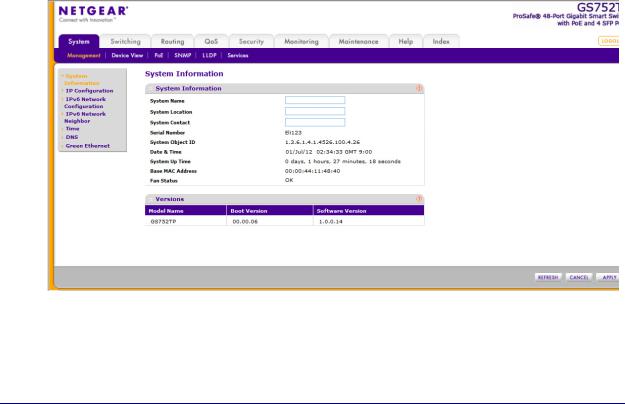
System Information
After a successful login, the System Information screen displays. Use this screen to configure and view general device information.
To define system information:
1.Select System Management System Information. The following screen displays:
2.Define the following fields:
•System Name. Enter the name you want to use to identify this switch. You can use up to 160 alphanumeric characters. The factory default is blank.
26

GS752TP, GS728TP, and GS728TPP Gigabit Smart Switches
•System Location. Enter the location of this switch. You can use up to 160 alphanumeric characters. The factory default is blank.
•System Contact. Enter the contact person for this switch. You can use up to 160 alphanumeric characters. The factory default is blank.
3.Click APPLY to apply the changes to the system.
Table 3 describes the status information displayed in the System screen.
Table 3. System status information
Field |
Description |
Serial Number |
The serial number of the switch. |
|
|
System Object ID |
The base object ID for the switch's enterprise MIB. |
|
|
Date & Time |
The current date and time. |
|
|
System Up Time |
Displays the number of days, hours, and minutes since the last system |
|
restart. |
Base MAC Address |
Universally assigned network address. |
|
|
Fan Status |
The status of fan operation. |
|
|
Model Name |
The model name of the switch. |
|
|
Boot Version |
The boot code version of the switch. |
|
|
Software Version |
The software version of the switch. |
|
|
IP Configuration
Use the IP Configuration screen to configure network information for the management interface, which is the logical interface used for in-band connectivity with the switch through any of the switch's front-panel ports. The configuration parameters associated with the switch's network interface do not affect the configuration of the front panel ports through which traffic is switched or routed.
27
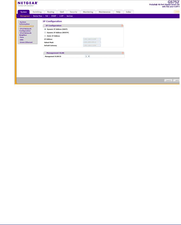
GS752TP, GS728TP, and GS728TPP Gigabit Smart Switches
To configure the network information for the management interface:
1.Select System Management IP Configuration. The following screen displays:
2.Select the appropriate radio button to determine how to configure the network information for the switch management interface:
•Dynamic IP Address (DHCP). Specifies that the switch must obtain the IP address through a DHCP server.
•Dynamic IP Address (BOOTP). Specifies that the switch must obtain the IP address through a BootP server.
•Static IP Address. Specifies that the IP address, subnet mask, and default gateway must be manually configured. Enter this information in the fields below this radio button.
3.If you selected the Static IP Address option, configure the following network information:
•IP Address. The IP address of the network interface. The factory default value is 192.168.0.239. Each part of the IP address must start with a number other than 0. For example, IP addresses 001.100.192.6 and 192.001.10.3 are not valid.
•Subnet Mask. The IP subnet mask for the interface. The factory default value is 255.255.255.0.
•Default Gateway. The default gateway for the IP interface.
4.Specify the VLAN ID for the management VLAN.
The management VLAN is used to establish an IP connection to the switch from a workstation that is connected to a port in the same VLAN. If not specified, the active management VLAN ID is 1 (default), which allows an IP connection to be established through any port.
28

GS752TP, GS728TP, and GS728TPP Gigabit Smart Switches
When the management VLAN is set to a different value, an IP connection can be made only through a port that is part of the management VLAN. It is also mandatory that the port VLAN ID (PVID) of the port to be connected in that management VLAN be the same as the management VLAN ID.
Note: Make sure that the PVID of at least one port that is a port of the VLAN is the same as the management VLAN ID. For information about creating VLANs and configuring the PVID for a port, see
VLANs .
The management VLAN has the following requirements:
•Only one management VLAN can be active at a time.
•When a new management VLAN is configured, connectivity through the existing management VLAN is lost.
•The management station must be reconnected to the port in the new management VLAN.
5.Click APPLY to apply the changes to the system.
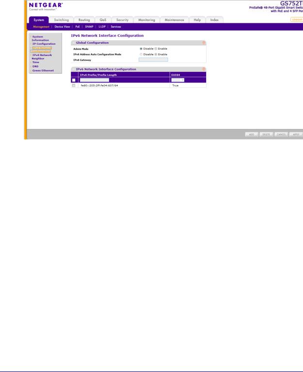
IPv6 Network Configuration
Use the IPv6 Network Configuration screen to configure the IPv6 network interface, which is the logical interface used for in-band connectivity with the switch through all of the switch's front-panel ports. The configuration parameters associated with the switch's network interface do not affect the configuration of the front-panel ports through which traffic is switched or routed.
To access the switch over a IPv6 network, you must initially configure the switch with IPv6 information (IPv6 prefix, prefix length, and default gateway). IPv6 can be configured using IPv6 autoconfiguration.
When in-band connectivity is established, IPv6 information can be changed using any of the following:
•SNMP-based management
•Web-based management
29
GS752TP, GS728TP, and GS728TPP Gigabit Smart Switches
To configure the global settings for an IPv6 Interface:
1.Select System Management IPv6 Network Configuration. The following screen displays:
2.In the Global Configuration Section, configure the following:
•Admin Mode. Enable or disable the IPv6 network interface on the switch. The default value is Enable.
•IPv6 Address Auto Configuration Mode. The IPv6 address for the IPv6 network interface is automatically configured if this option is enabled. The default value is Disable.
•IPv6 Gateway. Specify the gateway for the IPv6 network interface. The gateway address is in IPv6 global or link-local address format.
3.Click APPLY to apply the changes to the system.
To modify IPv6 addresses on the network interface:
1.Select System Management IPv6 Network Configuration.
2.in the IPv6 Network Interface Configuration section, configure the following:
•IPv6 Prefix/Prefix Length. Select an existing IPv6 prefix and prefix length from the list, or add a new IPv6 prefix and prefix length to the list of IPv6 addresses. The address is in the global address format.
•EUI64. Specify whether the IPv6 address is in EUI-64 format. The default value is False.
3.Click ADD to add a new IPv6 address, or click DELETE to delete a selected IPv6 address from the list of IPv6 addresses.
4.Click APPLY to apply the changes to the system.
30
Loading...