


 Loading...
Dell K802N, H928N, J718N, K811N, 1000W User Manual
...Dellt Line-Interactive Rack UPS 1000W, 1920/1500W, and 2700/2300W
User's Guide
H919N, J718N, K792N, H928N, K802N, H945N, J727N
J735N, K811N
w w w . d e l l . c o m | s u p p o r t . d e l l . c o m

Notes and Warnings
NOTE: A NOTE indicates important information that helps you make better use of your software.
DANGER: A DANGER indicates an imminently hazardous situation which, if not avoided, will result in death or serious injury.
WARNING: A WARNING indicates a potentially hazardous situation which, if not avoided, could result in death or injury.
CAUTION: A CAUTION indicates a potentially hazardous situation which, if not avoided, may result in minor or moderate injury or in property damage incidents.
DANGER: Observe the following instruction to help prevent an imminently hazardous situation which, if not avoided, will result in death or serious injury:
SThis UPS contains LETHAL VOLTAGES. All repairs and service should be performed by
AUTHORIZED SERVICE PERSONNEL ONLY. There are NO USER SERVICEABLE PARTS inside the UPS.
Information in this document is subject to change without notice.
E 2009 Dell Inc. All rights reserved.
Reproduction in any manner whatsoever without the written permission of Dell Inc. is strictly forbidden.
Trademarks used in this text: Dell and the DELL logo are trademarks of Dell Inc.; National Electrical Code and NEC are registered trademarks of National Fire Protection Association, Inc.; Phillips is a registered trademark of Phillips Screw Company.
Other trademarks and trade names may be used in this document to refer to either the entities claiming the marks and names or their products. Dell Inc. disclaims any proprietary interest in trademarks and trade names other than its own.
September 2009 S 164201787 4
Table of Contents
1 |
Introduction |
|
|
Finding Information . . . . . . . . . . . . . . . . . . . . . . . . . . . . . . . . . . . . . . . . . . . . . . . |
8 |
2 |
Safety Warnings |
|
3 |
Installation |
|
|
Inspecting the Equipment . . . . . . . . . . . . . . . . . . . . . . . . . . . . . . . . . . . . . . . . . . |
12 |
|
Unpacking the Cabinet . . . . . . . . . . . . . . . . . . . . . . . . . . . . . . . . . . . . . . . . . . . . |
13 |
|
Identifying the UPS Rear Panels . . . . . . . . . . . . . . . . . . . . . . . . . . . . . . . . . . . . . |
15 |
|
Identifying the UPS Front Panel . . . . . . . . . . . . . . . . . . . . . . . . . . . . . . . . . . . . . |
18 |
|
UPS Setup . . . . . . . . . . . . . . . . . . . . . . . . . . . . . . . . . . . . . . . . . . . . . . . . . . . . . . |
19 |
|
Rackmount Setup . . . . . . . . . . . . . . . . . . . . . . . . . . . . . . . . . . . . . . . . . . . . . |
19 |
|
Tower Setup . . . . . . . . . . . . . . . . . . . . . . . . . . . . . . . . . . . . . . . . . . . . . . . . . |
24 |
|
Installing the EBM . . . . . . . . . . . . . . . . . . . . . . . . . . . . . . . . . . . . . . . . . . . . . . . |
28 |
|
Installing the UPS . . . . . . . . . . . . . . . . . . . . . . . . . . . . . . . . . . . . . . . . . . . . . . . . |
30 |
|
Installing Remote Emergency Power-off . . . . . . . . . . . . . . . . . . . . . . . . . . . . . . |
30 |
|
UPS Initial Startup . . . . . . . . . . . . . . . . . . . . . . . . . . . . . . . . . . . . . . . . . . . . . . . |
32 |
4 |
Operation |
|
|
UPS Startup and Shutdown . . . . . . . . . . . . . . . . . . . . . . . . . . . . . . . . . . . . . . . . . |
37 |
|
Starting the UPS . . . . . . . . . . . . . . . . . . . . . . . . . . . . . . . . . . . . . . . . . . . . . . |
37 |
|
Starting the UPS on Battery . . . . . . . . . . . . . . . . . . . . . . . . . . . . . . . . . . . . . |
38 |
|
UPS Shutdown . . . . . . . . . . . . . . . . . . . . . . . . . . . . . . . . . . . . . . . . . . . . . . . |
38 |
|
Control Panel Functions . . . . . . . . . . . . . . . . . . . . . . . . . . . . . . . . . . . . . . . . . . . |
39 |
|
Changing the Language . . . . . . . . . . . . . . . . . . . . . . . . . . . . . . . . . . . . . . . . . . . |
40 |
Table of Contents |
| |
3 |
Display Functions . . . . . . . . . . . . . . . . . . . . . . . . . . . . . . . . . . . . . . . . . . . . . . . . |
40 |
Startup Screen . . . . . . . . . . . . . . . . . . . . . . . . . . . . . . . . . . . . . . . . . . . . . . . |
40 |
Screen Locked . . . . . . . . . . . . . . . . . . . . . . . . . . . . . . . . . . . . . . . . . . . . . . . |
41 |
UPS Status . . . . . . . . . . . . . . . . . . . . . . . . . . . . . . . . . . . . . . . . . . . . . . . . . . |
41 |
Event Log . . . . . . . . . . . . . . . . . . . . . . . . . . . . . . . . . . . . . . . . . . . . . . . . . . . |
44 |
Measurements . . . . . . . . . . . . . . . . . . . . . . . . . . . . . . . . . . . . . . . . . . . . . . . |
44 |
Control Screens . . . . . . . . . . . . . . . . . . . . . . . . . . . . . . . . . . . . . . . . . . . . . . |
45 |
Identification . . . . . . . . . . . . . . . . . . . . . . . . . . . . . . . . . . . . . . . . . . . . . . . . . |
46 |
Settings . . . . . . . . . . . . . . . . . . . . . . . . . . . . . . . . . . . . . . . . . . . . . . . . . . . . . |
46 |
Retrieving the Event Log . . . . . . . . . . . . . . . . . . . . . . . . . . . . . . . . . . . . . . . . . . . |
50 |
Behavior on Overload . . . . . . . . . . . . . . . . . . . . . . . . . . . . . . . . . . . . . . . . . . . . . |
50 |
Configuring Load Segments . . . . . . . . . . . . . . . . . . . . . . . . . . . . . . . . . . . . . . . . |
51 |
Controlling Load Segments Through the Display . . . . . . . . . . . . . . . . . . . . . |
51 |
Configuring Automatic Start Delay . . . . . . . . . . . . . . . . . . . . . . . . . . . . . . . . |
52 |
Configuring Automatic on Battery Shutdown . . . . . . . . . . . . . . . . . . . . . . . . |
53 |
Configuring Battery Settings . . . . . . . . . . . . . . . . . . . . . . . . . . . . . . . . . . . . . . . . |
54 |
Configuring the UPS for an EBM . . . . . . . . . . . . . . . . . . . . . . . . . . . . . . . . . . |
54 |
Running Automatic Battery Tests . . . . . . . . . . . . . . . . . . . . . . . . . . . . . . . . . |
55 |
Configuring Automatic Battery Tests . . . . . . . . . . . . . . . . . . . . . . . . . . . . . . |
55 |
Configuring Automatic Restart . . . . . . . . . . . . . . . . . . . . . . . . . . . . . . . . . . . . . . |
55 |
5 Additional UPS Features
RS-232 and USB Communication Ports . . . . . . . . . . . . . . . . . . . . . . . . . . . . . . . . 56
Dell Network Management Card (Optional) . . . . . . . . . . . . . . . . . . . . . . . . . 58
Dell UPS Management Software . . . . . . . . . . . . . . . . . . . . . . . . . . . . . . . . . . . . |
59 |
4 |
| |
Table of Contents |
6 |
UPS Maintenance |
|
|
UPS and Battery Care . . . . . . . . . . . . . . . . . . . . . . . . . . . . . . . . . . . . . . . . . . . . . |
60 |
|
Transporting the UPS . . . . . . . . . . . . . . . . . . . . . . . . . . . . . . . . . . . . . . . . . . . . . |
61 |
|
Storing the UPS and Batteries . . . . . . . . . . . . . . . . . . . . . . . . . . . . . . . . . . . . . . |
63 |
|
When to Replace Batteries . . . . . . . . . . . . . . . . . . . . . . . . . . . . . . . . . . . . . . . . . |
64 |
|
Testing Batteries . . . . . . . . . . . . . . . . . . . . . . . . . . . . . . . . . . . . . . . . . . . . . . . . |
64 |
|
Updating the UPS Firmware . . . . . . . . . . . . . . . . . . . . . . . . . . . . . . . . . . . . . . . . |
64 |
7 |
Specifications |
|
8 |
Troubleshooting |
|
|
Accessing Alarms and Conditions . . . . . . . . . . . . . . . . . . . . . . . . . . . . . . . . . . . |
69 |
|
UPS Status Menu . . . . . . . . . . . . . . . . . . . . . . . . . . . . . . . . . . . . . . . . . . . . . |
69 |
|
Event Log Menu . . . . . . . . . . . . . . . . . . . . . . . . . . . . . . . . . . . . . . . . . . . . . . |
70 |
|
Typical Alarms and Conditions . . . . . . . . . . . . . . . . . . . . . . . . . . . . . . . . . . . . . . |
70 |
|
Silencing the Alarm . . . . . . . . . . . . . . . . . . . . . . . . . . . . . . . . . . . . . . . . . . . . . . |
73 |
Table of Contents |
| |
5 |
1
Introduction
The Dellt Line-Interactive Rack uninterruptible power system (UPS) protects your sensitive electronic equipment from basic power problems such as power failures, power sags, power surges, brownouts, and line noise.
Power outages can occur when you least expect them and power quality can be erratic. These power problems have the potential to corrupt critical data, destroy unsaved work sessions, and damage hardware — causing hours of lost productivity and expensive repairs.
With the Dell Line-Interactive Rack UPS, you can safely eliminate the effects of power disturbances and guard the integrity of your equipment. The UPS's flexibility to handle an array of network devices makes it the perfect choice to protect your LANs, servers, workstations, and other electrical equipment.
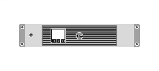
Figure 1 shows the Dell Line-Interactive Rack UPS.
Figure 1. The Dell Line-Interactive Rack UPS
6 | Introduction
Providing outstanding performance and reliability, the UPS's unique benefits include:
SBuck and Boost voltage regulation that ensures regulated voltage to your load by correcting voltage fluctuations.
SStart on battery capability for powering up the UPS even if utility power is not available.
SMaintenance is simplified by allowing the safe replacement of batteries without powering down the UPS.
SExtended runtime with an optional External Battery Module (EBM) for 1500–2700W UPS models.
S2700/2300W 3U UPS models only. Two-in-one form factor using the UPS in a rackmount configuration or as a standalone cabinet.
SEmergency shutdown control through the Remote Emergency Power-off (REPO) ports.
STwo standard communication ports (USB and DB-9 serial port).
SOptional Dell Network Management Card with enhanced communication capabilities for increased power protection and control.
SAdvanced power management with the Dell UPS Management Software for graceful shutdowns and power monitoring.
SSequential shutdown and load management through separate receptacle groups called load segments.
SFirmware that is easily upgradable without a service call.
SBacked by worldwide agency approvals.
Introduction | 7
Finding Information
CAUTION: The Safety, Environmental, and Regulatory Information document provides important safety and regulatory information.
What are You Looking For? |
Find It Here |
|
|
S The user's guide for my UPS |
Dell UPS Disc |
SThe user's guide for the Dell Network Management Card
SDell UPS Management Software
|
|
NOTE: Documentation and software updates can be |
|
|
found at support.dell.com. |
|
|
|
S |
Specifications |
Dell UPS User's Guide |
S |
How to configure UPS settings |
The user's guide is available on the Dell UPS disc and |
S |
How to troubleshoot and solve problems |
on support.dell.com. |
S |
How to install REPO control |
|
|
|
|
S |
Safety instructions |
Safety, Environmental, and Regulatory Information |
SRegulatory information
SRecycling information
S Warranty information |
Dell Warranty and Support Information |
STerms and Conditions (U.S. only)
SEnd User License Agreement
S Support information |
Dell Support Website — support.dell.com |
|
NOTE: Select your region or business segment to view |
|
the appropriate support site. |
|
|
8 | Introduction

2
Safety Warnings
CAUTION: Before performing the procedures in this document, read and follow the safety instructions and important regulatory information in your Safety, Environmental, and Regulatory Information document.
IMPORTANT SAFETY INSTRUCTIONS
SAVE THESE INSTRUCTIONS
This manual contains important instructions that you should follow during installation and maintenance of the UPS and batteries. Please read all instructions before operating the equipment and save this manual for future reference.
DANGER: Observe the following instruction to help prevent an imminently hazardous situation which, if not avoided, will result in death or serious injury:
SThis UPS contains LETHAL VOLTAGES. All repairs and service should be performed by
AUTHORIZED SERVICE PERSONNEL ONLY. There are NO USER SERVICEABLE PARTS inside the UPS.
WARNING: Observe the following instructions to help prevent a potentially hazardous situation which, if not avoided, could result in death or injury:
SThis UPS contains its own energy source (batteries). The output receptacles may carry live voltage even when the UPS is not connected to an AC supply.
SDo not remove or unplug the input cord when the UPS is turned on. This removes the safety ground from the UPS and the equipment connected to the UPS.
STo reduce the risk of fire, connect only to a circuit provided with branch circuit overcurrent protection with an ampere rating in accordance with the National Electrical Code® (NEC®), ANSI/NFPA 70 or your local electrical code:
UPS Output Power |
120V |
208V |
230V |
|
|
|
|
1000W |
15A |
— |
15A |
|
|
|
|
1500W (at 100V) |
20A |
— |
15A |
1920W |
|
|
|
|
|
|
|
2300W (at 100V) |
30A |
20A |
16A |
2700W |
|
|
|
|
|
|
|
STo reduce the risk of fire or electric shock, install this UPS in a temperature and humidity
controlled, indoor environment, free of conductive contaminants. Ambient temperature must not exceed 40°C (104°F). Do not operate near water or excessive humidity (95% maximum).
Safety Warnings |
| |
9 |

SUnpacking the cabinet in a low-temperature environment may cause condensation to occur in and on the cabinet. Do not install the cabinet until the inside and outside of the cabinet are absolutely dry (hazard of electric shock).
SIf the UPS requires any type of transportation, disconnect the internal UPS batteries before transporting (see page 61).
CAUTION: Observe the following instructions to help prevent a potentially hazardous situation which, if not avoided, may result in minor or moderate injury or in property damage incidents:
SFor PLUGABLE EQUIPMENT, the power outlet shall be installed near the equipment and shall be easily accessible.
SServicing of batteries should be performed or supervised by personnel knowledgeable about batteries and the required precautions. Keep unauthorized personnel away from batteries.
SBatteries can present a risk of electrical shock or burn from high short-circuit current. The following precautions should be observed: 1) Remove watches, rings, or other metal objects; 2) Use tools with insulated handles; 3) Wear rubber gloves and boots; 4) Do not lay tools or metal parts on top of batteries; 5) Disconnect the charging source prior to connecting or disconnecting battery terminals.
SDetermine if the battery is inadvertently grounded. If inadvertently grounded, remove the utility source from the ground. Contact with any part of a grounded battery can result in electrical shock. The likelihood of such shock can be reduced if such grounds are removed during installation and maintenance (applicable to equipment and remote battery supplies not having a grounded supply circuit).
SELECTRIC ENERGY HAZARD. Do not attempt to alter any battery wiring or connectors. Attempting to alter wiring can cause injury.
SReplace batteries with the same number and type of batteries as originally installed in the UPS.
SProper disposal of batteries is required. Refer to your local codes for disposal requirements.
SNever dispose of batteries in a fire. Batteries may explode when exposed to flame.
SDo not open or mutilate the battery or batteries. Released electrolyte is harmful to the skin and eyes and may be extremely toxic.
SThe 1500–2700W UPS may be connected to a maximum of one External Battery Module (EBM).
10 |
| |
Safety Warnings |
WARNING: Additional instructions for Rack-Mounted Systems
SYour rack kit has been approved only for the rack cabinet provided. It is your responsibility to ensure that installation of the equipment into any other rack complies with all applicable standards. Dell disclaims all liability and warranties with respect to combinations of equipment with any other rack.
SBefore installing your equipment in a rack, install all front and side stabilizers. Failure to install stabilizers can allow the rack to tip over.
SAlways load from the bottom up, and load the heaviest items first.
SDo not overload the AC power supply branch circuit that provides power to the rack.
SDo not stand or step on any components in the rack.
WARNING: Slide/rail mounted equipment is not to be used as a shelf or work space.
Do not add weight to slide/rail mounted equipment.
Safety Warnings |
| 11 |

3
Installation
This chapter explains:
SEquipment inspection
SUnpacking the cabinet
SUPS rear panels
SUPS setup and installation, including the External Battery Module (EBM)
SRemote Emergency Power-off (REPO) installation
SInitial startup
Inspecting the Equipment
If any equipment has been damaged during shipment, keep the shipping cartons and packing materials for the carrier or place of purchase and file a claim for shipping damage. If you discover damage after acceptance, file a claim for concealed damage.
To file a claim for shipping damage or concealed damage: 1) File with the carrier within 15 days of receipt of the equipment; 2) Send a copy of the damage claim within 15 days to your service representative.
NOTE: Check the battery recharge date on the shipping carton label. If the date has passed and the batteries were never recharged, do not use the UPS. Contact your service representative.
12 | Installation
Unpacking the Cabinet
CAUTION: Unpacking the cabinet in a low-temperature environment may cause condensation to occur in and on the cabinet. Do not install the cabinet until the inside and outside of the cabinet are absolutely dry (hazard of electric shock).
CAUTION: The cabinet is heavy (see page 65). Use caution to unpack and move the cabinet.
Use care when moving and opening the carton. Leave the components packaged until ready to install.
To unpack the system:
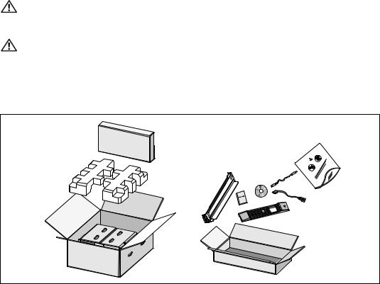
1 Open the outer carton and remove the accessories packaged with the cabinet (see Figure 2).
Figure 2. Unpacking the Cabinet
Installation | 13
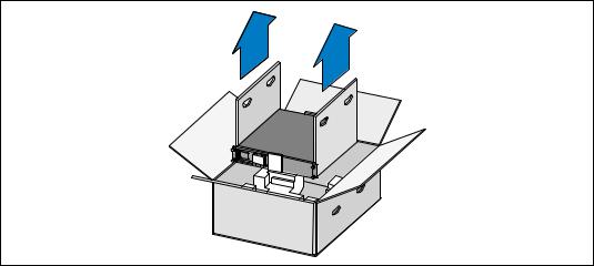
2With one person on each side, carefully lift the cabinet out of the outer carton using the handles on the cardboard and set it on a flat, stable surface (see Figure 3).
Place the cabinet in a protected area that has adequate airflow and is free of humidity, flammable gas, and corrosion.
Figure 3. Lifting the Cabinet
3 Discard or recycle the packaging in a responsible manner, or store it for future use.
14 | Installation
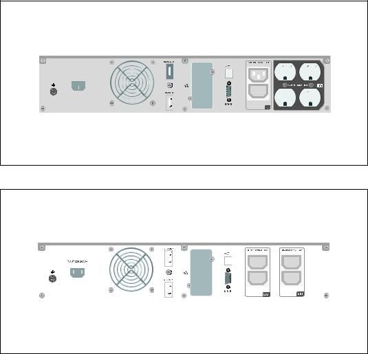
Identifying the UPS Rear Panels
This section shows the rear panels of the Dell Line-Interactive Rack models.
|
|
USB Port |
||||||
|
|
|
|
|
Four 5 15 Receptacles |
|||
UPS Communication Bay |
|
|
|
(Load Segment 1) |
||||
|
|
|
|
|
|
|
|
|
|
|
|
|
|
|
|
|
|
|
|
|
|
|
|
|
|
|
|
|
|
|
|
|
|
|
|
|
|
|
|
|
|
|
|
|
IN PU T 100−120 V ~
|
|
|
|
|
|
|
|
|
|
|
|
|
|
|
|
|
|
|
|
|
|
|
|
|
|
|
|
|
|
|
|
|
|
|
|
|
|
|
|
|
|
|
|
|
|
|
|
|
|
|
|
|
|
|
|
|
|
|
|
|
|
|
|
|
|
|
|
|
|
|
|
|
|
|
|
|
|
|
|
|
|
|
|
|
|
|
|
|
|
|
|
|
|
|
|
|
|
|
|
|
|
|
|
|
|
|
|
|
|
|
|
|
|
|
|
|
|
|
|
|
|
|
|
|
|
|
|
|
|
|
|
|
|
|
|
|
|
|
|
|
|
|
|
|
|
|
|
|
|
Ground Screw |
IEC-C14 Input |
REPO Ports |
RS-232 Port |
|
Two IEC 320-C13 Receptacles |
|||||||||||||||||||
|
|
|
|
|
|
|
Connector |
|
|
|
|
|
(Load Segment 2) |
|||||||||||
Figure 4. 1000W, 100V/120V Rear Panel
|
|
|
|
|
|
|
|
USB Port |
|
|
|
|
Two IEC 320-C13 |
|||
|
|
|
|
|
|
|
|
|
|
|
|
Receptacles |
||||
|
|
|
|
|
|
|
|
|
|
|
|
|
|
|||
|
|
|
|
UPS Communication Bay |
|
|
|
|
|
|
(Load Segment 1) |
|||||
|
|
|
|
|
|
|
|
|
|
|
|
|
|
|
|
|
|
|
|
|
|
|
|
|
|
|
|
|
|
|
|
|
|
|
|
|
|
|
|
|
|
|
|
|
|
|
|
|
|
|
|
|
|
|
|
|
|
|
|
|
|
|
|
|
|
|
|
|
|
|
|
|
|
|
|
|
|
|
|
|
|
|
|
|
|
|
|
|
|
|
|
|
|
|
|
|
|
|
|
|
|
|
|
|
|
|
|
|
|
|
|
|
|
|
|
|
|
|
|
|
|
|
|
|
|
|
|
|
|
|
|
|
|
|
|
|
|
|
|
|
|
|
|
|
|
|
|
|
|
|
|
|
|
|
|
|
|
|
|
|
|
|
|
|
|
|
|
|
|
|
|
|
|
|
|
|
|
|
|
|
|
|
|
|
|
|
Ground Screw |
IEC-C14 Input |
REPO Ports |
RS-232 Port |
Two IEC 320-C13 Receptacles |
|
Connector |
|
|
(Load Segment 2) |
Figure 5. 1000W, 230V Rear Panel
Installation | 15
|
REPO Ports |
UPS Communication Bay |
|
|
|
|
|
|
|
|
|
|
|
|
|
Six 5-15/5-20 and Two |
|||||||||||
|
|
|
EBM Connector Cover/Strain |
IEC 320-C19 Receptacles |
|||||||||||||||||||||||
|
|
|
|
|
|
|
|
|
|
|
|||||||||||||||||
Ground Screw |
USB Port |
|
|
|
|
Relief Bracket |
(Load Segment 1) |
||||||||||||||||||||
|
|
|
|
|
|
|
|
|
|
|
|
|
|
|
|
|
|
|
|
||||||||
|
|
|
|
|
|
|
|
|
|
|
|
|
|
|
|
|
|
|
|
|
|
|
|
|
|
|
|
|
|
|
|
|
|
|
|
|
|
|
|
|
|
|
|
|
|
|
|
|
|
|
|
|
|
|
|
|
|
|
|
|
|
|
|
|
|
|
|
|
|
|
|
|
|
|
|
|
|
|
|
|
|
|
|
|
|
|
|
|
|
|
|
|
|
|
|
|
|
|
|
|
|
|
|
|
|
|
|
|
|
|
|
|
|
|
|
|
|
|
|
|
|
|
|
|
|
|
|
|
|
|
|
|
|
|
|
|
|
|
|
|
|
|
|
|
|
|
|
|
|
|
|
|
|
|
|
|
|
|
|
|
|
|
|
|
|
|
|
|
|
|
|
|
|
|
|
|
|
|
|
|
|
|
|
|
|
|
|
|
|
|
|
|
|
|
|
|
|
|
|
|
|
|
|
|
|
|
|
|
|
|
|
|
|
|
|
|
|
|
|
|
|
|
|
|
|
|
|
|
|
|
|
|
|
|
|
|
|
|
|
|
|
|
|
|
|
|
|
|
|
|
|
|
|
|
|
|
|
|
|
|
|
|
|
|
|
|
|
|
|
|
|
|
|
|
|
|
|
|
|
|
|
|
|
|
|
|
|
|
|
|
|
|
|
|
|
|
|
|
|
|
|
|
|
|
|
|
|
|
|
|
|
|
|
|
|
|
|
|
|
|
|
|
|
|
|
|
|
|
|
|
|
|
|
|
|
|
|
|
|
|
|
|
|
|
|
|
|
|
|
|
|
|
|
|
|
|
|
|
|
|
|
|
|
|
|
|
|
|
|
|
|
|
|
|
|
|
|
|
|
|
|
|
|
|
|
|
|
|
|
|
|
IEC-C20 Input |
RS-232 Port |
Two IEC 320-C13 Receptacles |
Connector |
|
(Load Segment 2) |
|
|
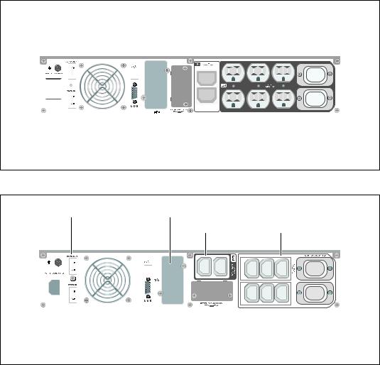
Figure 6. 1920W/120V, 1500W/100V Rear Panel
REPO Ports |
UPS Communication Bay |
Two IEC 320-C13 |
Six IEC 320-C13 |
|
Receptacles |
Receptacles |
|||
|
|
|||
Ground Screw |
USB Port |
(Load Segment 1) |
(Load Segment 2) |
|
|
|
|
|
|
|
|
|
|
|
|
|
|
|
|
|
|
|
|
|
|
|
|
|
|
|
|
|
|
|
|
|
|
|
|
|
|
|
|
|
|
|
|
|
|
|
|
|
|
|
|
|
|
|
|
|
|
|
|
|
|
|
|
|
|
|
|
|
|
|
|
|
|
|
|
|
|
|
|
|
|
|
|
|
|
|
|
|
|
|
|
|
|
|
|
|
|
|
|
|
|
|
|
|
|
|
|
|
|
|
|
|
|
|
|
|
|
|
|
|
|
|
|
|
|
|
|
|
|
|
|
|
|
|
|
|
|
|
|
|
|
|
|
|
|
|
|
|
|
|
|
|
|
|
|
|
|
|
|
|
|
|
|
|
|
|
|
|
|
|
|
|
|
|
|
|
|
|
|
|
|
|
|
|
|
|
|
|
|
|
|
|
|
|
|
|
|
|
|
|
|
|
|
|
|
|
|
|
|
|
|
|
|
|
|
|
|
|
|
|
|
|
|
|
|
|
|
|
|
|
|
|
|
|
|
|
|
|
|
|
|
|
|
|
|
|
|
|
|
|
|
|
|
|
|
|
|
|
|
|
|
|
|
|
|
|
|
|
|
|
|
|
|
|
|
|
|
|
|
|
|
|
|
|
|
|
|
|
|
|
|
|
|
|
|
|
|
|
|
|
|
|
|
|
|
|
|
|
|
|
|
|
|
|
|
|
|
|
|
|
|
|
|
|
|
|
|
|
|
|
|
|
|
|
|
|
|
|
|
|
|
|
|
|
|
|
|
|
|
|
|
|
|
|
|
|
|
|
|
|
|
|
|
|
|
|
|
|
|
|
|
|
|
|
|
|
|
|
|
|
|
|
|
|
|
|
|
|
|
|
|
|
|
|
|
|
|
|
|
|
|
|
|
|
|
|
|
|
|
|
|
|
|
|
|
|
|
|
|
|
|
|
|
|
|
|
|
|
|
|
|
|
|
|
|
|
|
|
|
|
|
|
|
|
|
|
|
|
|
|
|
|
|
|
|
|
|
|
|
|
|
|
|
|
|
|
|
|
|
|
|
|
|
|
|
|
|
|
|
|
|
|
|
|
|
|
|
|
|
|
|
|
|
|
|
|
|
|
|
|
|
|
|
|
|
|
IEC-C14 Input |
|
|
|
RS-232 Port |
EBM Connector Cover/Strain |
|
Two IEC 320-C19 |
||||||||||||||||||||||||||||
Connector |
|
|
|
|
|
|
Relief Bracket |
|
Receptacles |
||||||||||||||||||||||||||
|
|
|
|
|
|
|
|
|
|
|
|
|
|
|
|
|
|
|
|
|
|
|
|
|
|
|
|
|
|
(Load Segment 2) |
|||||
Figure 7. 1920W, 230V Rear Panel
16 | Installation

|
|
|
|
|
|
Output Circuit Breakers |
Two IEC 320-C13 |
EBM Connector |
||||||||||||||||||||||
|
|
|
|
|
|
|
|
|
|
|
||||||||||||||||||||
REPO Ports |
|
|
|
|
|
|
|
Receptacles |
Cover/Strain Relief |
|||||||||||||||||||||
|
|
|
RS-232 Port |
|
(Load Segment 2) |
Bracket |
||||||||||||||||||||||||
|
|
|
|
|
|
|
|
|||||||||||||||||||||||
|
|
|
|
|
|
|
|
|
|
|
|
|
|
|
|
|
|
|
|
|
|
|
|
|
|
|
|
|
|
|
|
|
|
|
|
|
|
|
|
|
|
|
|
|
|
|
|
|
|
|
|
|
|
|
|
|
|
|
|
|
|
|
|
|
|
|
|
|
|
|
|
|
|
|
|
|
|
|
|
|
|
|
|
|
|
|
|
|
|
|
|
|
|
|
|
|
|
|
|
|
|
|
|
|
|
|
|
|
|
|
|
|
|
|
|
|
|
|
|
|
|
|
|
|
|
|
|
|
|
|
|
|
|
|
|
|
|
|
|
|
|
|
|
|
|
|
|
|
|
|
|
|
|
|
|
|
|
|
|
|
|
|
|
|
|
|
|
|
|
|
|
|
|
|
|
|
|
|
|
|
|
|
|
|
|
|
|
|
|
|
|
|
|
|
|
|
|
|
|
|
|
|
|
|
|
|
|
|
|
|
|
|
|
|
|
|
|
|
|
|
|
|
|
|
|
|
|
|
|
|
|
|
|
|
|
|
|
|
|
|
|
|
|
|
|
|
|
|
|
|
|
|
|
|
|
|
|
|
|
|
|
|
|
|
|
|
|
|
|
|
|
|
|
|
|
|
|
|
|
|
|
|
|
|
|
|
|
|
|
|
|
|
|
|
|
|
|
|
|
|
|
|
|
|
|
|
|
|
|
|
|
|
|
|
|
|
|
|
|
|
|
|
|
|
|
|
|
|
|
|
|
|
|
|
|
|
|
|
|
|
|
|
|
|
|
|
|
|
|
|
|
|
|
|
|
|
|
|
|
|
|
|
|
|
|
|
|
|
|
|
|
|
|
|
|
|
|
|
|
|
|
|
|
|
|
|
|
|
|
|
|
|
|
|
|
|
|
|
|
|
|
|
|
|
|
|
|
|
|
|
|
|
|
|
|
|
|
|
|
|
|
|
|
|
|
|
|
|
|
|
|
|
|
|
|
|
|
|
|
|
|
|
|
|
|
|
|
|
|
|
|
|
|
|
|
|
|
|
|
|
|
|
|
|
|
|
|
|
|
|
|
|
|
|
|
|
|
|
|
|
|
|
|
|
|
|
|
|
|
|
|
|
|
|
|
|
|
|
|
|
|
|
|
|
|
|
|
|
|
|
|
|
|
|
|
|
|
|
|
|
|
|
|
|
|
|
|
USB Port |
One L5-20, Two 5-15/5-20, and |
2m, L5-30P Input Cord |
Ground Screw |
Two IEC 320-C19 Receptacles |
UPS |
(Load Segment 1) |
|
Communication |
||
|
||
Bay |
|
Figure 8. 2700W/120V, 2300W/100V Rear Panel
|
|
Two IEC 320-C13 |
EBM Connector |
|
|
Receptacles |
Cover/Strain Relief |
REPO Ports |
USB Port |
(Load Segment 2) |
Bracket |
|
|
|
|
|
|
|
|
|
|
|
|
|
|
|
|
|
|
|
|
|
|
|
|
|
|
|
|
|
|
|
|
|
|
|
|
|
|
|
|
|
|
|
|
|
|
|
|
|
|
|
|
|
|
|
|
|
|
|
|
|
|
|
|
|
|
|
|
|
|
|
|
|
|
|
|
|
|
|
|
|
|
|
|
|
|
|
|
|
|
|
|
|
|
|
|
|
|
|
|
|
|
|
|
|
|
|
|
|
|
|
|
|
|
|
|
|
|
|
|
|
|
|
|
|
|
|
|
|
|
|
|
|
|
|
|
|
|
|
|
|
|
|
|
|
|
|
|
|
|
|
|
|
|
|
|
|
|
|
|
|
|
|
|
|
|
|
|
|
|
|
|
|
|
|
|
|
|
|
|
|
|
|
|
|
|
|
|
|
|
|
|
|
|
|
|
|
|
|
|
|
|
|
|
|
|
|
|
|
|
|
|
|
|
|
|
|
|
|
|
|
|
|
|
|
|
|
|
|
|
|
|
|
|
|
|
|
|
|
|
|
|
|
|
|
|
|
|
|
|
|
|
|
|
|
|
|
|
|
|
|
|
|
|
|
|
|
|
|
|
|
|
|
|
|
|
|
|
|
|
|
|
|
|
|
|
|
|
|
|
|
|
|
|
|
|
|
|
|
|
|
|
|
|
|
|
|
|
|
|
|
|
|
|
|
|
|
|
|
|
|
|
|
|
|
|
|
|
|
|
|
|
|
|
|
|
|
|
|
|
|
|
|
|
|
|
|
|
|
|
|
|
|
|
|
|
|
|
|
|
|
|
|
|
|
|
|
|
|
|
|
|
|
|
|
|
|
|
|
|
|
|
|
|
|
|
|
|
|
|
|
|
|
|
|
|
|
|
|
|
|
|
|
|
|
|
|
|
|
|
|
|
|
|
|
|
|
|
|
|
|
|
|
|
|
|
|
|
|
|
|
|
|
|
|
|
|
|
|
|
|
|
|
|
|
|
|
|
IEC-C20 Input |
Ground Screw |
RS-232 Port |
|
|
|
Two L6-20 and |
|||||||||||||||||||||
Connector |
|
|
|
|
|
|
|
|
|
UPS |
|
|
Two IEC 320-C19 Receptacles |
||||||||||||||
|
|
|
|
|
|
|
|
|
|
|
|
|
|
|
|
||||||||||||
|
|
|
|
|
|
|
|
|
|
|
|
Communication |
|
|
(Load Segment 1) |
||||||||||||
|
|
|
|
|
|
|
|
|
|
|
|
|
|
Bay |
|
|
|
|
|
|
|
|
|
|
|
||
Figure 9. 2700W, 208V Rear Panel
Installation | 17
|
|
|
|
|
|
|
|
|
|
|
|
Two IEC 320-C13 |
EBM Connector |
|||||||||||||
|
|
|
|
|
|
|
|
|
|
|
|
Receptacles |
Cover/Strain Relief |
|||||||||||||
REPO Ports |
|
|
|
|
|
|
|
USB Port |
(Load Segment 2) |
Bracket |
||||||||||||||||
|
|
|
|
|
|
|
|
|
|
|
|
|
|
|
|
|
|
|
|
|
|
|
|
|
|
|
|
|
|
|
|
|
|
|
|
|
|
|
|
|
|
|
|
|
|
|
|
|
|
|
|
|
|
|
|
|
|
|
|
|
|
|
|
|
|
|
|
|
|
|
|
|
|
|
|
|
|
|
|
|
|
|
|
|
|
|
|
|
|
|
|
|
|
|
|
|
|
|
|
|
|
|
|
|
|
|
|
|
|
|
|
|
|
|
|
|
|
|
|
|
|
|
|
|
|
|
|
|
|
|
|
|
|
|
|
|
|
|
|
|
|
|
|
|
|
|
|
|
|
|
|
|
|
|
|
|
|
|
|
|
|
|
|
|
|
|
|
|
|
|
|
|
|
|
|
|
|
|
|
|
|
|
|
|
|
|
|
|
|
|
|
|
|
|
|
|
|
|
|
|
|
|
|
|
|
|
|
|
|
|
|
|
|
|
|
|
|
|
|
|
|
|
|
|
|
|
|
|
|
|
|
|
|
|
|
|
|
|
|
|
|
|
|
|
|
|
|
|
|
|
|
|
|
|
|
|
|
|
|
|
|
|
|
|
|
|
|
|
|
|
|
|
|
|
|
|
|
|
|
|
|
|
|
|
|
|
|
|
|
|
|
|
|
|
|
|
|
|
|
|
|
|
|
|
|
|
|
|
|
|
|
|
|
|
|
|
|
|
|
|
|
|
|
|
|
|
|
|
|
|
|
|
|
|
|
|
|
|
|
|
|
|
|
|
|
|
|
|
|
|
|
|
|
|
|
|
|
|
|
|
|
|
|
|
|
|
|
|
|
|
|
|
|
|
|
|
|
|
|
|
|
|
|
|
|
|
|
|
|
|
|
|
|
|
|
|
|
|
|
|
|
|
|
|
|
|
|
|
|
|
|
|
|
|
|
|
|
|
|
|
|
|
|
|
|
|
|
|
|
|
|
|
|
|
|
|
|
|
|
|
|
|
|
|
|
|
|
|
|
|
|
|
|
|
|
|
|
|
|
|
|
|
|
|
|
|
|
|
|
|
|
|
|
|
|
|
|
|
|
|
|
|
|
|
|
IEC-C20 Input |
Ground Screw |
RS-232 Port |
Six IEC 320-C13 and |
Connector |
|
UPS |
Two IEC 320-C19 Receptacles |
|
|
||
|
|
Communication |
(Load Segment 1) |
|
|
Bay |
|
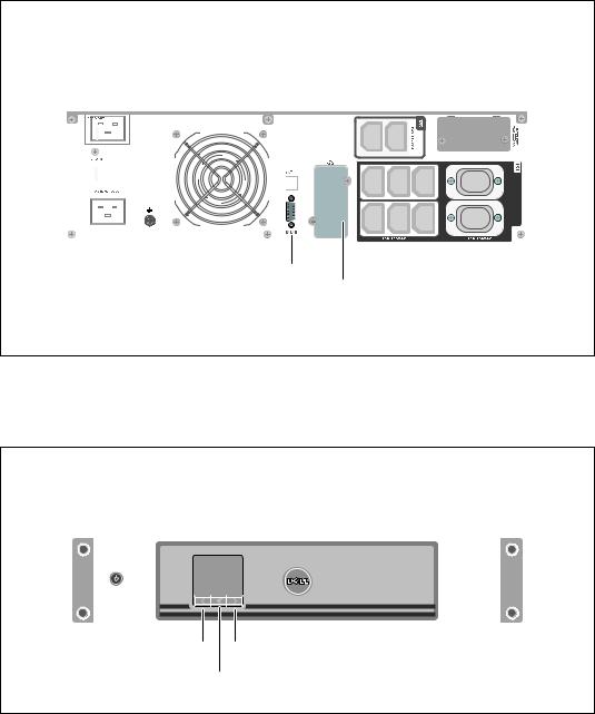
Figure 10. 2700W, 230V Rear Panel
Identifying the UPS Front Panel
On/Off Button |
|
LCD Panel |
|||||||
|
|
|
|
|
|
|
|
|
|
|
|
|
|
|
|
|
|
|
|
|
|
|
|
|
|
|
|
|
|
|
|
|
|
|
|
|
|
|
|
|
|
|
|
|
|
|
|
|
|
|
|
|
|
|
|
|
|
|
|
|
|
|
|
|
|
|
|
|
|
|
|
|
|
|
|
|
|
|
|
|
|
|
|
|
|
|
|
|
|
|
|
|
|
|
|
|
|
|
|
|
|
|
|
|
|
|
|
|
|
Scroll Button (Up or Back) |
Scroll Button (Down or Forward) |
Select Button
Figure 11. The Dell Line-Interactive Rack UPS Front Panel
18 | Installation
UPS Setup
The Dell Line-Interactive Rack UPS can be installed in 19-inch racks and needs only 2U of valuable rack space (3U for 2700/2300W UPS models).
NOTE: No tools are needed to attach the rack rails to a roundor square-hole EIA rack.
The 2700/2300W UPS models are designed for flexible configurations and can be installed in a rack or as a standalone cabinet.
If you are installing the UPS in a rack, continue to the following section, “Rackmount Setup.” To install the 2700/2300W UPS as a standalone cabinet, continue to “Tower Setup” on page 24.
Rackmount Setup
CAUTION: The cabinet is heavy (see page 65): 1) Dell strongly recommends to remove the battery tray from the UPS before lifting. 2) Lifting the cabinets into the rack requires a minimum of two people.
CAUTION: Removing the batteries should be performed or supervised by personnel knowledgeable about batteries and the required precautions. Keep unauthorized personnel away from batteries.
CAUTION: If installing an optional EBM, install the EBM directly below the UPS.
NOTE: Mounting rails are required for each individual cabinet.
To install the UPS and optional EBM in a rack:
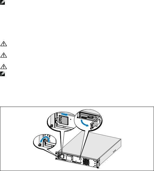
1Remove the internal battery tray from the UPS:
Loosen the thumbscrew on the metal battery cover, slide the cover to the right, and open (see Figure 12).
Figure 12. Opening the Metal Battery Cover
Installation | 19
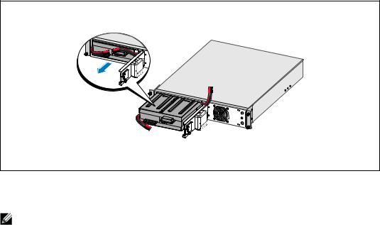
Unclip the right battery connector and move the connector out of the way.
Pull the battery tray out using the plastic tabs and remove the battery tray (see Figure 13).
Figure 13. Removing the Battery Tray
2 If installing additional UPSs, repeat Step 1 for each cabinet.
NOTE: The instructions are the same for square-hole racks and unthreaded, round-hole racks. The rails fit both rack styles. The square-hole rack is shown in the illustrations.
3Select the proper holes in the rail for positioning the cabinet in the desired location in the rack.
The rails should be located at the bottom of the 2U (or 3U for 2700/2300W UPS models) space allocated for the UPS or EBM.
4Position the end of the left and right rails labeled FRONT facing inward.
20 | Installation
5Attach the rails to the rack:
Engage the back end of the rail until it fully seats on the vertical rack flange and the hook latch locks in place (see Figure 14).
Pull the rail toward the front.
Push the front end of the rail until it fully seats on the vertical rack flange and the hook latch locks in place.
Figure 14. Installing the Rails
Installation | 21
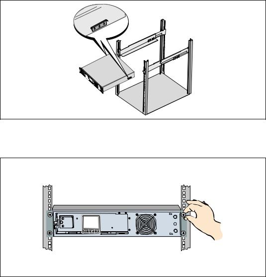
6 Slide the cabinet into the rack (see Figure 15). Repeat for any additional cabinets.
Figure 15. Installing the Cabinet
7Secure the front of the cabinet to the rack using the four thumbscrews on the mounting brackets (see Figure 16). Tighten by hand; do not use power tools. Repeat for any additional cabinets.
Figure 16. Securing the Cabinet
22 | Installation
Loading...