


Prestige 314
P314 Broadband Sharing Gateway with 4-Port Switch
User’s Guide
Version 3.20
August 2000

P314 Broadband Sharing Gateway with 4-Port Switch
Prestige 314
P314 Broadband Sharing Gateway With 4-Port Switch
Copyright
Copyright © 2000 by ZyXEL Communications Corporation.
The contents of this publication may not be reproduced in any part or as a whole, transcribed, stored in a retrieval system, translated into any language, or transmitted in any form or by any means, electronic, mechanical, magnetic, optical, chemical, photocopying, manual, or otherwise, without the prior written permission of ZyXEL Communications Corporation.
Published by ZyXEL Communications Corporation. All rights reserved.
Disclaimer
ZyXEL does not assume any liability arising out of the application or use of any products, or software described herein. Neither does it convey any license under its patent rights nor the patent rights of others. ZyXEL further reserves the right to make changes in any products described herein without notice. This publication is subject to change without notice.
Trademarks
Trademarks mentioned in this publication are used for identification purposes only and may be properties of their respective owners.
ii |
Copyright |

P314 Broadband Sharing Gateway With 4-Port Switch
Federal Communications Commission (FCC) Interference Statement
This device complies with Part 15 of FCC rules. Operation is subject to the following two conditions:
This device may not cause harmful interference.
This device must accept any interference received, including interference that may cause undesired operations.
This equipment has been tested and found to comply with the limits for a class B digital device pursuant to Part 15 of the FCC Rules. These limits are designed to provide reasonable protection against harmful interference in a commercial environment. This equipment generates, uses, and can radiate radio frequency energy, and if not installed and used in accordance with the instructions, may cause harmful interference to radio communications.
If this equipment does cause harmful interference to radio/television reception, which can be determined by turning the equipment off and on, the user is encouraged to try to correct the interference by one or more of the following measures:
Reorient or relocate the receiving antenna.
Increase the separation between the equipment and the receiver.
Connect the equipment into an outlet on a circuit different from that to which the receiver is connected.
Consult the dealer or an experienced radio/TV technician for help.
Notice 1
Changes or modifications not expressly approved by the party responsible for compliance could void the user's authority to operate the equipment.
Notice 2
Shielded RS-232 cables are required to be used to ensure compliance with FCC Part 15, and it is the responsibility of the user to provide and use shielded RS-232 cables.
FCC Statement |
iii |

P314 Broadband Sharing Gateway with 4-Port Switch
Information for Canadian Users
The Industry Canada label identifies certified equipment. This certification means that the equipment meets certain telecommunications network protective, operation, and safety requirements. The Industry Canada does not guarantee that the equipment will operate to a user's satisfaction.
Before installing this equipment, users should ensure that it is permissible to be connected to the facilities of the local telecommunications company. The equipment must also be installed using an acceptable method of connection. In some cases, the company's inside wiring associated with a single line individual service may be extended by means of a certified connector assembly. The customer should be aware that the compliance with the above conditions may not prevent degradation of service in some situations.
Repairs to certified equipment should be made by an authorized Canadian maintenance facility designated by the supplier. Any repairs or alterations made by the user to this equipment, or equipment malfunctions, may give the telecommunications company cause to request the user to disconnect the equipment.
For their own protection, users should ensure that the electrical ground connections of the power utility, telephone lines, and internal metallic water pipe system, if present, are connected together. This precaution may be particularly important in rural areas.
Caution
Users should not attempt to make such connections themselves, but should contact the appropriate electrical inspection authority or electrician, as appropriate.
Note
This digital apparatus does not exceed the class A limits for radio noise emissions from digital apparatus set out in the radio interference regulations of Industry Canada.
iv |
Canadian Users |

P314 Broadband Sharing Gateway With 4-Port Switch
Declaration of Conformity
We, the Manufacturer/Importer,
ZyXEL Communications Corp.
No. 6, Innovation Rd. II,
Science-Based Industrial Park,
Hsinchu, Taiwan, 300 R.O.C
Standard
•EN 55022
•EN 61000-3-2
declare that the product
Prestige 314
is in conformity with
(reference to the specification under which conformity is declared)
Standard Item |
Version |
Radio disturbance characteristics – Limits and method of |
1994 |
measurement. |
|
Disturbance in supply system caused by household appliances |
1995 |
and similar electrical equipment “Harmonics”. |
|
•EN 61000-3-3
•EN 61000-4-2
•EN 61000-4-3
•EN 61000-4-4
•EN 61000-4-5
•EN 61000-4-6
•EN 61000-4-8
•EN 61000-4-11
Disturbance in supply system caused by household appliances |
1995 |
and similar electrical equipment “Voltage fluctuations”. |
|
Electrostatic discharge immunity test – Basic EMC Publication |
1995 |
Radiated, radio-frequency, electromagnetic field immunity test |
1996 |
Electrical fast transient / burst immunity test – Basic EMC |
1995 |
Publication |
|
Surge immunity test |
1995 |
Immunity to conducted disturbances, induced by radio-frequency |
1996 |
fields |
|
|
1993 |
Voltage dips, short interruptions and voltage variations immunity |
1994 |
tests |
|
Declaration of Conformity |
v |

P314 Broadband Sharing Gateway with 4-Port Switch
vi |
CE Doc |

P314 Broadband Sharing Gateway With 4-Port Switch
ZyXEL Limited Warranty
ZyXEL warrants to the original end user (purchaser) that this product is free from any defects in materials or workmanship for a period of up to two years from the date of purchase. During the warranty period, and upon proof of purchase, should the product have indications of failure due to faulty workmanship and/or materials, ZyXEL will, at its discretion, repair or replace the defective products or components without charge for either parts or labor, and to whatever extent it shall deem necessary to restore the product or components to proper operating condition. Any replacement will consist of a new or re-manufactured functionally equivalent product of equal value, and will be solely at the discretion of ZyXEL. This warranty shall not apply if the product is modified, misused, tampered with, damaged by an act of God, or subjected to abnormal working conditions.
Note
Repair or replacement, as provided under this warranty, is the exclusive remedy of the purchaser. This warranty is in lieu of all other warranties, express or implied, including any implied warranty of merchantability or fitness for a particular use or purpose. ZyXEL shall in no event be held liable for indirect or consequential damages of any kind of character to the purchaser.
To obtain the services of this warranty, contact ZyXEL's Service Center; refer to the separate Warranty Card for your Return Material Authorization number (RMA). Products must be returned Postage Prepaid. It is recommended that the unit be insured when shipped. Any returned products without proof of purchase or those with an out-dated warranty will be repaired or replaced (at the discretion of ZyXEL) and the customer will be billed for parts and labor. All repaired or replaced products will be shipped by ZyXEL to the corresponding return address, Postage Paid (USA and territories only). If the customer desires some other return destination beyond the U.S. borders, the customer shall bear the cost of the return shipment. This warranty gives you specific legal rights, and you may also have other rights that vary from state to state.
Please register your Prestige (fast, easy online registration at www.zyxel.com) for free product updates and information.
Warranty |
vii |

P314 Broadband Sharing Gateway with 4-Port Switch
Customer Support
If you have questions about your ZyXEL product or desire assistance, contact ZyXEL Communications Corporation offices worldwide, in one of the following ways:
Method |
EMAIL – Support |
Telephone |
Web Site |
Regular Mail |
|
|
|||||
Region |
|
|
|
||
EMAIL – Sales |
Fax |
FTP Site |
|
||
|
support@zyxel.com.tw |
+886-3-578-3942 |
www.zyxel.com |
|
|
|
support@europe.zyxel.com |
|
www.europe.zyxel.com |
ZyXEL Communications |
|
Worldwide |
|
|
|
Corp., 6 Innovation Road II, |
|
|
|
|
Science-Based Industrial |
||
|
|
|
|
||
|
sales@zyxel.com.tw |
+886-3-578-2439 |
ftp.europe.zyxel.com |
Park, HsinChu, Taiwan. |
|
|
|
||||
|
|
|
|
|
|
|
support@zyxel.com |
+1-714-632-0882 |
www.zyxel.com |
ZyXEL Communications Inc., |
|
North |
|
800-255-4101 |
|
||
|
|
1650 Miraloma Avenue, |
|||
America |
sales@zyxel.com |
+1-714-632-0858 |
ftp.zyxel.com |
||
Placentia, CA 92870, U.S.A. |
|||||
|
|||||
|
|
|
|
|
|
|
support@zyxel.dk |
+45-3955-0700 |
www.zyxel.dk |
ZyXEL Communications A/S, |
|
Scandinavia |
|
|
|
||
sales@zyxel.dk |
+45-3955-0707 |
ftp.zyxel.dk |
Columbusvej 5, 2860 |
||
|
Soeborg, Denmark. |
||||
|
|
|
|
||
|
|
|
|
|
|
|
support@zyxel.at |
+43-1-4948677-0 |
www.zyxel.at |
|
|
|
|
0810-1-ZyXEL |
|
ZyXEL Communications |
|
Austria |
|
0810-1-99935 |
|
Services GmbH., |
|
sales@zyxel.at |
|
ftp.zyxel.at |
Thaliastrasse 125a/2/2/4, |
||
|
|
||||
|
+43-1-4948678 |
A-1160 Vienna, Austria |
|||
|
|
Note: for Austrian users with *.at |
|||
|
|
|
domain only! |
|
|
|
support@zyxel.de |
+49-2405-6909-0 |
www.zyxel.de |
|
|
|
|
|
|
||
|
|
0180-5213247 |
|
ZyXEL Deutschland GmbH., |
|
Germany |
|
Tech Support hotline |
|
||
|
|
Adenauerstr. 20/A4, D-52146 |
|||
|
0180-5099935 |
|
|||
|
|
|
Wuerselen, Germany. |
||
|
|
RMA/Repair hotline |
|
||
|
|
|
|
||
|
sales@zyxel.de |
+49-2405-6909-99 |
ftp.europe.zyxel.com |
|
|
|
|
|
|
|
|
|
|
|
|
|
viii |
Customer Support |
|
P314 Broadband Sharing Gateway with 4-Port Switch |
|
|
Table of Contents |
|
Customer Support ........................................................................................................................ |
viii |
|
Table of Contents ........................................................................................................................... |
ix |
|
List of Figures............................................................................................................................... |
xiii |
|
List of Tables ............................................................................................................................... |
xvii |
|
Preface ......................................................................................................................................... |
|
xix |
Getting Started ................................................................................................................................... |
I |
|
Chapter 1 Getting to Know Your Prestige..................................................................................... |
1-1 |
|
1.1 |
The Prestige 314 Broadband Sharing Gateway With 4-Port Switch........................................... |
1-1 |
1.2 |
Features of the Prestige 314........................................................................................................ |
1-1 |
1.3 |
Broadband Internet Access via Cable or DSL Modem............................................................... |
1-2 |
Chapter 2 Hardware Installation & Initial Setup............................................................................ |
2-1 |
|
2.1 |
Front Panel LEDs and Back Panel Ports..................................................................................... |
2-1 |
2.1.1 |
Front Panel LEDs................................................................................................................ |
2-1 |
2.2 |
Prestige 314 Rear Panel and Connections................................................................................... |
2-2 |
2.3 |
Additional Installation Requirements ......................................................................................... |
2-3 |
2.4 |
Power Up Your Prestige ............................................................................................................. |
2-4 |
2.5 |
Navigating the SMT Interface .................................................................................................... |
2-4 |
2.5.1 |
Main Menu.......................................................................................................................... |
2-5 |
2.5.2 |
System Management Terminal Interface Summary............................................................ |
2-6 |
2.6 |
Changing the System Password .................................................................................................. |
2-7 |
2.6.1 |
Resetting the Prestige.......................................................................................................... |
2-7 |
2.7 |
General Setup.............................................................................................................................. |
2-7 |
2.7.1 |
Dynamic DNS..................................................................................................................... |
2-8 |
2.7.2 |
Configuring Dynamic DNS ................................................................................................ |
2-9 |
2.8 |
WAN Setup............................................................................................................................... |
2-10 |
2.9 |
LAN Setup ................................................................................................................................ |
2-11 |
2.9.1 |
LAN Port Filter Setup....................................................................................................... |
2-11 |
Chapter 3 Internet Access ............................................................................................................ |
3-1 |
|
3.1 |
TCP/IP and DHCP for LAN ....................................................................................................... |
3-1 |
|
|
|
Table of Contents |
ix |
|

P314 Broadband Sharing Gateway with 4-Port Switch
3.1.1 |
Factory LAN Defaults ........................................................................................................ |
3-1 |
|
3.1.2 |
IP Address and Subnet Mask.............................................................................................. |
3-1 |
|
3.1.3 |
Private IP Addresses........................................................................................................... |
3-2 |
|
3.1.4 |
RIP Setup............................................................................................................................ |
3-2 |
|
3.1.5 |
DHCP Configuration .......................................................................................................... |
3-3 |
|
3.1.6 |
IP Multicast ........................................................................................................................ |
3-3 |
|
3.2 |
TCP/IP and DHCP Ethernet Setup ............................................................................................. |
3-4 |
|
3.3 |
Internet Access Setup ................................................................................................................. |
3-6 |
|
3.3.1 |
Ethernet Encapsulation ....................................................................................................... |
3-6 |
|
3.3.2 |
PPPoE Encapsulation ......................................................................................................... |
3-8 |
|
3.4 |
Internet Setup Test...................................................................................................................... |
3-9 |
|
3.5 |
Basic Setup Complete................................................................................................................. |
3-9 |
|
Advanced Applications.................................................................................................................... |
II |
||
Chapter 4 |
Remote Node Setup..................................................................................................... |
4-1 |
|
4.1 |
Remote Node Profile .................................................................................................................. |
4-1 |
|
4.1.1 |
Ethernet Encapsulation ....................................................................................................... |
4-1 |
|
4.1.2 |
PPPoE Encapsulation ......................................................................................................... |
4-3 |
|
4.2 |
Editing TCP/IP Options.............................................................................................................. |
4-4 |
|
4.3 |
Remote Node Filter .................................................................................................................... |
4-5 |
|
Chapter 5 |
IP Static Route Setup................................................................................................... |
5-1 |
|
5.1 |
IP Static Route Setup.................................................................................................................. |
5-2 |
|
Chapter 6 |
SUA Server Setup........................................................................................................ |
6-1 |
|
6.1 |
Single User Account (SUA) ....................................................................................................... |
6-1 |
|
6.1.1 |
Single User AccountConfiguration..................................................................................... |
6-2 |
|
6.2 |
Multiple Servers behind SUA..................................................................................................... |
6-3 |
|
6.2.1 |
Configuring a Server behind SUA...................................................................................... |
6-4 |
|
Advanced Management .................................................................................................................. |
III |
||
Chapter 7 |
Filter Configuration....................................................................................................... |
7-1 |
|
7.1 |
About Filtering ........................................................................................................................... |
7-1 |
|
7.1.1 |
The Filter Structure of the Prestige..................................................................................... |
7-2 |
|
7.2 |
Configuring a Filter Set .............................................................................................................. |
7-4 |
|
7.2.1 |
Filter Rules Summary Menu............................................................................................... |
7-6 |
|
7.2.2 |
Configuring a Filter Rule.................................................................................................... |
7-7 |
|
|
|
|
|
x |
|
Table of Contents |
|
P314 Broadband Sharing Gateway with 4-Port Switch
7.2.3 |
TCP/IP Filter Rule .............................................................................................................. |
7-7 |
|
7.2.4 |
Generic Filter Rule............................................................................................................ |
7-11 |
|
7.3 |
|
Example Filter .......................................................................................................................... |
7-13 |
7.4 |
Filter Types and SUA ............................................................................................................... |
7-15 |
|
7.5 |
Applying a Filter and Factory Defaults..................................................................................... |
7-16 |
|
7.5.1 |
LAN Traffic ...................................................................................................................... |
7-16 |
|
7.5.2 |
Remote Node Filters ......................................................................................................... |
7-17 |
|
Chapter 8 |
System Information and Diagnosis .............................................................................. |
8-1 |
|
8.1 |
|
System Status.............................................................................................................................. |
8-2 |
8.2 |
System Information and Console Port Speed ............................................................................. |
8-4 |
|
8.2.1 |
System Information............................................................................................................. |
8-4 |
|
8.2.2 |
Console Port Speed............................................................................................................. |
8-5 |
|
8.3 |
|
Log and Trace............................................................................................................................. |
8-5 |
8.3.1 |
Viewing Error Log.............................................................................................................. |
8-5 |
|
8.3.2 |
UNIX Syslog....................................................................................................................... |
8-6 |
|
8.3.3 |
Call-Triggering Packet........................................................................................................ |
8-9 |
|
8.4 |
|
Diagnostic ................................................................................................................................. |
8-10 |
8.4.1 |
WAN DHCP ..................................................................................................................... |
8-11 |
|
Chapter 9 |
Transferring Files ......................................................................................................... |
9-1 |
|
9.1 |
|
Filename Conventions ................................................................................................................ |
9-1 |
9.1.1 |
Firmware Development ...................................................................................................... |
9-2 |
|
9.2 |
|
Backup Configuration................................................................................................................. |
9-2 |
9.3 |
|
Restore Configuration................................................................................................................. |
9-4 |
9.4 |
|
Upload Firmware ........................................................................................................................ |
9-4 |
9.4.1 |
Uploading the Router Firmware ......................................................................................... |
9-5 |
|
9.4.2 |
Uploading Router Configuration File ................................................................................. |
9-6 |
|
9.5 |
|
TFTP File Transfer ..................................................................................................................... |
9-7 |
9.5.1 |
Example TFTP Command .................................................................................................. |
9-7 |
|
9.6 |
|
FTP File Transfer........................................................................................................................ |
9-8 |
9.6.1 |
Using the FTP Command from the DOS Prompt ............................................................... |
9-9 |
|
Chapter 10 System Maintenance & Information ......................................................................... |
10-1 |
||
10.1 |
|
Command Interpreter Mode...................................................................................................... |
10-1 |
10.2 |
|
Call Control Support................................................................................................................. |
10-2 |
|
|
||
Table of Contents |
xi |
||

P314 Broadband Sharing Gateway with 4-Port Switch
10.2.1 |
Budget Management......................................................................................................... |
10-2 |
|
10.2.2 |
Call History ...................................................................................................................... |
10-3 |
|
10.3 |
Boot Commands ....................................................................................................................... |
10-4 |
|
Chapter 11 Telnet Configuration and Capabilities....................................................................... |
11-1 |
||
11.1 |
About Telnet Configuration...................................................................................................... |
11-1 |
|
11.2 |
Telnet Under SUA.................................................................................................................... |
11-1 |
|
11.3 |
Telnet Capabilities.................................................................................................................... |
11-1 |
|
11.3.1 |
Single Administrator......................................................................................................... |
11-1 |
|
11.3.2 |
System Timeout................................................................................................................ |
11-2 |
|
11.3.3 |
Telnet Blocking ................................................................................................................ |
11-2 |
|
Troubleshooting, Appendices, Glossary and Index .................................................................... |
IV |
||
Chapter 12 Troubleshooting........................................................................................................ |
12-1 |
||
12.1 |
Problems Starting Up the Prestige............................................................................................ |
12-1 |
|
12.2 |
Problems with the LAN Interface............................................................................................. |
12-2 |
|
12.3 |
Problems with the WAN Interface ........................................................................................... |
12-3 |
|
12.4 |
Problems with Internet Access ................................................................................................. |
12-4 |
|
12.5 |
Problems with Telnet................................................................................................................ |
12-4 |
|
Appendix A |
PPPoE...................................................................................................................... |
A |
Appendix B |
Hardware Specifications .......................................................................................... |
C |
Appendix C |
Important Safety Instructions ................................................................................... |
E |
Appendix D Power Adapter Specs.............................................................................................. |
F |
|
Glossary of Terms .......................................................................................................................... |
H |
|
Index............................................................................................................................................... |
|
O |
xii |
Table of Contents |

P314 Broadband Sharing Gateway with 4-Port Switch
|
|
List of Figures |
Figure 1-1 |
Internet Access ....................................................................................................................... |
1-3 |
Figure 2-1 |
Front Panel.............................................................................................................................. |
2-1 |
Figure 2-2 |
Prestige Rear Panel and Connections ..................................................................................... |
2-2 |
Figure 2-3 |
Initial Screen........................................................................................................................... |
2-4 |
Figure 2-4 |
Password Screen ..................................................................................................................... |
2-4 |
Figure 2-5 |
Prestige 314 Main Menu......................................................................................................... |
2-6 |
Figure 2-6 |
Menu 23 – System Security.................................................................................................... |
2-7 |
Figure 2-7 |
Menu 1 – General Setup ......................................................................................................... |
2-8 |
Figure 2-8 |
Configure Dynamic DNS ....................................................................................................... |
2-9 |
Figure 2-9 |
Menu 2 – WAN Setup........................................................................................................... |
2-10 |
Figure 2-10 |
Menu 3 – LAN Setup........................................................................................................... |
2-11 |
Figure 2-11 |
Menu 3.1 – LAN Port Filter Setup ....................................................................................... |
2-11 |
Figure 3-1 |
Menu 3 – LAN Setup (10/100 Mbps Ethernet) ..................................................................... |
3-4 |
Figure 3-2 |
Menu 3.2 – TCP/IP and DHCP Ethernet Setup ...................................................................... |
3-5 |
Figure 3-3 |
Menu 4 – Internet Access Setup ............................................................................................. |
3-7 |
Figure 3-4 |
Menu 4 Using PPPoE ............................................................................................................. |
3-9 |
Figure 4-1 |
Menu 11.1 Remote Node Profile for Ethernet Encapsulation................................................. |
4-1 |
Figure 4-2 |
Menu 11.1 Remote Node Profile for PPPoE Encapsulation ................................................... |
4-3 |
Figure 4-3 |
Remote Node Network Layer Options ................................................................................... |
4-4 |
Figure 4-4 |
Remote Node Filter (Ethernet Encapsulation)........................................................................ |
4-6 |
Figure 4-5 |
Remote Node Filter (PPPoE Encapsulation) .......................................................................... |
4-6 |
Figure 5-1 |
Example of Static Routing Topology...................................................................................... |
5-1 |
Figure 5-2 |
Menu 12 – IP Static Route Setup............................................................................................ |
5-2 |
Figure 5-3 |
Menu 12. 1 – Edit IP Static Route .......................................................................................... |
5-2 |
Figure 6-1 |
An Example of Single User Account Topology...................................................................... |
6-1 |
Figure 6-2 |
Menu 4 – Internet Access Setup for Single User Account...................................................... |
6-2 |
|
|
|
List of Figures |
xiii |
|
P314 |
Broadband Sharing Gateway with 4-Port Switch |
|
|
|
Figure |
6-3 |
Menu 15 ................................................................................................................................. |
6-4 |
|
Figure |
7-1 |
Outgoing Packet Filtering Process ......................................................................................... |
7-1 |
|
Figure |
7-2 |
Filter Rule Process ................................................................................................................. |
7-3 |
|
Figure |
7-3 |
Menu 21 – Filter Set Configuration........................................................................................ |
7-4 |
|
Figure |
7-4 |
NetBIOS_WAN Filter Rules Summary.................................................................................. |
7-5 |
|
Figure |
7-5 |
NetBIOS _LAN Filter Rules Summary.................................................................................. |
7-5 |
|
Figure |
7-6 |
Tel_FTP_Web_WAN Filter Rules Summary.......................................................................... |
7-5 |
|
Figure |
7-7 |
Menu 21.1.1.1 – TCP/IP Filter Rule....................................................................................... |
7-8 |
|
Figure |
7-8 |
Executing an IP Filter........................................................................................................... |
7-10 |
|
Figure |
7-9 |
Menu 21.4.1 – Generic Filter Rule........................................................................................ |
7-11 |
|
Figure |
7-10 |
Telnet Filter Example ........................................................................................................... |
7-13 |
|
Figure |
7-11 |
Example Filter ...................................................................................................................... |
7-14 |
|
Figure |
7-12 |
Example Filter Rules Summary – Menu 21.3 ...................................................................... |
7-15 |
|
Figure |
7-13 |
Protocol and Device Filter Sets ............................................................................................ |
7-16 |
|
Figure |
7-14 |
Filtering LAN Traffic ........................................................................................................... |
7-16 |
|
Figure |
7-15 |
Filtering Remote Node Traffic ............................................................................................. |
7-17 |
|
Figure |
8-1 |
Menu 24 – System Maintenance ............................................................................................ |
8-1 |
|
Figure |
8-2 |
Menu 24.1 – System Maintenance – Status............................................................................ |
8-2 |
|
Figure |
8-3 |
Menu 24.2 – System Information and Console Port Speed.................................................... |
8-4 |
|
Figure 8-4 |
Menu 24.2.1 – System Maintenance – Information ............................................................... |
8-4 |
||
Figure |
8-5 |
Menu 24.2.2 – System Maintenance – Change Console Port Speed...................................... |
8-5 |
|
Figure |
8-6 |
Examples of Error and Information Messages ....................................................................... |
8-6 |
|
Figure |
8-7 |
Examples of Error and Information Messages ....................................................................... |
8-6 |
|
Figure |
8-8 |
Menu 24.3.2 – System Maintenance – UNIX Syslog............................................................. |
8-7 |
|
Figure |
8-9 |
Call-Triggering Packet Example .......................................................................................... |
8-10 |
|
Figure |
8-10 |
Menu 24.4 – System Maintenance – Diagnostic ................................................................. |
8-11 |
|
Figure |
8-11 |
WAN & LAN DHCP............................................................................................................ |
8-12 |
|
Figure |
9-1 |
Menu 24.5 – System Maintenance – Backup Configuration (Console Port).......................... |
9-3 |
|
|
|
|
|
|
xiv |
|
|
List of Figures |
|

P314 Broadband Sharing Gateway with 4-Port Switch
Figure 9-2 |
Menu 24.5 – System Maintenance – Backup Configuration (Telnet)..................................... |
9-3 |
Figure 9-3 |
Menu 24.6 – System Maintenance – Restore Configuration (Console Port) .......................... |
9-4 |
Figure 9-4 |
Menu 24.6 – System Maintenance – Restore Configuration (Telnet)..................................... |
9-4 |
Figure 9-5 |
Menu 24.7 – System Maintenance – Upload Firmware.......................................................... |
9-5 |
Figure 9-6 |
Menu 24.7.1 – System Maintenance – Upload Router Firmware........................................... |
9-5 |
Figure 9-7 |
Menu 24.7.2 – System Maintenance – Upload Router Configuration File............................. |
9-6 |
Figure 9-8 |
Telnet into Menu 24.7.1.......................................................................................................... |
9-8 |
Figure 9-9 |
Telnet into Menu 24.7.2 – System Maintenance..................................................................... |
9-9 |
Figure 9-10 |
FTP Session Example........................................................................................................... |
9-10 |
Figure 10-1 Command Mode in Menu 24................................................................................................ |
10-1 |
|
Figure 10-2 |
Valid Commands................................................................................................................... |
10-1 |
Figure 10-3 |
Call Control .......................................................................................................................... |
10-2 |
Figure 10-4 |
Budget Management............................................................................................................. |
10-2 |
Figure 10-5 |
Call History .......................................................................................................................... |
10-3 |
Figure 10-6 Boot Module Commands...................................................................................................... |
10-5 |
|
Figure 11-1 |
Telnet Configuration on a TCP/IP Network ......................................................................... |
11-1 |
List of Figures |
xv |
|
P314 Broadband Sharing Gateway with 4-Port Switch |
||
|
|
List Of Tables |
|
Table 2-1 |
LED Functions........................................................................................................................ |
2-1 |
|
Table 2-2 |
Main Menu Commands........................................................................................................... |
2-5 |
|
Table 2-3 |
Main Menu Summary ............................................................................................................. |
2-6 |
|
Table 2-4 |
General Setup Menu Fields..................................................................................................... |
2-8 |
|
Table 2-5 |
Configure Dynamic DNS Menu Fields................................................................................... |
2-9 |
|
Table 2-6 |
WAN Setup Menu Fields ...................................................................................................... |
2-10 |
|
Table 3-1 |
LAN DHCP Setup Menu Fields.............................................................................................. |
3-5 |
|
Table 3-2 |
LAN TCP/IP Setup Menu Fields ............................................................................................ |
3-6 |
|
Table 3-3 |
Internet Access Setup Menu Fields......................................................................................... |
3-7 |
|
Table 3-4 |
New Fields in Menu 4 (PPPoE) Screen .................................................................................. |
3-9 |
|
Table 4-1 |
Fields in Menu 11.1 ................................................................................................................ |
4-2 |
|
Table 4-2 |
Fields in Menu 11.1 (PPPoE Encapsulation Specific Only) ................................................... |
4-3 |
|
Table 4-3 |
Remote Node Network Layer Options Menu Fields............................................................... |
4-4 |
|
Table 5-1 |
IP Static Route Menu Fields ................................................................................................... |
5-3 |
|
Table 6-1 |
Single User Account Menu Fields .......................................................................................... |
6-2 |
|
Table 6-2 |
Services vs. Port number......................................................................................................... |
6-5 |
|
Table 7-1 |
Abbreviations Used in the Filter Rules Summary Menu ........................................................ |
7-6 |
|
Table 7-2 |
Abbreviations Used If Filter Type Is IP .................................................................................. |
7-7 |
|
Table 7-3 |
Abbreviations Used If Filter Type Is GEN ............................................................................. |
7-7 |
|
Table 7-4 |
TCP/IP Filter Rule Menu Fields ............................................................................................. |
7-8 |
|
Table 7-5 |
Generic Filter Rule Menu Fields........................................................................................... |
7-12 |
|
Table 8-1 |
System Maintenance – Status Menu Fields ............................................................................ |
8-3 |
|
Table 8-2 |
Fields in System Maintenance ................................................................................................ |
8-5 |
|
Table 8-3 |
System Maintenance Menu Syslog Parameters ...................................................................... |
8-7 |
|
Table 8-4 |
System Maintenance Menu Diagnostic................................................................................. |
8-12 |
|
Table 9-1 |
Filename Conventions ............................................................................................................ |
9-2 |
|
|
|
|
|
List of Tables |
|
xvii |
|

P314 Broadband Sharing Gateway with 4-Port Switch
Table 9-2 |
Third Party TFTP Clients – General fields............................................................................. |
9-7 |
Table 9-3 |
Third Party FTP Clients – General fields ............................................................................. |
9-10 |
Table 10-1 |
Budget Management............................................................................................................. |
10-3 |
Table 10-2 |
Call History Fields................................................................................................................ |
10-4 |
Table 12-1 |
Troubleshooting the Start-Up of your Prestige..................................................................... |
12-1 |
Table 12-2 |
Troubleshooting the LAN Interface...................................................................................... |
12-2 |
Table 12-3 |
Troubleshooting the WAN Interface..................................................................................... |
12-3 |
Table 12-4 |
Troubleshooting Internet Access .......................................................................................... |
12-4 |
xviii |
List of Tables |

P314 Broadband Sharing Gateway with 4-Port Switch
Preface
About Your Router
Congratulations on your purchase of the Prestige 314 Broadband Sharing Gateway with 4-Port Switch
Don’t forget to register your Prestige (fast, easy online registration at www.zyxel.com) for free future product updates and information.
The Prestige 314 is a dual Ethernet Broadband Access Gateway 4-Port Switch integrated with network management features that allows access to the Internet via Cable/ADSL modem or broadband router. It is designed for:
Home offices and small businesses with Cable or DSL modem via Ethernet port as Internet access media.
Multiple office/department connections via access devices.
Your Prestige 314 is easy to install and to configure.
The Embedded Web Configurator is a web-based utility that allows you to access the Prestige’s management settings and configure the Prestige. All functions of the Prestige 314 are also software configurable via the SMT (System Management Terminal) interface. The SMT is a menu-driven interface that you can access from a terminal emulator through the console port or over a telnet connection.
About This User's Manual
This manual is designed to guide you through the SMT configuration of your Prestige 314 for its various applications.
Structure of this Manual
This manual is structured as follows:
Part I. Getting Started (Chapters 1 – 3) is structured as a step-by-step guide to help you connect, install and setup your Prestige to operate on your network and access the Internet.
Part II. Advanced Applications (Chapters 4 – 6) describe the advanced applications of your Prestige, such as Remote Node Setup, IP Static routes and SUA.
Part III. Advanced Management (Chapter 7 – 11) provides information on Prestige Filtering, System Information and Diagnosis, Transferring Files and Telnet.
Part IV. Troubleshooting (Chapter 12) provides information about solving common problems as well as some Appendices, a Glossary and an Index.
Regardless of your particular application, it is important that you follow the steps outlined in Chapters 1-2 to connect your Prestige to your LAN. You can then refer to the appropriate chapters of the manual, depending on your applications.
Related Documentation
¾Support Disk
More detailed information about the Prestige and examples of its use can be found on the included CD or on www.zyxel.com. This CD contains information on configuring your Prestige for Internet Access, a General
Preface |
xix |

P314 Broadband Sharing Gateway with 4-Port Switch
FAQ, an Advanced FAQ, Applications Notes, Troubleshooting, Reference CI Commands as well as bundled software.
¾Read Me First
Our Read Me First is designed to help you get your Prestige up and running right away. It contains a detailed easy to follow connection diagram, Prestige default settings, handy checklists, information on setting up your PC, information on installing and using the Embedded Web Configurator, our web-based Internet Access configuration wizard.
¾Packing List Card
Finally, you should have a Packing List Card, which lists all items that should have come with your Prestige.
¾ZyXEL Web and FTP Server Sites
You can access release notes for firmware upgrades and other information at ZyXEL web and FTP server sites. Refer to the Customer Support page in this User’s Guide for more information.
Syntax Conventions
•“Enter” means for you to type one or more characters and press the carriage return. “Select” or “Choose” means for you to select one from the predefined choices.
•The SMT menu titles and labels are in Bold Times font. The choices of a menu item are in Bold Arial font. A single keystroke is in Arial font and enclosed in square brackets, for instance, [ENTER] means the Enter, or carriage return, key; [ESC] means the Escape Key.
•For brevity’s sake, we will use “e.g.” as a shorthand for “for instance” and “i.e.” for “that is” or “in other words” throughout this manual.
xx |
Preface |
Getting Started
Part I:
Getting Started
Chapters 1-3 are structured as a step-by-step guide to help you connect, install and setup your Prestige to operate on your network and access the Internet.
I

P314 Broadband Sharing Gateway with 4-Port Switch
Chapter 1
Getting to Know Your Prestige
This chapter introduces the main features and applications of the Prestige.
1.1 The Prestige 314 Broadband Sharing Gateway With 4-Port
Switch
The Prestige 314 is a dual Ethernet Broadband Sharing Gateway with an integrated 4-port switch and advanced network management features. It is designed for home offices and small businesses to easily and quickly access the Internet via Cable/ADSL modem or broadband router. ZyXEL’s Prestige 314 provides not only ease of installation and Internet access, but also a complete solution to efficiently manage data traffic on your network. The embedded web configurator is a breeze to operate and totally independent of the operating system platform you use.
1.2Features of the Prestige 314
The following are the essential features of the Prestige 314.
Broadband WAN Connection with Integrated Four-Port Switch
The P314 sports a 10 Mbps Ethernet port for a cable or DSL modem connection as well as an integrated 4- Port Switch allowing up to 4 computers on your network to enjoy super-fast Internet access without the need for an additional hub.
Dynamic DNS Support
With Dynamic DNS support, you can have a static hostname alias for a dynamic IP address, allowing the host to be more easily accessible from various locations on the Internet. You must register with a Dynamic DNS client to use this service.
IP Multicast
Traditionally, IP packets are transmitted in two ways - unicast or broadcast. Multicast is a third way to deliver IP packets to a group of hosts. IGMP (Internet Group Management Protocol) is the protocol used to support multicast groups. The latest version is version 2 (see RFC 2236). Both versions 1 and 2 are supported by the Prestige.
Packet Filtering
The Packet Filtering mechanism blocks unwanted traffic from entering/leaving your network.
PPPoE
PPPoE facilitates the interaction of a host with a broadband modem to achieve access to high-speed data networks via a familiar "dial-up networking" user interface.
Getting to Know Your Prestige |
1-1 |

P314 Broadband Sharing Gateway with 4-Port Switch
Full Network Management
Your Prestige offers you a variety of options for network management. It supports password protected local and remote network management via the console port or a telnet connection using SMT (System Management Interface) or the Embedded Web Configurator. It also supports FTP (File Transfer Protocol) server for remote management, TFTP (Trivial FTP), SNMP (Simple Network Management Protocol) and CI (Command Interpreter) mode.
Auto-negotiating 10/100 Mbps Ethernet
The 4 LAN ports automatically detect if it’s on a 10 or a 100 Mbps Ethernet.
Single User Account (SUA)
SUA is ZyXEL’s version of NAT (Network Address Translation) which enables multiple users to share a single ISP account, thereby accessing the Internet for the cost of a single IP address.
DHCP (Dynamic Host Configuration Protocol)
The Prestige supports DHCP Server and Client (RFC 2131 and RFC 2132). The Prestige's DHCP server capability allows you to automatically assign TCP/IP settings to a workstation on your LAN. The Prestige's DHCP client capability allows it to get automatically its IP address from the ISP on the WAN.
RoadRunner Support
In addition to standard cable modem services, the Prestige supports Time Warner’s RoadRunner Service.
Logging and Tracing
The Prestige has the following features:
♦Built-in message logging and packet tracing.
♦UNIX syslog facility support.
Upgrade Prestige Firmware via LAN
The firmware of the Prestige 314 can be upgraded via the LAN.
Embedded FTP and TFTP Servers
The Prestige’s embedded FTP and TFTP servers enable fast firmware upgrade as well as configuration file backup and restoration.
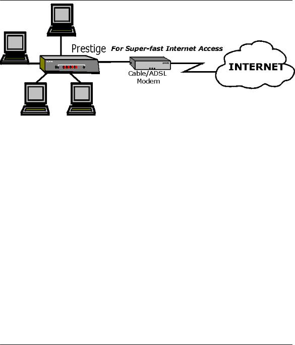
1.3Broadband Internet Access via Cable or DSL Modem
A cable modem or DSL modem can be connected to the Prestige 10M WAN Ethernet port and up to four computers can be connected to the four Prestige 10/100M LAN Ethernet ports for super-fast broadband Internet access. The Prestige provides not only the high speed Internet access but also a complete solution to efficiently manage data traffic on your network.
1-2 |
Getting to Know Your Prestige |
P314 Broadband Sharing Gateway with 4-Port Switch
Figure 1-1 Internet Access
Getting to Know Your Prestige |
1-3 |
P314 Broadband Sharing Gateway with 4-Port Switch
Chapter 2
Hardware Installation & Initial Setup
This chapter shows you how to connect the hardware and perform the initial setup.
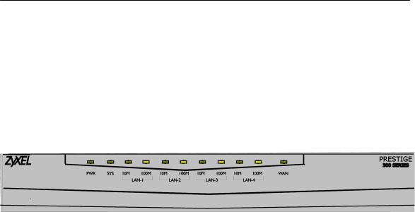
2.1Front Panel LEDs and Back Panel Ports
2.1.1 Front Panel LEDs
The LEDs on the front panel indicate the operational status of the Prestige.
|
|
|
Figure 2-1 |
Front Panel |
||
The following table describes the LED functions: |
|
|
||||
|
|
|
Table 2-1 |
LED Functions |
||
|
|
|
|
|
|
|
|
LEDs |
Function |
Indicator |
Active |
Description |
|
|
|
|
Status |
|
|
|
|
|
|
|
|
|
|
|
PWR |
Power |
Green |
On |
The power adapter is connected to the Prestige. |
|
|
|
|
|
|
|
|
|
SYS |
System |
|
Off |
The system is not ready or failed. |
|
|
|
|
|
|
|
|
|
|
|
|
On |
The system is ready and running. |
|
|
|
|
|
|
|
|
|
|
|
|
Flashing |
The system is rebooting. |
|
|
|
|
|
|
|
|
|
10M LAN |
LAN |
Green |
Off |
The 10M LAN is not connected. |
|
|
|
|
|
|
|
|
|
|
|
|
On |
The Prestige is connected to a 10M LAN. |
|
|
|
|
|
|
|
|
|
|
|
|
Flashing |
The 10M LAN is sending/receiving packets. |
|
|
|
|
|
|
|
|
|
100M LAN |
|
Orange |
Off |
The 100M LAN is not connected. |
|
|
|
|
|
|
|
|
|
|
|
|
On |
The Prestige is connected to a 100 Mbps LAN. |
|
|
|
|
|
|
|
|
|
|
|
|
Flashing |
The 100M LAN is sending/receiving packets. |
|
|
|
|
|
|
|
|
|
WAN |
WAN |
Green |
Off |
The WAN Link is not ready, or has failed. |
|
|
|
|
|
|
|
|
|
|
|
|
|
|
|
Hardware Installation and Setup |
|
2-1 |
||||
P314 Broadband Sharing Gateway with 4-Port Switch
LEDs |
Function |
Indicator |
Active |
Description |
|
|
Status |
|
|
|
|
|
|
|
|
|
|
On |
The WAN Link is ok. |
|
|
|
|
|
|
|
|
Flashing |
The 10M WAN link is sending/receiving packets. |
|
|
|
|
|
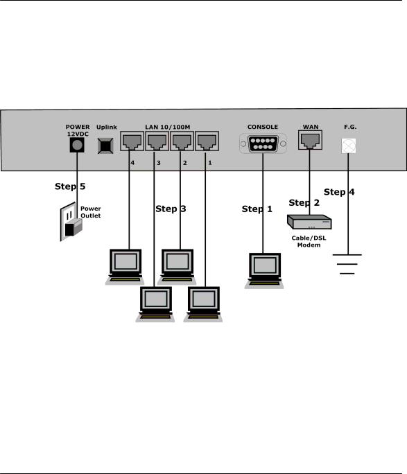
2.2Prestige 314 Rear Panel and Connections
The following figure shows the rear panel of your Prestige 314 and the connection diagram.
Figure 2-2 Prestige Rear Panel and Connections
This section outlines how to connect your Prestige 314 to the LAN and the WAN. In the case of connecting a cable modem you must connect the coaxial cable from your cable service to the threaded coaxial cable connector on the back of the cable modem. Connect a DSL Modem to the DSL Wall Jack. Please also see the Appendices for important safety instructions on making connections to the Prestige.
Step 1: Connecting the Console Port
For the initial configuration of your Prestige, you need to use terminal emulator software on a workstation and connect it to the Prestige through the console port. Connect the 9-pin end of the console cable to the console port of the Prestige and the other end (choice of 9-pin or 25-pin, depending on your computer) end to a serial port (COM1, COM2 or other COM port) of your workstation. You can use an extension RS-232
2-2 |
Hardware Installation and Setup |

P314 Broadband Sharing Gateway with 4-Port Switch
cable if the enclosed one is too short. After the initial setup, you can modify the configuration remotely through telnet connections.
Step 2: Connecting the Prestige to the Broadband Modem
Step 2a. Connecting the Prestige to the Cable Modem
Connect the WAN port on the Prestige to the Ethernet port on the cable modem using the cable that came with your cable modem. The Ethernet port on the cable modem is sometimes labeled "PC" or "Workstation".
OR
Step 2b. Connecting the Prestige to the DSL Modem
Connect the WAN port on the Prestige to the Ethernet port on the DSL modem using the cable that came with your DSL modem.
Step 3: Connecting the Prestige to your LAN
You can connect up to four computers directly to the Prestige. For each computer, connect the 10/100M LAN port on the Prestige to the Network Adapter on the PC using a straight through Ethernet cable (white tag). If you have more than four computers, you must use an external hub. Connect LAN port 4 (next to the Uplink button) on the Prestige to a port on the external hub using a straight through Ethernet cable (white tag) and press the Uplink button. If you do not press the Uplink button (LAN port 4) or use LAN ports 1 to 3 to daisy chain the Prestige to an external hub, then you must use a crossover cable (red tag).
Step 4: Grounding the Prestige
If you want to ground the Prestige then connect a grounded wire to the F.G. (Frame Ground) of the Prestige.
Step 5: Connecting the Power Adapter to your Prestige
Connect the power adapter to the port labeled POWER on the rear panel of your Prestige.
Caution: To prevent damage to the Prestige, first make sure you have the correct AC power adapter. Please see the Appendices for AC power adapter specifications for your region.
2.3Additional Installation Requirements
In addition to the contents of your package, there are other hardware and software requirements you need before you can install and use your Prestige. These requirements include:
1.A computer with an Ethernet NIC (Network Interface Card) installed.
2.A computer equipped with communications software configured to the following parameters:
♦VT100 terminal emulation.
♦9600 Baud.
♦No parity, 8 Data bits, 1 Stop bit, Flow Control set to None.
3.A cable/DSL modem and an ISP account.
After the Prestige is properly set up, you can make future changes to the configuration through telnet connections.
Hardware Installation and Setup |
2-3 |

P314 Broadband Sharing Gateway with 4-Port Switch
2.4Power Up Your Prestige
At this point, you should have connected the console port, the LAN port, the WAN port and the power port to the appropriate devices or lines. Plug the power adapter into a wall outlet. The Power LED should be on. The SYS LED will come on after the system tests are complete. The WAN LED and one of the LAN LEDs come on immediately after the SYS LED comes on, if connections have been made to the LAN and WAN ports.
Initial Screen
When you power on your Prestige, it performs several internal tests as well as line initialization. After the tests, the Prestige asks you to press [Enter] to continue, as shown.
Copyright (c) 1994 - 2000 ZyXEL Communications Corp. initialize ch =0, ethernet address: 00:a0:c5:41:51:61 initialize ch =1, ethernet address: 00:a0:c5:41:51:62 Press ENTER to continue...
Figure 2-3 |
Initial Screen |
Entering Password
The login screen appears after you press [Enter], prompting you to enter the password, as shown below. For your first login, enter the default password 1234. As you type the password, the screen displays an (X) for each character you type.
Please note that if there is no activity for longer than 5 minutes after you log in, your Prestige will automatically log you out and will display a blank screen. If you see a blank screen, press [Enter] to bring up the login screen again.
Enter Password : XXXX
Figure 2-4 Password Screen
2.5Navigating the SMT Interface
The SMT (System Management Terminal) is the interface that you use to configure your Prestige.
Several operations that you should be familiar with before you attempt to modify the configuration are listed in the table below.
2-4 |
Hardware Installation and Setup |
 Loading...