


VES-1624FT-55A
24-port VDSL2 remote IP DSLAM
User’s Guide
Version 3.53
9/2008
Edition 1
DEFAULT LOGIN
IP Address http://192.168.0.1 (Out-of-band MGMT port)
http://192.168.1.1 (In-band ports)
User Name admin
Password 1234
www.zyxel.com


About This User's Guide
About This User's Guide
Intended Audience
This manual is intended for people who want to configure the IP DSLAM using the web
configurator. You should have at least a basic knowledge of TCP/IP networking concepts and
topology.
Related Documentation
" It is recommended you use the web configurator to configure the IP DSLAM.
• Supporting Disc
Refer to the included CD for support documents.
• ZyXEL Web Site
Please refer to www.zyxel.com
certifications.
for additional support documentation and product
User Guide Feedback
Help us help you. Send all User Guide-related comments, questions or suggestions for
improvement to the following address, or use e-mail instead. Thank you!
The Technical Writing Team,
ZyXEL Communications Corp.,
6 Innovation Road II,
Science-Based Industrial Park,
Hsinchu, 300, Taiwan.
E-mail: techwriters@zyxel.com.tw
VES-1624FT-55A User’s Guide
3

Document Conventions
Document Conventions
Warnings and Notes
These are how warnings and notes are shown in this User’s Guide.
1 Warnings tell you about things that could harm you or your IP DSLAM.
" Notes tell you other important information (for example, other things you may
need to configure or helpful tips) or recommendations.
Syntax Conventions
• The VES-1624FT-55A may be referred to as the “IP DSLAM”, the “device”, the “system”
or the “product” in this User’s Guide.
• Product labels, screen names, field labels and field choices are all in bold font.
• A key stroke is denoted by square brackets and uppercase text, for example, [ENTER]
means the “enter” or “return” key on your keyboard.
• “Enter” means for you to type one or more characters and then press the [ENTER] key.
“Select” or “choose” means for you to use one of the predefined choices.
• A right angle bracket ( > ) within a screen name denotes a mouse click. For example,
Maintenance > Log > Log Setting means you first click Maintenance in the navigation
panel, then the Log sub menu and finally the Log Setting tab to get to that screen.
• Units of measurement may denote the “metric” value or the “scientific” value. For
example, “k” for kilo may denote “1000” or “1024”, “M” for mega may denote “1000000”
or “1048576” and so on.
• “e.g.,” is a shorthand for “for instance”, and “i.e.,” means “that is” or “in other words”.
4
VES-1624FT-55A User’s Guide
Document Conventions
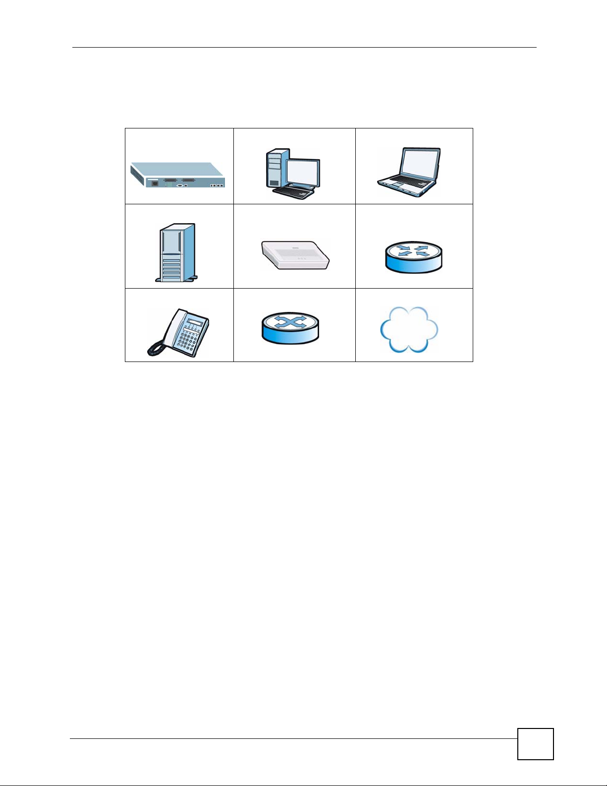
Icons Used in Figures
Figures in this User’s Guide may use the following generic icons. The IP DSLAM icon is not
an exact representation of your IP DSLAM.
IP DSLAM Computer Notebook computer
Server VDSL CPE Router
Telephone Switch Internet / Network
VES-1624FT-55A User’s Guide
5

Safety Warnings
Safety Warnings
1 For your safety, be sure to read and follow all warning notices and instructions.
• Do NOT use this product near water, for example, in a wet basement or near a swimming
pool.
• Do NOT expose your device to dampness, dust or corrosive liquids.
• Do NOT store things on the device.
• Do NOT install, use, or service this device during a thunderstorm. There is a remote risk
of electric shock from lightning.
• Connect ONLY suitable accessories to the device.
• ONLY qualified service pe rsonnel should service or disassemble this device.
• Make sure to connect the cables to the correct ports.
• Place connecting cables carefully so that no one will step on them or stumble over them.
• Always disconnect all cables from this device before servicing or disassembling.
• Use ONLY power wires of the appropriate wire gauge (see Chapter 54 on page 283 for
details) for your device. Connect it to a power supply of the correct voltage (see Chapter
54 on page 283 for details). .
• Do NOT allow anything to rest on the power adaptor or cord and do NOT place the
product where anyone can walk on the power adaptor or cord.
• Do NOT use the device if the power adaptor or cord is damaged as it might cause
electrocution.
• If the power adaptor or cord is damaged, remove it from the device and the power source.
• Do NOT attempt to repair the power adaptor or cord. Contact your local vendor to order a
new one.
• Do not use the device outside, and make sure all the connections are indoors. There is a
remote risk of electric shock from lightning.
• Caution: Risk of explosion if battery (on the motherboard) is replaced by an incorrect
type. Dispose of used batteries according to the instructions. Dispose them at the
applicable collection point for the recycling of electrical and electronic equipment. For
detailed information about recycling of this product, please contact your local city office,
your household waste disposal service or the store where you purchased the product.
• Do NOT obstruct the device ventilation slots, as insufficient airflow may harm your
device.
• Ensure that the fan filter is in place before switching on the IP DSLAM.
• Use only No. 26 AWG (American Wire Gauge) or larger telecommunication line cord.
• Fuse Warning! Replace a fuse only with a fuse of the same type and rating.
• The length of exposed (bare) power wire should not exceed 7mm.
• Fan Module Warning! Use the fan module handle when pulling out or pushing in the fan
module. Be careful not to put fingers or objects inside the fan module.
6
VES-1624FT-55A User’s Guide

Safety Warnings
• The intra-building port(s) of the equipment or subassembly is suitable for connection to
intrabuilding or unexposed wiring or cabling only. The intra-building port(s) of the
equipment or subassembly MUST NOT be metallically connected to interfaces that
connect to the OSP or its wiring. These interfaces are designed for use as intra-building
interfaces only (Type 2 or Type 4 ports as described in GR-1089-CORE, Issue 4) and
require isolation from the exposed OSP cabling. The addition of Primary Protectors is not
sufficient protection in order to connect these interfaces metallically to OSP wiring.
The intra-building port(s) of the equipment is suitable for connection only to shielded
intra-building cabling grounded at both ends.
Your product is marked with this symbol, which is known as the WEEE mark. WEEE stands
for Waste Electronics and Electrical Equipment. It means that used electrical and electronic
products should not be mixed with general waste. Used electrical and electronic equipment
should be treated separately.
VES-1624FT-55A User’s Guide
7

Safety Warnings
8
VES-1624FT-55A User’s Guide

Contents Overview
Contents Overview
Introduction ............................................................................................................................31
Introducing the IP DSLAM ......................................................................................................... 33
Hardware Installation .......................................... .......................................................... .............41
Front Panel Connections ........................................................................................................... 47
MDF Connections ......................................................................................................................53
Power Connections ...................................................................................................................55
Fan Maintenance .......................................................................................................................57
Basic Settings ........................................................................................................................59
Introducing the Web Configurator .............................................................................................. 61
Initial Configuration ....................................................................................................................69
Home and Port Statistics Screens .............................................................................................73
System Information ......... .... ... .......................................................... ... ... .... ... ... ... .... ... ... .............81
General Setup ............................................. .... ... ... ... .... ... ... ... .... ................................................ 85
User Account ............ ... ... ........................................................... ... ... ... ... .... ................................ 87
Switch Setup ............. ... ... .... ... .......................................................... ... ... .... ... .............................91
IP Setup ....................................... .... ... ... ... ... .... .......................................................... ................ 95
ENET Port Setup ....................................................................................................................... 97
xDSL Port Setup ........................................................................................................................99
xDSL Profiles Setup .................................................................................................................117
xDSL Line Data .......................................................................................................................125
Advanced Application .........................................................................................................131
VLAN ....................................................................................................................................... 133
Protocol VLAN ......................................................................................................................... 139
IGMP ....................................................................................................................................... 141
Static Multicast .........................................................................................................................151
Multicast VLAN ........................................................................................................................ 153
Packet Filtering ........................................................................................................................157
MAC Filter ................................................................................................................................ 159
Rapid Spanning Tree Protocol ................................................................................................. 161
Port Authentication ................... ... .... ... .......................................................... ... ... .... ... ... ... ........167
Port Security .......... ... ... ... ........................................................... ... ... ... ... .... .............................. 171
DHCP Relay ............................................................................................................................ 173
DHCP Snoop ........................................................................................................................... 177
2684 Routed Mode ................... ... .... ... ... ... ... .... ... ... ... .... ... ........................................................ 181
PPPoA to PPPoE .................................................................................................................... 189
VES-1624FT-55A User’s Guide
9

Contents Overview
DSCP .............................. .................... ................... .................... ................... ........................... 195
TLS PVC ................... ... .......................................................... .... ... ... ... ..................................... 197
Double Tagging (DT) ............................................................................................................... 203
ACL ..................................... ................... ................... .................... ................... ........................ 207
Downstream Broadcast ...........................................................................................................213
Upstream Broadcast .................................... .... ... ... ... .... ... ... ... .... ... ........................................... 215
Syslog ....................................... .................................................... ........................................... 217
Access Control ........................................................................................................................219
PPPoE Intermediate Agent ...................................................................................................... 225
MTU Size ................................................................................................................................. 229
OUI Filter ................................................................................................................................. 231
N1MAC .................................................................................................................................... 233
Dot3ad ..................................................................................................................................... 237
MAC Force Forwarding ...........................................................................................................241
Routing Protocol, Alarm and Management .......................................................................247
Static Routing .......................................................................................................................... 249
Alarm ....................................................................................................................................... 251
Maintenance ............................................................................................................................259
Diagnostics .............................................................................................................................. 263
MAC Table ............................................................................................................................... 269
ARP Table ........................................ ... ... ... ... .... .......................................................... ..............271
Troubleshooting and Specifications ..................................................................................273
Troubleshooting ..................................................... .................................................................. 275
Product Specifications ............................................................................................................. 283
Appendices and Index .........................................................................................................289
10
VES-1624FT-55A User’s Guide

Table of Contents
Table of Contents
About This User's Guide..........................................................................................................3
Document Conventions............................................................................................................4
Safety Warnings ........................................................................................................................6
Contents Overview ...................................................................................................................9
Table of Contents....................................................................................................................11
List of Figures.........................................................................................................................23
List of Tables...........................................................................................................................27
Part I: Introduction................................................................................. 31
Chapter 1
Introducing the IP DSLAM......................................................................................................33
1.1 Overview ............. .......................................................... ... .... ... ... .......................................... 33
1.2 Applications .............. .... ... ... ... .... ... ... ... .......................................................... .... ... ... .............33
1.2.1 MTU Application .................................................. ... .... ... ... ... ... .... ... ... ... .......................33
1.2.2 Curbside Application .................................................................................................. 34
1.3 Hardware Features ....................................................................................................... ....... 35
1.4 Software Features ................. .... .......................................................... ... ... ... .... ... ... ... ... ....... 36
Chapter 2
Hardware Installation..............................................................................................................41
2.1 General Installation Instructions ......... .............................................................. ... ................41
2.2 Dust Filter Installation ..........................................................................................................41
2.3 Installation Scenarios ............................................. ... ... ... .... ... ... ... ... .... ... ... .......................... 42
2.3.1 Desktop Installation Procedure ..................................................................................42
2.3.2 Rack-Mounted Installation ..........................................................................................43
Chapter 3
Front Panel Connections .......................................................................................................47
3.1 Front Panel ............ ... .... .......................................................... ... ... ... .... ... ............................. 47
3.1.1 Front Panel Ports ............................. .......................................................... ... ... ... .... ... 47
3.1.2 Front Panel LEDs ................................................... .... ... ... ... ... .... ... ... ... .... ...................48
3.2 1000/100M Auto-Sensing Ethernet .............................................. ... .... ... ... ... .... ... ... ... ... .......48
VES-1624FT-55A User’s Guide
11

Table of Contents
3.2.1 Ethernet Default Settings .................... ... .......................................................... ... .... ... 49
3.3 SFP Mini GBIC Slots ........................................................................... ... ... ... .... ... ... ... ... ....... 49
3.3.1 Transceiver Installation ............................................................................................. 49
3.3.2 Transceiver Removal .................................................................................................50
3.4 Console Port Connection ..................................................................................................... 51
3.5 ALARM Connection ...... ... ... ... .... ... ... ... ... ........................................................... ... ... ... ... ....... 51
3.6 VDSL Connections ....................... ... ... ... .............................................................. ... ... ..........52
Chapter 4
MDF Connections ...................................................................................................................53
4.1 MDF Connections Overview ............................... .... ... ... ....................................................... 53
4.2 MDF (Main Distribution Frame) ............. .... ..........................................................................53
4.3 Te lco-50 Cables ........ .... ... .......................................................... ... ... .... ................................ 54
Chapter 5
Power Connections ................................................................................................................55
5.1 Power Connections Overview .............................................................................................55
5.2 Power Connections ............................................ .... ... ... ... .... ... ... ... ... .... ... ... ... .......................55
Chapter 6
Fan Maintenance.....................................................................................................................57
6.1 Fan Maintenance Introduction ............................................................................................. 57
6.2 Removing and Installing the Fan Module ............................................................................ 57
Part II: Basic Settings............................................................................ 59
Chapter 7
Introducing the Web Configurator ........................................................................................61
7.1 Web Configurator Overview .................................................................................................61
7.2 Screen Privilege Levels ...... ... .... .......................................................... ... ... ... .... ... ... ... ... ....... 61
7.3 Accessing the Web Configurator .........................................................................................61
7.4 Navigation Panel ................................................................................................................. 63
7.5 Changing Your Password ....................................... ... ... ... .... ... ............................................. 66
7.6 Saving Your Configuration ...................................................................................................67
7.7 Logging Out of the Web Configurator ..................................... ............................................. 67
Chapter 8
Initial Configuration................................................................................................................69
12
8.1 Initial Configuration Overview .......................... .......................................................... ... .... ... 69
8.2 Initial Configuration .................................... ... ... ... .... .............................................................69
VES-1624FT-55A User’s Guide

Table of Contents
Chapter 9
Home and Port Statistics Screens.........................................................................................73
9.1 Home Screen ................ .......................................................... ... ... ... .... ................................ 73
9.1.1 Ethernet Port Statistics Screen ..................... ... ... ... .... ... ... ... ... .... ... ... ... .... ...................74
9.1.2 VDSL Port Statistics Screen ....................................................................................... 77
Chapter 10
System Information ................................................................................................................81
Chapter 11
General Setup..........................................................................................................................85
Chapter 12
User Account...........................................................................................................................87
12.1 User Account Screen ......................................................................................................... 87
12.2 Authentication Screen .......................................................................................................88
Chapter 13
Switch Setup ...........................................................................................................................91
13.1 Switch Modes .................................................................................................................... 91
13.1.1 Daisychain Switch Mode .......................................................................................... 91
13.1.2 Port Isolation with Daisychain Switch Mode Example .............................................. 91
13.2 Switch Setup Screen ......................................................................................................... 92
Chapter 14
IP Setup....................................................................................................................................95
Chapter 15
ENET Port Setup.....................................................................................................................97
Chapter 16
xDSL Port Setup......................................................................................................................99
16.1 DSL Profiles ....................................................................................................................... 99
16.2 Alarm Profiles .................................................................................................................... 99
16.3 Interleave Delay ................................................................................................................. 99
16.3.1 Fast Mode .............................................................................................................. 100
16.4 VDSL Parameters ............................................................................................................ 100
16.4.1 PSD ........................................................................................................................100
16.4.2 Limit PSD Mask ...................................................................................................... 100
16.4.3 RFI (Radio Frequency Interference) ......................................................................100
16.4.4 Frequency Band Plan .............................................................................................100
16.4.5 VDSL2 Profiles ....................................................................................................... 101
16.4.6 Impulse Noise Protection (INP) .............................................................................. 102
16.4.7 UPBO ..................................................................................................................... 102
16.4.8 DPBO ..................................................................................................................... 102
VES-1624FT-55A User’s Guide
13

Table of Contents
16.4.9 DPBO Electrical Length ......................................................................................... 103
16.5 DSL Standards Overview ................................................................................................ 104
16.6 Downstream and Upstream .............................................................................................104
16.7 Configured Versus Actual Rate ....................................................................................... 104
16.8 Default Settings ............................................................................................................... 104
16.9 xDSL Port Setup Screen .................................................................................................105
16.9.1 xDSL Port Setting Screen ...................................................................................... 106
16.9.2 DPBO EPSD: Custom .............................................................................................111
16.10 Virtual Channels .............................................................................................................112
16.10.1 Super Channel ......................................................................................................112
16.10.2 LLC ........................................................................................................................113
16.10.3 VC Mux .................................................................................................................113
16.11 VC Setup Screen ............................................................................................................113
Chapter 17
xDSL Profiles Setup..............................................................................................................117
17.1 xDSL Port Profile Screen ..................... ....................... ....................... ...................... .........117
17.2 IPQoS Overview ...............................................................................................................119
17.2.1 IPQoS Profile Screen ............................................................................................. 120
17.3 Alarm Profile Screen ........................................................................................................ 121
Chapter 18
xDSL Line Data......................................................................................................................125
18.1 xDSL Line Rate Info Screen ............................................................................................125
18.2 xDSL Line Data Screen ................................................................................................... 126
18.3 xDSL Performance Screen ..............................................................................................127
18.4 xDSL Statistics Screen ....................................................................................................129
Part III: Advanced Application............................................................ 131
Chapter 19
VLAN......................................................................................................................................133
19.1 Introduction to VLANs ...................................................................................................... 133
19.2 Introduction to IEEE 802.1Q Tagged VLAN ..................................................................... 133
19.2.1 Forwarding Tagged and Untagged Frames .................................... ... .... ... ... ... ... .... . 134
19.3 VLAN Status Screen ........................................................................................................134
19.4 Static VLAN Setting Screen ........................................................ ..................................... 136
19.5 VLAN Port Setting Screen ............. ... ... .... ... ............................................................. ... .... . 137
Chapter 20
Protocol VLAN.......................................................................................................................139
14
VES-1624FT-55A User’s Guide

Table of Contents
20.1 Protocol-based VLAN ...................................................................................................... 139
20.1.1 The Protocol VLAN Screen ......................... ........................................................... 139
Chapter 21
IGMP.......................................................................................................................................141
21.1 IGMP ............................................................................................................................... 141
21.2 IP Multicast Addresses ....................................................................................................141
21.2.1 IGMP Snooping ...................................................................................................... 141
21.2.2 IGMP Proxy ............................................................................................................142
21.3 IGMP Status Screen ........................................................................................................142
21.4 IGMP Bandwidth Screen ................................................................................................. 143
21.5 Bandwidth Port Setup Screen .........................................................................................145
21.6 Config Screen ..................................................................................................................146
21.7 IGMP Filter Profile Screen .......................... ....................................................... ..............147
21.8 IGMP Port Group Screen ................................................................................................148
21.9 IGMP Port Info Screen ....................................................................................................149
21.10 IGMP Count Screen ......................................................................................................149
Chapter 22
Static Multicast......................................................................................................................151
22.1 Static Multicast .................................................................................................................151
22.2 Static Multicast Screen ....................................................................................................151
Chapter 23
Multicast VLAN......................................................................................................................153
23.1 Multicast VLAN Overview ................................................................................................ 153
23.2 MVLAN Status Screen ..................................................................................................... 153
23.3 MVLAN Setup Screen .....................................................................................................154
23.4 MVLAN Group Screen .....................................................................................................155
Chapter 24
Packet Filtering.....................................................................................................................157
24.1 Packet Filter Screen ........................................................................................................157
Chapter 25
MAC Filter..............................................................................................................................159
25.1 MAC Filter Introduction ....................................................................................................159
25.2 MAC Filter Screen ...........................................................................................................159
Chapter 26
Rapid Spanning Tree Protocol.............................................................................................161
26.1 RSTP and STP ................................................................................................................ 161
26.2 RSTP Status Screen ........................................................................................................163
VES-1624FT-55A User’s Guide
15

Table of Contents
26.3 RSTP Config Screen ....................................................................................................... 164
Chapter 27
Port Authentication...............................................................................................................167
27.1 Introduction to Authentication .......................................................................................... 167
27.1.1 RADIUS ..................................................................................................................167
27.1.2 Introduction to Local User Database ...................................................................... 167
27.2 RADIUS Screen ............................................................................................................... 168
27.3 802.1x Screen .................................................................................................................169
Chapter 28
Port Security..........................................................................................................................171
28.1 Port Security Overview ....................................................................................................171
28.2 Port Security Screen ................................ ...................... ....................... ...................... ..... 171
Chapter 29
DHCP Relay...........................................................................................................................173
29.1 DHCP Relay .................................................................................................................... 173
29.2 DHCP Relay Agent Information Option (Option 82) ........................................................ 173
29.2.1 TR-101 Format ....................................................................................................... 173
29.2.2 Private Format ........................................................................................................174
29.3 DHCP Relay Screen ......................................... .... ... ... ... .... ... ... ... ... .... ..............................174
Chapter 30
DHCP Snoop..........................................................................................................................177
30.1 DHCP Snoop Overview ...................................................................................................177
30.2 DHCP Snoop Screen ....................................................................................................... 177
30.3 DHCP Snoop Status Screen ............................................................................................178
30.4 DHCP Counter Screen .................................................................................................... 179
Chapter 31
2684 Routed Mode................................................................................................................181
31.1 2684 Routed Mode ..........................................................................................................181
31.1.1 2684 Routed Mode Example ............................. ............. ............. ............. ............. . 181
31.2 2684 Routed PVC Screen ............................................................................................... 182
31.3 2684 Routed Domain Screen ..........................................................................................184
31.4 RPVC Arp Proxy Screen ................................................................................................. 185
31.5 2684 Routed Gateway Screen ........................................................................................186
Chapter 32
PPPoA to PPPoE...................................................................................................................189
32.1 PPPoA to PPPoE Overview ............................................................................................ 1 89
32.2 PPPoA to PPPoE Screen ................................................................................................ 189
16
VES-1624FT-55A User’s Guide

Table of Contents
32.3 PPPoA to PPPoE Status Screen .....................................................................................191
Chapter 33
DSCP......................................................................................................................................195
33.1 DSCP Overview ............................................................................................................... 195
33.2 DSCP Setup Screen ........................................................................................................195
33.3 DSCP Map Screen .......................................................................................................... 196
Chapter 34
TLS PVC .................................................................................................................................197
34.1 Transparent LAN Service (TLS) Overview ......................................................................197
34.1.1 TLS Network Example ........................................................................................... 197
34.2 TLS Screen ...................................................................................................................... 198
34.3 TLS PVC Screen .............................................................................................................199
Chapter 35
Double Tagging (DT).............................................................................................................203
35.1 Double Tagging Overview ................................................................................................203
35.2 Configuring DT ................................................................................................................203
35.3 Configuring DT PVC ........................................................................................................205
Chapter 36
ACL.........................................................................................................................................207
36.1 Access Control Logic (ACL) Overview ............................................................................ 207
36.1.1 ACL Profile Rules ...................................................................................................207
36.1.2 ACL Profile Actions ................................................................................................ 208
36.2 ACL Setup Screen ...........................................................................................................208
36.3 ACL Profile Screen .......................................................................................................... 210
36.4 ACL Profile Map Screen ..................................................................................................212
Chapter 37
Downstream Broadcast........................................................................................................213
37.1 Downstream Broadcast ................................................................................................... 213
37.2 Downstream Broadcast Screen .......................................................................................213
Chapter 38
Upstream Broadcast.............................................................................................................215
38.1 Upstream Broadcast Screen ............................................................................................215
Chapter 39
Syslog....................................................................................................................................217
39.1 Syslog .............................................................................................................................. 217
39.2 SysLog Screen ................................................................................................................ 217
VES-1624FT-55A User’s Guide
17

Table of Contents
Chapter 40
Access Control......................................................................................................................219
40.1 Access Control Screen ............ ... ... ... ... .... ............................................................. ... ........219
40.2 Access Control Overview ................................................................................................ 219
40.3 SNMP .............................................................................................................................. 219
40.3.1 Supported MIBs ..................................................................................................... 221
40.3.2 SNMP Traps ........................................................................................................... 221
40.4 SNMP Screen ..................................................................................................................222
40.5 Service Access Control Screen ....................................................................................... 223
40.6 Remote Management Screen .......................................................................................... 224
Chapter 41
PPPoE Intermediate Agent...................................................................................................225
41.1 PPPoE Intermediate Agent Tag Format .......................................................................... 225
41.2 PPPoE Intermediate Agent Screen .................................................................................226
Chapter 42
MTU Size................................................................................................................................229
42.1 MTU Size Screen ............................................................................................................229
Chapter 43
OUI Filter................................................................................................................................231
43.1 The OUI Filter Screen ...................................................................................................... 231
Chapter 44
N1MAC...................................................................................................................................233
44.1 Overview .......................................................................................................................... 233
44.2 N1MAC Screen ................................................................................................................ 233
44.3 N1MAC Status Screen .....................................................................................................234
Chapter 45
Dot3ad ....................................................................................................................................237
45.1 Aggregation Switch Mode ................................................................................................ 237
45.2 Dynamic Link Aggregation ............................................................................................... 237
45.2.1 Link Aggregation ID ............................................................................................... 238
45.3 Static Aggregation Example ............................................................................................ 238
45.4 Dot3ad Screen ................................................................................................................. 238
45.5 Dot3ad Status Screen ......................................................................................................239
Chapter 46
MAC Force Forwarding ........................................................................................................241
46.1 Overview .......................................................................................................................... 241
46.2 MAC Force Forwarding Examples ................................................................................... 242
18
VES-1624FT-55A User’s Guide

Table of Contents
46.3 MACFF Screen ................................................................................................................243
46.4 MACFF ARP Proxy Screen ............................................................................................. 245
Part IV: Routing Protocol, Alarm and Management.......................... 247
Chapter 47
Static Routing........................................................................................................................249
Chapter 48
Alarm......................................................................................................................................251
48.1 Alarm ............................................................................................................................... 251
48.2 Alarm Status Screen ................... ... ... ... .... ............................................................. ... ... ..... 251
48.3 Alarm Descriptions ..........................................................................................................252
48.4 Alarm History Screen ....................................................................................................... 253
48.5 Alarm Event Setup Screen .............................................................................................. 254
48.5.1 Edit Alarm Event Setup Screen ..............................................................................256
48.6 Alarm Port Setup Screen ................................................................................................. 256
Chapter 49
Maintenance..........................................................................................................................259
49.1 Maintenance Screen ........................................................................................................259
49.2 Firmware Upgrade Screen ............................................ .... ... ... ... ... .... ... ... ... .... ... ... ...........259
49.3 Restore Configuration Screen ......................................................................................... 260
49.4 Backing Up a Configuration File ...................................................................................... 260
49.5 Load Factory Defaults .....................................................................................................261
49.6 Reboot System ................................................................................................................ 261
49.7 Command Line FTP ........................................................................................................ 262
Chapter 50
Diagnostics............................................................................................................................263
50.1 Diagnostics Screen .......................................................................................................... 263
50.2 Log Format ...................................................................................................................... 265
50.2.1 Log Messages ........................................................................................................ 265
50.3 LDM Test Parameters ...................................................................................................... 266
50.4 ToneDiag Parameters ...................................................................................................... 267
Chapter 51
MAC Table..............................................................................................................................269
51.1 Introduction to MAC Table ...............................................................................................269
51.2 MAC Table Screen ...........................................................................................................270
Chapter 52
ARP Table..............................................................................................................................271
VES-1624FT-55A User’s Guide
19

Table of Contents
52.1 Introduction to ARP Table ................................................................................................ 271
52.1.1 How ARP Works ......................................................... ... ... ... .... ... ... ........................ 271
52.2 ARP Table Screen ...........................................................................................................271
Part V: Troubleshooting and Specifications...................................... 273
Chapter 53
Troubleshooting....................................................................................................................275
53.1 The SYS or PWR LED Does Not Turn On ....................................................................... 275
53.2 The ALM LED Is On ........................................................................................................ 275
53.3 SFP LNK LEDs Do Not Turn On ...................................................................................... 276
53.4 100/1000 LEDs Do Not Turn On ...................................................................................... 276
53.5 100/1000 Ethernet Port Data Transmission ................................................ ..................... 276
53.6 DSL Data Transmission ................................................................................................... 277
53.7 There Is No Voice on an VDSL Connection ................................................... ... ... ... ... .... . 277
53.8 Local Server ....................................................................................................................278
53.9 Data Rate ........................................................................................................................278
53.10 Configured Settings .......................................................................................................278
53.11 Password ..................................... ... .......................................................... .... ... ... ... ........ 278
53.12 System Lockout ............................................................................................................. 279
53.13 SNMP ............................................................................................................................ 279
53.14 Telnet ............................................................................................................................. 279
53.15 Resetting the Defaults ...................................................................................................280
53.15.1 Resetting the Defaults Via Command .................................................................. 280
53.15.2 Uploading the Default Configuration File .............................................................281
53.16 Recovering the Firmware ..............................................................................................282
Chapter 54
Product Specifications.........................................................................................................283
54.1 Physical Specifications ....................................................................................................283
54.2 Default Settings ............................................................................................................... 285
54.3 Pin Assignments ..............................................................................................................287
54.3.1 Hardware Telco-50 Connector Pin Assignments .................................................... 287
54.3.2 Console Cable Pin Assignments ............................................................................ 287
54.4 ALARM Connector Pin Assignments ............................................................................... 288
Part VI: Appendices and Index ........................................................... 289
Appendix A Changing a Fuse ..............................................................................................291
Appendix B Legal Information ..............................................................................................293
20
VES-1624FT-55A User’s Guide

Table of Contents
Appendix C Customer Support.............................................................................................297
Index.......................................................................................................................................303
VES-1624FT-55A User’s Guide
21

Table of Contents
22
VES-1624FT-55A User’s Guide

List of Figures
List of Figures
Figure 1 MTU Application ....................................................................................................................... 34
Figure 2 Curbside Application ................................................................................................................ 35
Figure 3 Dust Filter Magnets .................................................................................................................. 41
Figure 4 Dust Filter Installation ...............................................................................................................42
Figure 5 Dust Filter Handle ..................................................................................................................... 42
Figure 6 Attaching Rubber Feet ............................................................................................................. 43
Figure 7 Attaching Mounting Brackets and Screws ................................................................................44
Figure 8 Rack Mounting .........................................................................................................................45
Figure 9 IP DSLAM Front Panel ............................................................................................................. 47
Figure 10 SFP Mini GBIC Slots .............................................................................................................. 49
Figure 11 Transceiver Installation ....................................................... .................................................... 50
Figure 12 Installed Transceiver .............................................................................................................. 50
Figure 13 Opening the Transceiver Latch ................ .... .......................................................... ... .............50
Figure 14 Removing the Transceiver ......................................... ...... ....... ...... ...... ....... ... ....... ...... ............. 51
Figure 15 ALARM Pins Layout ............................................................................................................... 51
Figure 16 MDF (Main Distribution Frame) Wiring ................................................................................... 53
Figure 17 Telco-50 Cable with RJ-11 Connectors ..................................................................................54
Figure 18 Fan Module Thumbscrews ..................................................................................................... 57
Figure 19 Removing the Fan Module ..................................................................................................... 58
Figure 20 Fan Module Removed ............................................................................................................ 58
Figure 21 Login ....................................................................................................................................... 62
Figure 22 Home ...................................................................................................................................... 62
Figure 23 User Account ...................................................... ... .... ............................................................. 66
Figure 24 User Account ...................................................... ... .... ............................................................. 66
Figure 25 Logout .................................................................................................................................... 67
Figure 26 IP Setup .................................................................................................................................. 69
Figure 27 xDSL Port Setup ..................................................................................................................... 70
Figure 28 VLAN Port Settings ................................................................................................................70
Figure 29 VLAN Port Settings ................................................................................................................71
Figure 30 VLAN Port Settings ................................................................................................................71
Figure 31 Config Save ............................................................................................................................ 71
Figure 32 Configuration Save Successfully ............................... ................................................ .............71
Figure 33 Home ...................................................................................................................................... 73
Figure 34 Port Statistics (Ethernet) .................................................................. .................... ................... 75
Figure 35 Port Statistics (VDSL) ...................... ............................................................. ... .... ...................78
Figure 36 System Info ............................................................................................................................ 81
Figure 37 General Setup .............................. ... ... ... ... .... ... ... ... ................................................................. 85
Figure 38 User Account ...................................................... ... .... ............................................................. 87
VES-1624FT-55A User’s Guide
23

List of Figures
Figure 39 Authentication ......................................................................................................................... 88
Figure 40 Port Isolation with Daisychain Switch Mode Example ............................................................ 92
Figure 41 Switch Setup ...................................................... ... .... ... ... ... .................................................... 92
Figure 42 IP Setup .................................................................................................................................. 95
Figure 43 ENET Port Setup ....................................................................................................................97
Figure 44 A Band Plan Example ..........................................................................................................101
Figure 45 UPBO Resolves Upstream Far-End Crosstalk ..................................................................... 102
Figure 46 DPBO Resolves Downstream Far-End Crosstalk . .... ... ... ... .... ... ... ... ... .... .............................. 103
Figure 47 xDSL Port Setup ................................................................................................................... 105
Figure 48 Select Ports .......................................................................................................................... 105
Figure 49 xDSL Port Setting .................................................................................................................107
Figure 50 Optionmask options ..............................................................................................................109
Figure 51 DPBO EPSD: Custom ..........................................................................................................111
Figure 52 VC Setup ...............................................................................................................................113
Figure 53 Basic Setting > xDSL Port Setup > VC Setup > Delete ................... ... .... ...............................115
Figure 54 Select Ports ...........................................................................................................................115
Figure 55 Select Ports ...........................................................................................................................116
Figure 56 Port Profile ............................. ... .... ... ... ... ... .... .........................................................................117
Figure 57 IPQoS Profile ........................................................................................................................ 120
Figure 58 Alarm Profile .........................................................................................................................122
Figure 59 xDSL Line Rate Info .............................................................................................................125
Figure 60 xDSL Line Data .................................................................................................................... 127
Figure 61 xDSL Performance ............................................................................................................... 128
Figure 62 xDSL Statistics ..................................................................................................................... 130
Figure 63 VLAN Status ......................................................................................................................... 135
Figure 64 Static VLAN Setting ..............................................................................................................136
Figure 65 VLAN Port Setting ................................................................................................................ 137
Figure 66 Select Ports .......................................................................................................................... 138
Figure 67 Protocol VLAN ......................................................................................................................139
Figure 68 IGMP Proxy Network Example .............................................................................................142
Figure 69 IGMP (Status) ....................................................................................................................... 143
Figure 70 IGMP Bandwidth ..................................................................................................................144
Figure 71 Bandwidth Port Setup ........................................................................................................... 145
Figure 72 IGMP Config ......................................................................................................................... 146
Figure 73 IGMP Filter Profile ................................................................................................................ 147
Figure 74 IGMP Port Group .................................................................................................................. 148
Figure 75 IGMP Port Info ...................................................................................................................... 149
Figure 76 IGMP Count .......................................................................................................................... 150
Figure 77 Static Multicast ..................................................................................................................... 151
Figure 78 MVLAN Status ......................................................................................................................153
Figure 79 MVLAN Setup ....................................................................................................................... 154
Figure 80 MVLAN Group ...................................................................................................................... 156
Figure 81 Packet Filter .........................................................................................................................157
24
VES-1624FT-55A User’s Guide

List of Figures
Figure 82 MAC Filter ............................................................................................................................159
Figure 83 STP Root Ports and Designated Ports ................................................................................. 162
Figure 84 RSTP Status ......................................................................................................................... 163
Figure 85 RSTP Config ........................................................................................................................165
Figure 86 RADIUS Server .................................................................................................................... 167
Figure 87 RADIUS ................................................................................................................................ 168
Figure 88 802.1x ................................................................................................................................... 169
Figure 89 Port Security .................................................... ... ... .... ........................................................... 171
Figure 90 Select Ports .......................................................................................................................... 172
Figure 91 DHCP Relay Agent Circuit ID Sub-option Format .................................. ... ... ... .... ... ... ... ... .... . 174
Figure 92 DHCP Relay Agent Remote ID Sub-option Format ..............................................................174
Figure 93 DHCP Relay ......................................................................................................................... 175
Figure 94 DHCP Snoop ........................................................................................................................177
Figure 95 DHCP Snoop Status ............................................................................................................. 178
Figure 96 DHCP Counter .....................................................................................................................179
Figure 97 2684 Routed Mode Example ................................................................................................ 182
Figure 98 2684 Routed PVC . ... ... .... ... ... ... .... ... ... ... ... .... ... ... ... .... ... ........................................................ 183
Figure 99 2684 Routed Domain ................................................................ ... ... ... .... ... ... ... .... ... ... ...........184
Figure 100 RPVC Arp Proxy ................................................................................................................. 185
Figure 101 2684 Routed Gateway ........................................................................................................186
Figure 102 Mixed PPPoA-to-PPPoE Broadband Network Example ................................................... 189
Figure 103 PPPoA to PPPoE ...............................................................................................................190
Figure 104 PPPoA to PPPoE Status ....................................................................................................192
Figure 105 DSCP Setup ....................................................................................................................... 195
Figure 106 DSCP Map .........................................................................................................................196
Figure 107 Transparent LAN Service Network Example ..................................................................... 198
Figure 108 TLS .....................................................................................................................................198
Figure 109 TLS PVC ............................................................................................................................200
Figure 110 DT ....................................................................................................................................... 204
Figure 111 DT PVC ...............................................................................................................................205
Figure 112 ACL Setup .......................................................................................................................... 209
Figure 113 ACL Profile .........................................................................................................................210
Figure 114 ACL Profile Map .................................................................................................................212
Figure 115 Downstream Broadcast ......................................................................................................213
Figure 116 Upstream Broadcast ...........................................................................................................215
Figure 117 SysLog ................................................................................................................................ 217
Figure 118 Access Control ...................................................................................................................219
Figure 119 SNMP Management Model ................................................................................................ 220
Figure 120 SNMP ................................................................................................................................. 222
Figure 121 Service Access Control ...................................................................................................... 223
Figure 122 Remote Management (Secured Client Setup) ................................................................... 224
Figure 123 PPPoE Intermediate Agent ................................................................................................ 226
Figure 124 MTU .................................................................................................................................... 229
VES-1624FT-55A User’s Guide
25

List of Figures
Figure 125 OUI Filter ............................................................................................................................ 231
Figure 126 N1MAC ...............................................................................................................................233
Figure 127 N1MAC ...............................................................................................................................234
Figure 128 N1MAC ...............................................................................................................................234
Figure 129 Aggregation Example - Physical Connections ...................................................................238
Figure 130 Dot3ad ............................................................................................................................... 239
Figure 131 Dot3ad Status ..................................................................................................................... 239
Figure 132 MAC Force Forwarding ......................................................................................................241
Figure 133 MAC Force Forwarding Configuration Example 1 .............................................................. 242
Figure 134 MAC Force Forwarding Configuration Example 2 .............................................................. 243
Figure 135 MAC Force Forwarding Configuration Example 3 .............................................................. 243
Figure 136 MAC Force Forwarding ......................................................................................................244
Figure 137 MAC ARP Proxy .................................................................................................................246
Figure 138 Static Routing ..................................................................................................................... 249
Figure 139 Alarm Status .......................................................................................................................251
Figure 140 Alarm History ......................................................................................................................254
Figure 141 Alarm Event Setup .............................................................................................................255
Figure 142 Alarm Event Setup Edit ...................................................................................................... 256
Figure 143 Alarm Port Setup ................................................................................................................ 257
Figure 144 Maintenance .......................................................................................................................259
Figure 145 Firmware Upgrade .............................................................................................................. 259
Figure 146 Restore Configuration ........................................................................................................ 260
Figure 147 Restore Default Configuration ............................................................................................261
Figure 148 Restore Factory Default Settings, Reboot .......................................................................... 261
Figure 149 Reboot System ...................................................................................................................262
Figure 150 Diagnostic ........................................................................................................................... 263
Figure 151 MAC Table Filtering Flowchart ...........................................................................................269
Figure 152 MAC Table .......................................................................................................................... 270
Figure 153 ARP Table .......................................................................................................................... 272
Figure 154 Resetting the Switch Via Command ................................................................................... 280
Figure 155 Example Xmodem Upload ............................. ................... .................... ................... ........... 281
Figure 156 Example Xmodem Upload ............................. ................... .................... ................... ........... 282
Figure 157 CO 1-24 and USER 1-24 Telco-50 Pin Assignments ......................................................... 287
Figure 158 Console Cable RJ-11 Male Connector .................................... ........................................... 287
Figure 159 Console Cable DB-9 Female Connector ...... ... ... .... ... ... ... .... ... ... ........................................ 288
Figure 160 ALARM Connector Pin Layout ........................................................................................... 288
26
VES-1624FT-55A User’s Guide

List of Tables
List of Tables
Table 1 IP DSLAM Front Panel Ports .................................................................................................... 47
Table 2 LED Descriptions ......................................................................................................................48
Table 3 Navigation Panel Submenu Links ............................................................................................. 63
Table 4 Web Configurator Screens ........................................................................................................64
Table 5 Home ........................................................................................................................................ 73
Table 6 Port Statistics (Ethernet) ...........................................................................................................75
Table 7 Port Statistics (VDSL) ............................................................................................................... 78
Table 8 System Info ...............................................................................................................................82
Table 9 General Setup ........................................................................................................................... 85
Table 10 User Account ...................... ... ... .... ... ... ... ... .... ... ....................................................................... 87
Table 11 Authentication ......................................................................................................................... 89
Table 12 Switch Set up .......................... ... .... ... ... ... ... ..............................................................................92
Table 13 IP Setup ........................................................ ... .......................................................................95
Table 14 ENET Port Setup .................................................................................................................... 97
Table 15 Optional band PSD Mask ......................................................................................................101
Table 16 VDSL2 Profiles In The Device .............................................................................................. 101
Table 17 Real Length to Electrical Length ......................... ... ............................................................... 103
Table 18 DSL Standards Maximum Transfer Rates .............................................................................104
Table 19 xDSL Port Setup ...................................................................................................................105
Table 20 xDSL Port Setting ................................................................................................................. 108
Table 21 DPBO EPSD: Custom ............................................................................................................112
Table 22 VC Setup ................................................................................................................................114
Table 23 xDSL Port Profile ...................................................................................................................117
Table 24 IPQoS Profile ........................................................................................................................ 120
Table 25 Alarm Profile ......................................................................................................................... 122
Table 26 xDSL Line Rate Info ......................... ... ... ... .... ... ... .................................................................. 125
Table 27 xDSL Line Data ..................................................................................................................... 127
Table 28 xDSL Performance ................................................................................................................128
Table 29 xDSL Statistics ...................................................................................................................... 130
Table 30 VLAN Status .......................................................................................................................... 135
Table 31 Static VLAN Setting ............................................................................................................... 136
Table 32 VLAN Port Setting ................................................................................................................. 137
Table 33 Protocol VLAN ...................................................................................................................... 139
Table 34 IGMP (Status) .......................................................................................................................143
Table 35 IGMP Bandwidth ................................................................................................................... 144
Table 36 Bandwidth Port Setup ........................................................................................................... 145
Table 37 IGMP Config .........................................................................................................................146
Table 38 IGMP Filter Profile .................................................................................................................147
VES-1624FT-55A User’s Guide
27

List of Tables
Table 39 IGMP Port Group ..................................................................................................................148
Table 40 IGMP Port Info ...................................................................................................................... 149
Table 41 IGMP Counts ........................................................................................................................ 150
Table 42 Static Multicast ...................................................................................................................... 151
Table 43 MVLAN Status ....................................................................................................................... 154
Table 44 MVLAN Setup .......................................................................................................................155
Table 45 MVLAN Group .......................................................................................................................156
Table 46 Packet Filter .......................................................................................................................... 157
Table 47 MAC Filter ............................................................................................................................. 159
Table 48 Path Cost ...................................................... ... ... ... .... ... ... ... .... ... ........................................... 161
Table 49 RSTP Port States .................................................................................................................. 162
Table 50 RSTP Status ......................................................................................................................... 163
Table 51 RSTP Config ......................................................................................................................... 165
Table 52 RADIUS ............................................................................................................................... 168
Table 53 802.1x ...................................................................................................................................169
Table 54 Port Security .................... ... ... ... .... ... ... .......................................................... ... .....................171
Table 55 DHCP Relay Agent Circuit ID Sub-option Format: TR-101 for VDSL ................................... 174
Table 56 DHCP Relay Agent Circuit ID Sub-option Format: TR-101 for ADSL ................................... 174
Table 57 DHCP Relay ..........................................................................................................................175
Table 58 DHCP Snoop ........................................................................................................................ 178
Table 59 DHCP Snoop Status ............................................................................................................. 179
Table 60 DHCP Counter ......................................................................................................................179
Table 61 2684 Routed PVC ............................... ... ... .... ... ... ... .... ... ... ... .... ... ... ... ..................................... 183
Table 62 2684 Routed Domain ............................................................................................................184
Table 63 RPVC Arp Proxy ...................................................................................................................186
Table 64 2684 Routed Gateway ........................................................ .... ... ... ... ... .... ... ... ... .... ... ... ...........186
Table 65 PPPoA to PPPoE ..................................................................................................................190
Table 66 PPPoA to PPPoE Status ....................................................................................................... 192
Table 67 DSCP Setup .......................................................................................................................... 195
Table 68 DSCP Map ............................................................................................................................ 196
Table 69 TLS ........................ ... ... .... ... ... .......................................................... ... .... ... ... ........................199
Table 70 TLS PVC ............................. ... ... .... .......................................................... ... ... ... .....................200
Table 71 DT .........................................................................................................................................204
Table 72 DT PVC .................................................................................................................................205
Table 73 ACL Setup .............................................................................................................................209
Table 74 ACL Profile .............................................................................................................................211
Table 75 ACL Profile Map .................................................................................................................... 212
Table 76 Downstream Broadcast ................................................. ................... ................ ..................... 213
Table 77 Upstream Broadcast .................................................. ... ... ... .... ... ........................................... 215
Table 78 SysLog ............................. ... ... ... .......................................................... .... ... ... ... .....................217
Table 79 Access Control Summary ..................................................................................................... 219
Table 80 SNMP Commands ................................................................................................................220
Table 81 SNMPv2 Traps ......................................................................................................................221
28
VES-1624FT-55A User’s Guide

List of Tables
Table 82 SNMP .................................................................................................................................... 222
Table 83 Service Access Control ......................................................................................................... 223
Table 84 Remote Management (Secured Client Setup) ...................................................................... 224
Table 85 PPPoE Intermediate Agent Vendor-specific Tag Format ...................................................... 225
Table 86 PPPoE Intermediate Agent Vendor-specific Tag Format ...................................................... 225
Table 87 PPPoE Intermediate Agent Remote ID Sub-option Format .................................................. 225
Table 88 PPPoE Intermediate Agent Sub-option Format: TR-101 for VDSL ....................................... 226
Table 89 PPPoE Intermediate Agent Sub-option Format: TR-101 for ADSL ....................................... 226
Table 90 PPPoE Intermediate Agent ................................................................................................... 227
Table 91 MTU ...................................................................................................................................... 229
Table 92 OUI Filter ............................................................................................................................... 231
Table 93 N1MAC ................................................................................................................................. 234
Table 94 N1MAC ................................................................................................................................. 234
Table 95 Link Aggregation ID: Local IP DSLAM .......................... ... ... .... ... ... ... ... .... ... ... ... .... ... ... ... ... .... .238
Table 96 Link Aggregation ID: Peer IP DSLAM ...................................................................................238
Table 97 Switch Set up Dot3ad ................................................................................. ... ... .....................239
Table 98 Dot3ad Status ....................................................................................................................... 240
Table 99 MAC Force Forwarding Example: IP Address Settings ........................................................ 242
Table 100 MAC Force Forwarding ....................................................................................................... 244
Table 101 Maximum Host Numbers .................................................................................................... 245
Table 102 Alternative Subnet Mask Notation .......................................................................................245
Table 103 MAC ARP Proxy ................................................................................................................. 246
Table 104 Static Routing ......................................................................................................................249
Table 105 Alarm Status ........................................................................................................................ 252
Table 106 Alarm Descriptions .............................................................................................................. 252
Table 107 Alarm History ...................................................................................................................... 254
Table 108 Alarm Event Setup ..............................................................................................................255
Table 109 Alarm Event Setup Edit ....................................................................................................... 256
Table 110 Alarm Port Setup .................................................................................................................257
Table 111 Diagnostics .......................................................................................................................... 264
Table 112 Log Format ..........................................................................................................................265
Table 113 Log Messages .....................................................................................................................265
Table 114 LDM Test Parameters ......................................................................................................... 266
Table 115 ToneDiag Parameters ......................................................................................................... 267
Table 116 MAC Table ...........................................................................................................................270
Table 117 ARP Table ...........................................................................................................................272
Table 118 SYS LED Troubleshooting ..................................................................................................275
Table 119 ALM LED Troubleshooting .................................................................................................. 275
Table 120 SFP LNK LED Troubleshooting .......................................................................................... 276
Table 121 100/1000 LED Troubleshooting .......................................................................................... 276
Table 122 Troubleshooting Data Transmission .................................................................................... 276
Table 123 DSL Data Transmission Troubleshooting ............................................................................ 277
Table 124 VDSL Voice Troubleshooting .............................................................................................. 277
VES-1624FT-55A User’s Guide
29

List of Tables
Table 125 Troubleshooting a Local Server ..........................................................................................278
Table 126 Troubleshooting the SYNC-rate ..........................................................................................278
Table 127 Troubleshooting the IP DSLAM’s Configured Settings ....................................................... 278
Table 128 Troubleshooting the SNMP Server .....................................................................................279
Table 129 Troubleshooting Telnet ........................................................................................................ 279
Table 130 Wire Gauge Sp ecifications ..................................................................................................283
Table 131 Fuse Specifications ............................................................................................................. 284
Table 132 Default Settings ...................................................................................................................285
Table 133 Console Cable Connector Pin Assignments ....................................................................... 288
Table 134 ALARM Connector Pin Assignments .................................................................................. 288
30
VES-1624FT-55A User’s Guide

PART I
Introduction
Introducing the IP DSLAM (33)
Hardware Installation (41)
Front Panel Connections (47)
MDF Connections (53)
Power Connections (55)
Fan Maintenance (57)
31

32

CHAPTER 1
Introducing the IP DSLAM
This chapter introduces the main applications and features of the IP DSLAM. It also
introduces the ways you can manage the IP DSLAM.
1.1 Overview
This chapter describes the system features, applications and specifications of your IP DSLAM.
The IP DSLAM is an IP-based DSLAM (Internet Protocol Digital Subscriber Line Access
Multiplexer) that connects VDSL and voice subscribers to the Internet. As a high-performance
but yet compact platform, it can conveniently deliver broadband Internet access and VoIP
telephony service (over existing POTS telephone wiring) to multi-tenant units (MTUs),
hospitals, hotels, schools, university campuses and ISPs. The IP DSLAM’s low cost and easy
management make it a perfect DSL-provider solution.
The IP DSLAM platform allows for convenient management and support of VDSL
technology. Up to 24 VDSL subscribers can simultaneously utilize a wide range of powerful
broadband services.
1.2 Applications
These are the main applications for the IP DSLAM:
• Internet access, multimedia and phone services for Multiple Tenant Units (MTU).
• Other applications include telemedicine, surveillance systems, remote server systems,
cellular base stations and high-quality teleconferencing.
1.2.1 MTU Application
The following diagram depicts a typical application of the IP DSLAM with ADSL modems, in
a large residential building, or multiple tenant unit (MTU), that leverages existing phone line
wiring to provide Internet access and voice service to all tenants. Note that ADSL service can
coexist with voice service on the same line.
VES-1624FT-55A User’s Guide
33

Chapter 1 Introducing the IP DSLAM
Figure 1 MTU Application
1.2.2 Curbside Application
The IP DSLAM can also be used by an Internet Service Provider (ISP) in a street cabinet to
form a “mini POP (Point-of-Presence)” to provide broadband and phone services to residential
areas that are too far away from the ISP to avail of DSL or PSTN phone service. Residents
need an ADSL modem for data services, connected as shown in the previous figure.
34
VES-1624FT-55A User’s Guide

Figure 2 Curbside Application
Chapter 1 Introducing the IP DSLAM
1.3 Hardware Features
This section describes the ports on the IP DSLAM.
1000/100 Mbps Ethernet Ports
The IP DSLAM has two 1000/100Mbps auto-sensing Ethernet ports.
They allow you to:
• Connect the IP DSLAM to a second-level IP DSLAM
• Daisy-chain other IP DSLAM
SFP Slots
Install SFP (Small Form-factor Pluggable) transceivers in these slots to connect to other IP
DSLAMs at longer distances than the Ethernet port.
Stacking
Daisy-chain up to three IP DSLAM (or other Ethernet devices).
Integrated Splitters
The integrated DSL splitter eliminates the need to use external splitters that separate the voiceband and VDSL signals.
Console Port
Use the console port for local management of the IP DSLAM.
VES-1624FT-55A User’s Guide
35

Chapter 1 Introducing the IP DSLAM
Fans
The fans cool the IP DSLAM sufficiently to allow reliable operation of the IP DSLAM in even
poorly ventilated rooms or basements. To conserve energy and reduce noise, the fan speed
depends on the temperature.
Alarm LED
An ALM (alarm) LED lights when the IP DSLAM is overheated, the fans are not working
properly , the voltage readings are outside the tolerance levels or an alarm has been detected on
the ALARM input pins.
Outband Management Interface
The IP DSLAM has one 10/100 auto-sensing UTP (unshielded twisted pair) port for outband
Ethernet Manament.
1.4 Software Features
This section describes the general software features of the IP DSLAM.
System Monitoring
• System status (link status, rates, statistics counters)
• Temperatures, voltage reports and alarms.
DMT Modulation
The IP DSLAM, with the VDSL modem such as P-870H-51 or P-870HW-51, offers service
providers a DMT (Discrete Multi-T one)-based VDSL solution. DMT modulation allows the IP
DSLAM to dynamically adapt to the bit rate based on the line condition.
Band Plan Support
Band plan is controlled by Limit PSD Mask (refer to Section 16.4.2 on page 100). All options
of Limit PSD Mask for this IP DSLAM follow the band plan defined in G.993.2.The IP
DSLAM supports VDSL band Plan.
VDSL Profiles
Profiles allow you to configure VDSL ports efficiently. You can configure all of the VDSL
ports with the same profile, thus removing the need to configure the VDSL ports one-by-one.
You can also change an individual VDSL port by assigning it a different profile. The [Product
Name (long)]
supports the VDSL2 profiles including
• The DS1 frequency band of the 17a profile starts at 138 kHz and the edge freq uency of the
upper band of the 17a profile is 17.664 MHz.
• The VDSL2 profiles are programmable and automatically adapt according to the line
condition of each VDSL2 line.
8a, 8b, 8c, 8d, 12a, 12b and 17a.
36
VES-1624FT-55A User’s Guide

Chapter 1 Introducing the IP DSLAM
IP Protocols
• IP Host (No routing)
• Telnet for configuration and monitoring
• SNMP for management
• SNMP MIB II (RFC 1213)
• SNMP v1 RFC 1157
• SNMPv2, SNMPv2c or later version
• Bridge MIBs (RFC 1493, 2674)
• SMI RFC 1155
•Private MIBs
• RFC 3728 VDSL MIB
VDSL2 to ADSL2+ Fall Back
The IP DSLAM provides ADSL2+ fall back feature in addition to the VDSL2 PTM (Packet
Transmission Mode) service. W ith ADSL2+ fall back turned on, the IP DSLAM can de tect an
ADSL modem connected to a subscriber line. Then the IP DSLAM switches the operation
mode of the corresponding port to ADSL2+ and establishes the corresponding connection service. This helps Telco operators to provide differentiating services (ADSL service can coexist
with VDSL service on the same subscriber line) using a single DSLAM. At the time of writing, the IP DSLAM supports the following features.
• ADSL2+ fall back
• Bi-directional AAL5 ATM VCs
• PPPoA and IPoA/IPoE
• PVC to VLAN mapping
Refer to ITU-T G.992.1, G.992.3 and G. 992.5 for more information.
IEEE 802.1Q Tagged VLAN
Your management IP DSLAM card uses the IEEE 802.1Q Tagged VLAN (Virtual Local Area
Network), which allows your device to deliver tagged/untagged frames to and from its ports.
IEEE 802.1p Priority
Your IP DSLAM uses IEEE 802.1p Priority to assign priority levels to individual PVCs.
IGMP Count Limit
You can limit the number of IGMP groups a subscriber on a port can join. You may enable/
disable the IGMP count limit on individual ports.
Static Multicast
Use static multicast to allow incoming frames based on multicast MAC address(es) that you
specify. This feature can be used in conjunction with IGMP snooping and IGMP proxy to
allow multicast MAC address(es) that are not learned by IGMP snooping or IGMP proxy.
VES-1624FT-55A User’s Guide
37

Chapter 1 Introducing the IP DSLAM
Multicast VLAN
Multicast VLAN is designed for applications (such as Media-on-Demand (MoD)) using
multicast traffic across an Ethernet ring-based service provider network. Multicast VLAN
allows one single multicast VLAN to be shared among different subscriber VLANs on the
network. This improves bandwidth utilization by reducing multicast traffic in the subscriber
VLANs and simplifies multicast group management.
VLAN Isolation
Use isolation to block the VDSL2 subscribers in a specific VLAN from sending traffic directly
to each other.
MAC (Media Access Control) Filter
Use the MAC filter to accept or deny incoming frames based on MAC (Media Access Control)
address(es) that you specify. You may enable/disable the MAC filter on specific ports. You
may specify up to ten MAC addresses per port.
Security
• Password protection for system management
•VLAN
• RADIUS client
STP (Spanning Tree Protocol) / RSTP (Rapid STP)
(R)STP detects and breaks network loops and provides backup links between IP DSLAMs,
bridges or routers. It allows a IP DSLAM to interact with other (R)STP -compliant IP
DSLAMs in your network to ensure that only one path exists between any two stations on the
network.
IEEE 802.1x Port-based Authentication
The IP DSLAM supports the IEEE 802.1x standard for centralized user authentication and
accounting management through an optional netw ork authentication (RADIUS) server.
MAC (Media Access Control) Count Filter
You can limit the number of MAC addresses that may be dynamically learned on a port. You
may enable/disable the MAC count filter on individual ports.
DHCP Relay
DHCP (Dynamic Host Configuration Protocol RFC 2131 and RFC 2132) allows individual
computers to obtain TCP/IP configuration at start-up from a server. You can configure the
system as a DHCP relay agent to have another DHCP server provide TCP/IP configuration for
the clients. In addition, you can set the system to forward client DHCP requests to specific
DHCP servers based on the VLAN ID. You can also specify up to two DHCP servers for each
VLAN to provide fail-over protection.
38
VES-1624FT-55A User’s Guide

Chapter 1 Introducing the IP DSLAM
DHCP Relay Option 82
The system supports DHCP relay agent82 (RFC 3046) that adds additional information to
client DHCP requests that the IP DSLAM relays to a DHCP server. It also supports adding the
sub-option 2 (Remote ID) with additional information.
DHCP Snooping
DHCP snooping allows the system to identify packets with DHCP server assigned IP
address(es) and block access of devices using unknown IP addresses on a subscriber port. You
can also manually add static IP addresses to the DHCP snooping table.
2684 Routed Mode
The IP DSLAM can handle 2684 routed mode traffic.
PPPoA-to-PPPoE (PAE) PVC
This feature allows the system to translate PPPoA packets to PPPoE packets (and vice versa)
to allow communication between CPE clients and an access concentrator (such as a BRAS)
through the IP DSLAM.
DSCP-to-IEEE 802.1p Priority Mapping
DiffServ is a class of service (CoS) model that marks packets with DiffServ Code Points
(DSCP) so that they receive specific per-hop treatment at DiffServ-compliant network devices
along the route. You can configure DSCP-to-IEEE 802.1p mappings to allow the IP DSLAM
to prioritize all incoming traffic based on the DSCP value according to the mapping table.
Transparent LAN Service (TLS)
Use TLS (also known as VLAN stacking) to add an outer VLAN tag to the inner IEEE 802.1Q
tagged frames that enter the network. By tagging the tagged frames (“double-tagged” frames),
the service provider can manage up to 4,094 VLAN groups with each group containing up to
4,094 customer VLANs. This allows a service provider to provide different services based on
specific VLANs, for many different customers.
Downstream Broadcast
The IP DSLAM can block downstream broadcast packets from being sent to specified VLANs
on specified ports.
Upstream Broadcast Rate Limiting
Rate Limiting on the subscriber ports allows service providers to offer tiered service in
increments of 32 Kbps. This service differentiation is not only to fulfill the needs of different
customers, but also to provide a network infrastructure that combines guaranteed performance
and flexibility in service provisioning.
System Error Logging
The IP DSLAM’s system error log will record error logs locally. These logs may be viewed
again after a warm restart.
VES-1624FT-55A User’s Guide
39

Chapter 1 Introducing the IP DSLAM
Management
• Remote configuration backup/restore and firmware upgrade
•SNMP manageable
• Text-based management locally via console port and remotely via telnet
• Editable plain text based configuration file
PPPoE Intermediate Agent Information
Similar to DHCP relay option82, you can set the system to insert line information into client
PPPoE Active Discovery Initialization (PADI) packets. This allows a PPPoE termination
server to identify and authenticate a PPPoE client.
Single End Loop Test (SELT)
This feature checks the distance to an ADSL subscriber’s location.
MAC Force Forwarding
This feature forces subscriber(s) to communicate with uplink device(s) through an IPv4
gateway. The gateway then routes or forwards subscriber traffic so the subscribers do not
know the MAC addresses of uplink devices on the network. A network administrator can
monitor monitor traffic on the gateway. You can also use this feature to distribute traffic
through different routers.
40
VES-1624FT-55A User’s Guide

CHAPTER 2
Hardware Installation
This chapter explains how to install the IP DSLAM.
2.1 General Installation Instructions
Before you begin, read all the safety warnings in Safety Warnings on page 6, and make sure
you follow them.
Perform the installation as follows:
1 Attach the fan dust filter. See Section 2.2 on page 41.
2 Install the hardware. See Section 2.3 on page 42.
3 See Chapter 3 on page 47 for instructions on making front panel connections.
4 See Chapter 4 on page 53 for instructions on connecting the Telco-50 connectors.
5 See Chapter 5 on page 55 for instructions on making power connections and turning on
the IP DSLAM.
2.2 Dust Filter Installation
Before you mount the IP DSLAM, take the following steps to install the dust filter.
1 Ensure that the side of the dust filter with the magnets is facing the IP DSLAM.
Figure 3 Dust Filter Magnets
2 Slide the dust filter underneath the dust filter retainer and between the side rails until it is
securely fitted on the side of the IP DSLAM.
VES-1624FT-55A User’s Guide
41

Chapter 2 Hardware Installation
Figure 4 Dust Filter Installation
3 Flip the dust filter handle around so it is flush with the rear of the IP DSLAM.
Figure 5 Dust Filter Handle
1 Use the dust filter to prevent dust from getting into the device and possibly
damaging it. Clean the dust filter regularly (at least once every two to three
months) in order to have sufficient airflow through the device to avoid overheating.
2.3 Installation Scenarios
The IP DSLAM can be placed on a desktop or rack-mounted on a standard EIA rack. Use the
rubber feet in a desktop installation and the brackets in a rack-mounted installation.
For proper ventilation, allow at least 4 inches (10 cm) of clearance at the left and right of the
IP DSLAM. This is especially important for enclosed rack installations.
2.3.1 Desktop Installation Procedure
1 Make sure the IP DSLAM is clean and dry.
42
VES-1624FT-55A User’s Guide

Chapter 2 Hardware Installation
2 Set the IP DSLAM on a smooth, level surface strong enough to support the weight of the
IP DSLAM and the connected cables. Make sure there is a power outlet nearby.
3 Make sure there is enough clearance around the IP DSLAM to allow air circulation and
the attachment of cables and the power cord.
4 Remove the adhesive backing from the rubber feet.
5 Attach the rubber feet to each corner on the bottom of the IP DSLAM. These rubber feet
help protect the IP DSLAM from shock or vibration and ensure space between IP
DSLAM when stacking.
Figure 6 Attaching Rubber Feet
1 Do not block the ventilation holes. Leave space between IP DSLAMs when
stacking.
2.3.2 Rack-Mounted Installation
2.3.2.1 Rack-mounted Installation Requirements
The IP DSLAM can be mounted on an EIA standard size, 19-inch rack or in a wiring closet
with other equipment. Follow the steps below to mount your IP DSLAM on a standard EIA
rack using a rack-mounting kit.
1 Make sure the rack will safely support the combined weight of all the
equipment it contains.
VES-1624FT-55A User’s Guide
43

Chapter 2 Hardware Installation
1 Make sure the position of the IP DSLAM does not make the rack unstable or
top-heavy. Take all necessary precautions to anchor the rack securely before
installing the unit.
• Use a #2 Phillips screwdriver to install the screws.
• See Chapter 54 on page 283 for the hardware that is required to mount the IP DSLAM.
1 Failure to use the proper screws may damage the unit.
1 Do not block the ventilation holes. Leave space between IP DSLAM when
stacking.
2.3.2.2 Rack-Mounted Installation Procedure
1 Align one bracket with the holes on one side of the IP DSLAM and secure it with the
bracket screws smaller than the rack-mounting screws.
2 Attach the other bracket in a similar fashion.
Figure 7 Attaching Mounting Brackets and Screws
44
3 After attaching both mounting brackets, position the IP DSLAM in the rack by lining up
the holes in the brackets with the appropriate holes on the rack. Secure the IP DSLAM to
the rack with the rack-mounting screws.
VES-1624FT-55A User’s Guide

Figure 8 Rack Mounting
Chapter 2 Hardware Installation
VES-1624FT-55A User’s Guide
45

Chapter 2 Hardware Installation
46
VES-1624FT-55A User’s Guide

CHAPTER 3
Front Panel Connections
This chapter describes the ports on the front panel, and how to make connections to the ports.
3.1 Front Panel
The following figure shows the front panel of the IP DSLAM.
Figure 9 IP DSLAM Front Panel
3.1.1 Front Panel Ports
The following table describes the ports on the front panel of the IP DSLAM.
Table 1 IP DSLAM Front Panel Ports
CONNECTOR DESCRIPTION
CO 1-24 Connect a Telco-50 connector to the telephone company for subscribers 1 to
USER 1-24 Connect a Telco-50 connector to DSL subscriber 1 to 24.
CONSOLE Connect this mini-RJ-11 port to a computer for local management.
ALARM This DB9 connector has alarm input pins and alarm output pins.
MGMT The RJ-45 port is for local management.
1000/100 1/2 Use these RJ-45 ports for subtending. You can daisy chain more IP DSLAMs or
SFP 1, 2 Each of these Small Form-factor Pluggable (SFP) slots can house a mini GBIC
24.
Connect the alarm input pins to alarm output terminals on other pieces of
equipment.
Connect the alarm output pins to an alarm input terminal on another piece of
equipment.
other Ethernet switches.
This is an electrical Ethernet interface for use with the following copper Ethernet
cables:
• 100Base-Tx 2 pair UTP Cat. 5, up to 100m
• 1000Base-T 4-pair UTP Cat. 5e or Cat. 6, up to 100m
For better performance and lower radiation noise, use shielded Ethernet
cables.
(Gigabit Interface Converter) transceiver.
VES-1624FT-55A User’s Guide
47

Chapter 3 Front Panel Connections
3.1.2 Front Panel LEDs
The following table describes the LED indicators on the front panel of the IP DSLAM.
Table 2 LED Descriptions
LED COLOR STATUS DESCRIPTION
PWR Green On The power is turned on.
Off The power is off.
SYS Green Blinking The system is rebooting and performing self-diagnostic tests.
On The system is on and functioning properly.
Off The system is not ready/malfunctioning.
ALM Red On There is a hardware failure or a critical alarm, such as ALM
Off The system is functioning normally.
1000/100 1,2 Yellow On The link to a 100 Mbps Ethernet network is up.
Blinking The link is transmitting/receiving 100 Mbps Ethernet traffic.
Off The link to a 100 Mbps Ethernet network is down.
Green On The link to a 1000 Mbps (1Gbps) Ethernet network is up.
Blinking The link is transmitting/receiving 1000 Mbps (1Gbps)
Off The link to a 1000 Mbps (1Gbps) Ethernet network is down.
SFP 1,2 LNK Green On The link to a 1000 Mbps (1 Gbps) Ethernet network is up.
Off There is not a link to a 1000 Mbps (1 Gbps) Ethernet network
SFP 1,2 ACT Green Blinking The system is transmitting/receiving Ethernet traffic.
Off The system is not transmitting/receiving Ethernet traffic.
input.
Ethernet traffic.
or the 1000 Mbps network link is down.
3.2 1000/100M Auto-Sensing Ethernet
The IP DSLAM has two 1000/100Mbps auto-sensing Ethernet ports. There are two factors
related to Ethernet: speed and duplex mode. In 1000/100Mbps Fast Ethernet, the speed can be
100Mbps or 1000Mbps and the duplex mode can be half duplex or full duplex. The autonegotiation capability makes one Ethernet port able to negotiate with a peer automatically to
obtain the connection speed and duplex mode that both ends support.
When auto-negotiation is turned on, an Ethernet port on the IP DSLAM negotiates with the
peer automatically to determine the connection speed and duplex mode. If the peer Ethernet
port does not support auto-negotiation or turns off this feature, the IP DSLAM determines the
connection speed by detecting the signal on the cable and using half duplex mode. When the
IP DSLAM’s auto-negotiation is turned off, an Ethernet port uses the pre-configured speed
and duplex mode when making a connection, thus requiring you to make sure that the settings
of the peer Ethernet port are the same in order to connect.
Use the Ethernet ports for subtending. Y ou can daisy chain mo re IP DSLAM or other Ethernet
switches.
48
VES-1624FT-55A User’s Guide

Chapter 3 Front Panel Connections
Use with the following copper Ethernet cables: 1000Base-T 4-pair UTP Cat. 5e or Cat.6, up to
100m.
" For better performance and lower radiation noise, use shielded Ethernet
cables.
Each 1000/100M port is paired with a mini GBIC slot. The IP DSLAM uses up to one
connection for each pair for a total of two possible gigabit connections (one from each of the
two pairs). The IP DSLAM uses the mini GBIC transceiver whenever it has a connection.
3.2.1 Ethernet Default Settings
• Speed: Auto
• Duplex: Auto
3.3 SFP Mini GBIC Slots
The SFP slots can each house a mini GBIC (Gigabit Interface Converter) transceiver. A
transceiver is a single unit that houses a transmitter and a receiver. The IP DSLAM does not
come with a transceiver. You must use a transceiver that complies with the Small Form-factor
Pluggable (SFP) Transceiver MultiSource Agreement (MSA). See the SFF committee’s INF8074i specification Rev 1.0 for details.
You can change transceivers while the IP DSLAM is operating. You can use different
transceivers to connect to Ethernet switches with different types of fiber-optic connectors.
1 To avoid possible eye injury, do not look directly into an operating fiber-optic
module’s connectors.
Figure 10 SFP Mini GBIC Slots
• Type: SFP connection interface
• Connection speed: 1 Gigabit per second (Gbps)
3.3.1 Transceiver Installation
Use the following steps to install a mini GBIC transceiver (SFP module) in the SFP slot.
1 Remove the dust cover from the transceiver.
VES-1624FT-55A User’s Guide
49

Chapter 3 Front Panel Connections
2 For transceivers with a flip-up or flip-down latch, close the latch.
3 Insert the fiber-optic cables into the transceiver (you may need to remove cable dust
covers).
4 Insert the transceiver into the IP DSLAM’s SFP slot.
5 Press the transceiver firmly until it clicks into place.
Figure 11 Transceiver Installation
Figure 12 Installed Transceiver
3.3.2 Transceiver Removal
Use the following steps to remove a mini GBIC transceiver (SFP module) from the IP
DSLAM.
1 Remove the fiber-optic cables from the transceiver.
2 Unlock the transceiver’s latch (latch styles vary).
3 Pull the transceiver out of the slot.
4 Put the transceiver’s dust cover on the transceiver.
Figure 13 Opening the Transceiver Latch
50
VES-1624FT-55A User’s Guide

Figure 14 Removing the Transceiver
3.4 Console Port Connection
For local management, you can use a computer with terminal emulation software configured
to the following parameters:
• VT100 terminal emulation
• 9600 bps
• No parity, 8 data bits, 1 stop bit
• No flow control
Chapter 3 Front Panel Connections
Connect the mini-RJ-11 male end of the console cable to the console port of the IP DSLAM.
Connect the female end to a serial port (COM1, COM2 or other COM port) of your computer.
3.5 ALARM Connection
A closed circuit on the ALARM input pins indicates an alarm. Pins 7 and 3 are alarm input
one. Pins 8 and 4 are alarm input two. Pins 8 and 5 are alarm input 3. Pins 9 and 8 are alarm
input 4.
The IP DSLAM signals an alarm when it detects an alarm on the ALARM input pins or the IP
DSLAM.
To signal an alarm, the IP DSLAM opens the circuit for pins 1 and 6 (the common pin) and
closes the circuit for pins 2 and 6.
Examples of an alarm on the IP DSLAM are when the IP DSLAM’s voltage or temperature is
outside of the normal range.
Figure 15 ALARM Pins Layout
Pin 5
Pin 1
VES-1624FT-55A User’s Guide
Pin 9
Pin 6
51

Chapter 3 Front Panel Connections
3.6 VDSL Connections
Connect the lines from the user equipment (VDSL/ADSL modems) to the VDSL Telco-50
connectors.
The line from the user carries both the VDSL and the voice signals. For each line, the IP
DSLAM has a built-in splitter that separates the high frequency VDSL signal from the voice
band signal. See Chapter 4 on page 53 for more information on the Telco-50 connections.
52
VES-1624FT-55A User’s Guide

CHAPTER 4
MDF Connections
This chapter shows you how to connect the Telco-50 connectors to an MDF.
4.1 MDF Connections Overview
Observe the following before you start:
• See Chapter 54 on page 283 for the gauge of telephone wire to use.
• Follow the pin assignments shown in Chapter 54 on page 283 to wire Telco-50 cables to
Telco-50 connectors.
• See Chapter 54 on page 283 for details on how to make the management connections.
4.2 MDF (Main Distribution Frame)
An MDF is usually installed between subscribers’ equipment and the telephone company
(CO) in a basement or telephone room. The MDF is the point of termination for the outside
telephone company lines coming into a building and the telephone wiring in the building.
Figure 16 MDF (Main Distribution Frame) Wiring
• Connect wiring to end-user equipment to the lower ports of an MDF and connect wiring
from the telephone company to the upper ports of an MDF (see the previous figure).
• Some MDFs have surge protection circuitry built in between the two banks; thus, do not
connect telephone wires from the telephone company directly to your IP DSLAM.
VES-1624FT-55A User’s Guide
53

Chapter 4 MDF Connections
• Use a punch-down tool to seat telephone lines into MDF blocks.
• Multiple upper and lower MDF port connections are shown as one line in the following
figures.
4.3 Telco-50 Cables
Telco-50 cables are used for data and voice applications with MDFs (Main Distribution
Frame), patch panels and distribution boxes. They can also be used as extension cables. Telco50 cables are made up of 25 twisted-pair copper wires.
Connect a Telco-50 connector to one end of the cable (see Chapter 54 on page 283 for pin
assignments) and connect the other end directly to an MDF; alternatively attach RJ-11
connectors and connect directly to DSL modem(s).
Figure 17 Telco-50 Cable with RJ-11 Connectors
54
VES-1624FT-55A User’s Guide

CHAPTER 5
Power Connections
This chapter shows you how to connect the IP DSLAM to a power source.
5.1 Power Connections Overview
Use the following procedures to connect the IP DSLAM to a power source after you have
installed it in a rack.
" Check the power supply requirements in Chapter 54 on page 283, and make
sure you are using an appropriate power source.
5.2 Power Connections
The IP DSLAM power connections are at the left side of the front panel.
Use the included power cord to connect the AC power module to the outlet of a compatible
power supply. Turn on the power supply to turn on the IP DSLAM.
VES-1624FT-55A User’s Guide
55

Chapter 5 Power Connections
56
VES-1624FT-55A User’s Guide

CHAPTER 6
Fan Maintenance
This chapter describes how to change a fan module.
6.1 Fan Maintenance Introduction
The IP DSLAM has a hot-swappable fan module. Use the following procedures to remove the
fan module. Replace the entire fan module. Return any malfunctioning fan modules to the
manufacturer.
6.2 Removing and Installing the Fan Module
The IP DSLAM fan module is at the left on the front panel. Perform the following procedure
to remove the fan module.
1 Loosen the thumbscrew on the front of the fan module.
2 Slide out the fan module.
3 Use a different fan module from the manufac tu r er.
4 Slide the fan module into the fan module slot.
5 Tighten the thumbscrew.
Figure 18 Fan Module Thumbscrews
VES-1624FT-55A User’s Guide
57

Chapter 6 Fan Maintenance
Figure 19 Removing the Fan Module
Figure 20 Fan Module Removed
58
VES-1624FT-55A User’s Guide

PART II
Basic Settings
Introducing the Web Configurator (61)
Initial Configuration (69)
Home and Port Statistics Screens (73)
System Information (81)
General Setup (85)
User Account (87)
Switch Setup (91)
IP Setup (95)
ENET Port Setup (97)
xDSL Port Setup (99)
xDSL Profiles Setup (117)
xDSL Line Data (125)
59

60

CHAPTER 7
Introducing the Web
Configurator
This chapter tells how to access and navigate the web configurator.
7.1 Web Configurator Overview
The web configurator allows you to use a web browser to manage the IP DSLAM.
7.2 Screen Privilege Levels
There is a high or low privilege level for each screen.
High privilege screens are only available to administrators with high privilege access. High
privilege screens include things like creating administrator accounts, restarting the system,
saving changes to the nonvolatile memory and resetting to factory defaults. Nonvolatile
memory refers to the IP DSLAM’s storage that remains even if the IP DSLAM’s power is
turned off. Administrators with high privilege access can use all screens including the lower
privilege screens.
Administrators with the low privilege level are restricted to using only low privilege screens.
Low privilege screens are read only.
7.3 Accessing the Web Configurator
Use Internet Explorer 6 and later versions with JavaScript enabled.
Use the following instructions to log on to the web configurator.
1 Launch your web browser, and enter the IP address of the IP DSLAM (default:
192.168.0.1 for MGMT port or 192.168.1.1 for in-band ports) in the Location or
Address field. Press Enter. The Login screen appears.
VES-1624FT-55A User’s Guide
61

Chapter 7 Introducing the Web Configurator
Figure 21 Login
2 Type admin in the User Name field and your password (default: 1234) in the Password
field. Click OK. The main screen appears.
This is the web configurator’s main screen.
Figure 22 Home
B
C
A
A - Click the menu items to open submenu links, and then click o n a submenu link to open the
screen in the main window. See Section 7.4 on page 63 for more information.
B - Click this to open the Home screen. (This is the same screen that is displayed above.) See
Chapter 9 on page 73 for more information.
C - Click this to log out of the web configurator.
62
VES-1624FT-55A User’s Guide

Chapter 7 Introducing the Web Configurator
7.4 Navigation Panel
In the navigation panel, click a menu item to reveal a list of submenu links. Click a submenu
link to go to the corresponding screen.
Table 3 Navigation Panel Submenu Links
BASIC SETTING ADVANCED APPLICATION ROUTING PROTOCOL
ALARM MANAGEMENT CONFIG SAVE
VES-1624FT-55A User’s Guide
63

Chapter 7 Introducing the Web Configurator
The following table briefly describes the functions of the screens that you open by clicking the
navigation panel’s sub-links.
Table 4 Web Configurator Screens
LABEL DESCRIPTION
Basic Setting
System Information Use this screen to display general system and hardware monitoring
information.
General Setup Use this screen to configure general identification information about the
User Account Use this screen to configure system administrator accounts.
Switch Setup Use this screen to set up system-wide parameters such as MAC address
IP Setup Use this screen to configure the system and management IP addresses and
ENET Port Setup Use this screen to configure settings for the Ethernet ports.
xDSL Port Setup Use these screens for configuring settings for individual DSL ports.
xDSL Profiles
Setup
xDSL Line Data Use these screens for viewing DSL line operating values, bit allocation and
Advanced Application
VLAN Use these screens for viewing and configuring the VLAN settings.
Protocol VLAN Use this screen to configure protocol-based VLAN.
IGMP Use these screens to view IGMP status information and configure IGMP
Static Multicast Use this screen to configure static multicast entries.
Multicast VLAN Use these screens to set up multicast VLANs that can be shared among
Filtering Use this screen to configure packet filtering.
MAC Filter Use this screen to configure MAC filtering for each port.
RSTP Use this submenu to go to screens for displaying Rapid Spanning Tree
Port Authentication Use this submenu to go to screens for configuring RADIUS and IEEE 802.1x
Port Security Use this screen to limit the number of MAC address that can be learned on a
DHCP Relay Use this screen to configure the DHCP relay settings.
DHCP Snoop Use these screens to drop traffic from IP addresses not assigned by the
2684 Routed Mode Use this screen to configure the IP DSLAM to handle 2684 routed mode
PPPoA to PPPoE Use this screen to enable PPPoA-to-PPPoE conversions on each port.
DSCP Use this screen to set up DSCP on each port and to convert DSCP values to
TLS Use this screen to set up Transparent LAN Service (VLAN stacking, Q-in-Q)
device and the time and date settings.
learning and priority queues.
subnet masks.
Use these screens for configuring profiles for the DSL ports.
performance counters.
settings and IGMP filters.
different subscriber VLANs on the network.
Protocol (RSTP) information and configuring RSTP settings.
security settings.
port.
DHCP server and to look at a summary of the DHCP packets on each port.
traffic.
IEEE 802.1p values.
on each port.
64
VES-1624FT-55A User’s Guide

Chapter 7 Introducing the Web Configurator
Table 4 Web Configurator Screens (continued)
LABEL DESCRIPTION
DT Use this screen to configure the VLAN double tagging feature.
ACL Use this screen to set up Access Control Logic profiles and to assign them to
Downstream
Broadcast
Upstream
Broadcast
SysLog Use this screen to configure the syslog settings.
Access Control Use this screen to configure service access control and configure SNMP and
PPPoE
Intermediate Agent
MTU Size Use this screen to configure the Maximum Transmission Unit (MTU) for the
OUI Filter Use this screen to block or forward packets from devices with the specified
N1MAC Use this screen to enable multiple-to-one MAC address conversion on
Dot3ad Use this screen to view and configure Ethernet link aggregation settings.
MACFF Use this screen to configure RFC 4562 MAC force forwarding rules for
Routing
Static Routing Use this screen to configure static routes. A static route defines how the IP
Alarm
Alarm Status Use these screens to view the alarms that are currently in the system.
Alarm Event Setup Use these screens to view and set the severity levels of the alarms and
Alarm Port Setup Use this screen to set the alarm severity threshold for recording alarms on an
Management
Maintenance Use this screen to perform firmware and configuration file maintenance as
Diagnostic Use this screen to view system logs and test port(s).
MAC Table Use this screen to view the MAC addresses of devices attached to what
ARP Table Use this screen to view the MAC address to IP address resolution table.
each PVC.
Use this screen to block downstream broadcast packets from being sent to
specified VLANs on specified ports.
Use this screen to configure the bandwidth for upstream broadcast packets.
remote management.
Use this screen to insert line information into client PPPoE Discover
Initialization (PADI) packets
Ethernet interfaces. The Ethernet interfaces discard any packets larger than
this.
OUI (Organizationally Unique Identifier) in the MAC address.
specified port(s). Enables this on a port to have the IP DSLAM replace the
DSL subscriber device’s MAC address with the IP DSLAM’s MAC address in
upstream traffic flowing through the port. So that the device on the Ethernet
network behind the IP DSLAM only see and record the IP DSLAM’s MAC
address.
subscribers. This has matched subscribers then send all traffic through an
pre-defined gateway which forwards or routes the subscriber traffic.
DSLAM should forward traffic by configuring the TCP/IP parameters
manually.
where the system is to send them.
individual port(s).
well as restart the system.
ports.
VES-1624FT-55A User’s Guide
65

Chapter 7 Introducing the Web Configurator
Table 4 Web Configurator Screens (continued)
LABEL DESCRIPTION
Config Save
Config Save Use this screen to save the device’s configuration into the nonvolatile
memory (the IP DSLAM’s storage that remains even if the IP DSLAM’s power
is turned off).
7.5 Changing Your Password
After you log in for the first time, it is recommended you change the default administrator
password. Click Basic Setting and then User Account to display the User Account screen.
Figure 23 User Account
Click the index number 1 to edit the default administrator account settings.
Figure 24 User Account
Enter the new password in the Password and Retype Password to confirm fields, and click
Modify. Do not forget to click Config Save before you exit the web configurato r. See Section
7.6 on page 67.
66
VES-1624FT-55A User’s Guide

Chapter 7 Introducing the Web Configurator
7.6 Saving Your Configuration
Click Apply in a configuration screen when you are done modifying the settings in that screen
to save your changes back to the run-time memory. Settings in the run-time memory are lost
when the IP DSLAM’s power is turned off.
Click Config Save in the navigation panel to save your configuration to nonvolatile memory.
Nonvolatile memory refers to the IP DSLAM’s storage that remains even if the IP DSLAM’s
power is turned off.
" Use Config Save when you are done with a configuration session.
7.7 Logging Out of the Web Configurator
Click Logout in any screen to exit the web configurator. You have to log in with your
password again after you log out. This is recommended after you finish a management session
both for security reasons and so you do not lock out other device administrators.
Figure 25 Logout
VES-1624FT-55A User’s Guide
67

Chapter 7 Introducing the Web Configurator
68
VES-1624FT-55A User’s Guide

CHAPTER 8
Initial Configuration
This chapter describes initial configuration for the IP DSLAM. See Chapter 54 on page 283
for various default settings of the IP DSLAM.
8.1 Initial Configuration Overview
This chapter shows what you first need to do to provide service to VDSL subscribers.
• Switch IP Setup (steps 1~3).
• VDSL Port Setup (steps 4~8).
• Save the Changes (steps 9~10).
8.2 Initial Configuration
This chapter uses the web configurator for initial configuration. See chapters 53 ~ 68 for
information on the commands. Use Internet Explorer 6 and later versions with JavaScript
enabled.
1 Log in to the web configurator. See Section 7.3 on page 61 for instructions.
2 In the navigation panel, click Basic Setting, IP Setup. The IP Setup screen appears.
Figure 26 IP Setup
The Ethernet IP address (default is 192.168.1.1) is a management IP of the IP DSLAM
you can access from the uplink ports. The Outband IP address (default is 192.168.0.1) is
another management IP you can access through the MGMT port.
VES-1624FT-55A User’s Guide
69

Chapter 8 Initial Configuration
The Default Gateway (default is 192.168.1.254) is used when outgoing traffic needs to
be forwarded to another network.
3 Use this screen to change the IP address, subnet mask, and default gateway IP address
for your network.
" If you change the IP address of the IP DSLAM, after you click Apply IP
setting, you have to use the new IP address to log into the web configurator
again.
4 Activate a VDSL port (for example, port 2) for a VDSL connection.
Click Basic Setting > xDSL Port Setup and make sure port 2 is enabled (by default, all
ports are enabled).
Figure 27 xDSL Port Setup
5 Click Advanced Application > VLAN > VLAN Port Setting, make sure the PVID of
port 2 is PVID 1 (by default, all subscriber ports are members of PVID 1.)
Figure 28 VLAN Port Settings
6 Then you have to make sure the port 2 is a member of VLAN 1 (by default, all
subscriber ports are members of VLAN 1).
6a Click Advanced Application > VLAN > Static VLAN Settings, click VID 1 to
bring the settings on the screen.
70
VES-1624FT-55A User’s Guide

Figure 29 VLAN Port Settings
6b Click Fixed on port 2 and click Apply.
Figure 30 VLAN Port Settings
Chapter 8 Initial Configuration
7 Connect the subscriber’s VDSL device (modem or router) to port 2. The device should
be able to access your network (or the Internet).
8 Repeat steps 4~7 to set up more VDSL subscriber line services.
9 Click Config Save > Config Save. The Config Save screen appears.
Figure 31 Config Save
10Click Save. The following screen should appear.
Figure 32 Configuration Save Successfully
You can now use the device (with the other settings set to the defaults) to provide service to
VDSL subscribers. See Chapter 54 on page 283 for information on other default settings.
VES-1624FT-55A User’s Guide
71

Chapter 8 Initial Configuration
72
VES-1624FT-55A User’s Guide

CHAPTER 9
Home and Port Statistics
Screens
This chapter describes the Home (status) and Port Statistics screens.
9.1 Home Screen
The Home screen of the web configurator displays a port statistical summary with links to
each port showing statistical details.
To open this screen, click Home in any web configurator screen.
Figure 33 Home
The following table describes the labels in this screen.
Table 5 Home
LABEL DESCRIPTION
System up Time This field shows how long the system has been running since the last time it
ENET This field displays the number of the Ethernet port. Click a port number to
Status This field displays whether the Ethernet port is connected (Up) or not (Down).
Port Name This field displays the name of the Ethernet port.
VES-1624FT-55A User’s Guide
was started.
The following fields are related to the Ethernet ports.
display that port’s statistics screen. The Ethernet Port Statistics Screen appears.
See Section 9.1.1 on page 74.
73

Chapter 9 Home and Port Statistics Screens
Table 5 Home (continued)
LABEL DESCRIPTION
Media This field displays the type of media that this Ethernet port is using for a
connection (copper or fiber). “-“ displays when the port is disabled or not
connected.
Duplex This field displays whether the port is using half or full duplex communication.
“-“ displays when the port is disabled or not connected.
Up Time This field shows the total amount of time in hours, minutes and seconds the
xDSL This identifies the VDSL port. Click a port number to display that port’s statistics
Status This field shows whether the port is connected (Up) or not (Down).
Mode This field shows which VDSL operational mode the port is set to use. “-“
Up/Down stream This field shows the number of kilobits per second that a port is set to transmi t
Interleave/Fast This field shows the port’s VDSL latency mode (Fast or Interleave). “-“ displays
Up Time This field shows the total amount of time in hours, minutes and seconds the
Poll Interval(s)
Set Interval
Stop Click Stop to halt system statistic polling.
Port
Clear Counter
Reset Click this to set the Poll Interval(s) and Port fields to their default values and to
port’s connection has been up. “--:--:--“ displays when the port is disabled or not
connected.
The following fields are related to the VDSL ports.
screen. The VDSL Port Statistics Screen appears. See Section 9.1.2 on page
77.
displays when the port is not connected.
and receive. “-“ displays when the port is not connected.
when the port is not connected.
port’s connection has been up. “-“ displays when the port is not connected.
The following fields and buttons apply to the whole screen.
The text box displays how often (in seconds) this screen refreshes. You may
change the refresh interval by typing a new number in the text box and then
clicking Set Interval.
Select a port from the Port drop-down list box and then click Clear Counter to
erase the recorded statistical information for that port.
refresh the screen.
9.1.1 Ethernet Port Statistics Screen
Use this screen to display statistics about an Ethernet port. To open this screen, click an
Ethernet port’s number in the Home screen.
74
VES-1624FT-55A User’s Guide

Figure 34 Port Statistics (Ethernet)
Chapter 9 Home and Port Statistics Screens
The following table describes the labels in this screen.
Table 6 Port Statistics (Ethernet)
LABEL DESCRIPTION
Up Click this to go back to the Home screen.
Port Use this drop-down list box to select a port for which you wish to view statistics.
Port Name This field displays the name that you have configured for the port.
Rx bytes This field shows the number of octets of Ethernet frames received that are from
Rx packets This field shows the number of packets received on this port (including
Rx error fcs This field shows the number of frames received with an integral length of 64 to
Rx multicast This field shows the number of good multicast frames received of 64 to 1518
Rx broadcast This field shows the number of good broadcast frames received of 64 to 1518
Rx mac pause This field shows the number of valid IEEE 802.3x Pause frames received on this
This field identifies the port described in this screen.
0 to 1518 octets in size, counting the ones in bad packets, not counting framing
bits but counting FCS (Frame Check Sequence) octets. An octet is an 8-bit
binary digit (byte).
multicast, unicast, broadcast and bad packets).
1518 octets and containing a Frame Check Sequence error.
octets in length (for non VLAN) or 1522 octets (for VLAN), not including
Broadcast frames. Frames with range or length errors are also not taken into
account.
octets in length (for non VLAN) or 1522 octets (for VLAN), not including
multicast frames. Frames with range or length errors are also not taken into
account.
port.
VES-1624FT-55A User’s Guide
75

Chapter 9 Home and Port Statistics Screens
Table 6 Port Statistics (Ethernet) (continued)
LABEL DESCRIPTION
Rx fragments This field shows the number of frames received that were less than 64 octets
long, and contained an invalid FCS, including non-integral and integral lengths.
Rx error overrun This field shows how many times an Ethernet transmitter overrun occurred.
Rx error mru This field shows the number of received frames that were dropped due to
exceeding the Maximum Receive Unit frame size.
Rx dropped This field shows the number of received frames that were received into the IP
Rx jabber This field sh ows the number of frames received that were longer than 1518
Rx error alignment This field shows the number of frames received that were 64 to 1518 (non
Rx oversize This field shows the number of frames received that were bigger than 1518 (non
Rx undersize This field shows the number of frames received that were less than 64 octets
Tx bytes This field shows the number of bytes that have been transmitted on this port.
Tx packets This field shows the number of packets transmitted on this port.
Tx multicast This field shows the number of good multicast frames transmitted on this port
Tx broadcast This field shows the number of broadcast frames transmitted on this port (not
Tx mac_pause This field shows the number of valid IEEE 802.3x Pause frames transmitted on
Tx fragments This field shows the number of transmitted frames that were less than 64 octets
Tx frames This field shows the number of complete good frames transmitted on this port.
Tx error underrun This field sh ows the number of outgoing frames that were less than 64 octets
Tx undersize This field shows the number of frames transmitted that were less than 64 octets
Tx jabber This field shows the number of frames transmitted that were longer than 1518
Tx oversize This field shows the number of frames transmitted that were bigger than 1518
packet(<=64) This field shows the number of frames received and transmitted (including bad
packet(65-127) This field shows the number of frames received and transmitted (including bad
packet(128-255) This field shows the number of frames received and transmitted (including bad
DSLAM, but later dropped because of a lack of system resources.
octets (non VLAN) or 1522 octets (VLAN) and contained an invalid FCS,
including alignment errors.
VLAN) or 1522 (VLAN) octets long but contained an invalid FCS and a non-
integral number of octets.
VLAN) or 1522 (VLAN) octets and contained a valid FCS.
long and contained a valid FCS.
This includes collisions but not jam signal or preamble/SFD (Start of Frame
Delimiter) bytes.
(not including broadcast frames).
including multicast frames).
this port.
long, and with an incorrect FCS value.
long.
long and contained a valid FCS.
octets (non VLAN) or 1522 octets (VLAN) and contained an incorrect FCS
value.
octets (non VLAN) or 1522 (VLAN) and contained a valid FCS.
frames) that were 64 octets or less in length (this includes FCS octets but
excludes framing bits).
frames) that were 65 to 127 octets in length (this includes FCS octets but
excludes framing bits).
frames) that were 128 to 255 octets in length (this includes FCS octets but
excludes framing bits).
76
VES-1624FT-55A User’s Guide

Chapter 9 Home and Port Statistics Screens
Table 6 Port Statistics (Ethernet) (continued)
LABEL DESCRIPTION
packet(256-511) This field shows the number of frames received and transmitted (including bad
frames) that were 256 to 511 octets in length (this includes FCS octets but
excludes framing bits).
packet(512-1023) This field shows the number of frames received and transmitted (including bad
frames) that were 512 to 1023 octets in length (this includes FCS octets but
excludes framing bits).
packet(1024-1518) This field shows the number of frames received and transmitted (including bad
frames) that were 1024 to 1518 octets in length (this includes FCS octets but
excludes framing bits).
packet(1522) This field shows the number of frames received and transmitted (including bad
frames) that were 1519 to 1522 octets in length (this includes FCS octets but
excludes framing bits).
packet(total) This field shows the total number of received and transmitted packets.
broadcast(total) This field shows the total number of received and transmitted broadcast frames.
multicast(total) This field shows the total number of received and transmitted multicast frames.
octet(total) This field shows the total number of received and transmitted octets (unicast,
multicast and broadcast).
Poll Interval(s)
Set Interval
Stop Click Stop to halt system statistic polling.
Port
Clear Counter
Reset Click this to set the Poll Interval(s) and Port fields to their default values and to
The text box displays how often (in seconds) this screen refreshes. You may
change the refresh interval by typing a new number in the text box and then
clicking Set Interval.
Select a port from the Port drop-down list box and then click Clear Counter to
erase the recorded statistical information for that port.
refresh the screen.
9.1.2 VDSL Port Statistics Screen
Use this screen to display statistics about a VDSL port. To open this screen, click a VDSL
port’s number in the Home screen.
VES-1624FT-55A User’s Guide
77

Chapter 9 Home and Port Statistics Screens
Figure 35 Port Statistics (VDSL)
The following table describes the labels in this screen.
Table 7 Port Statistics (VDSL)
LABEL DESCRIPTION
Up Click this to go back to the Home screen.
xDSL Port Use this drop-down list box to select a port for which you wish to view statistics.
This field identifies the port described in this screen.
Port Name This field displays the name that you have configured for the port. If you have
not configured a name, it is blank.
Tx packets This field shows the number of packets transmitted on this port.
Rx packets This field shows the number of packets received on this port.
Tx uni-packets This field shows the number of unicast packets transmitted on this port.
Rx uni-packets This field shows the number of unicast packets received on this port.
Tx nonuni-packets This field shows the number of non unicast packets transmitted on this port.
Rx nonuni-packets This field shows the number of non unicast packets received on this port.
Tx discard packets This field shows the number of outgoing packets that were dropped on this port.
The “Tx discard packets” counter always displays “0” because the IP DSLAM
does not discard packets that it sends.
78
VES-1624FT-55A User’s Guide

Chapter 9 Home and Port Statistics Screens
Table 7 Port St atistics (VDSL) (continued)
LABEL DESCRIPTION
Rx discard packets This field shows the number of received packets that were dropped on this port.
Some of the possible reasons for the discarding of received (rx) packets are:
• The packet filter is enabled and the packets matched a packet filter.
• The MAC filter is enabled and the IP DSLAM dropped the packets according
to the MAC filter’s configuration.
• The packets contained frames with an invalid VLAN ID.
Errors This field shows the number of AAL5 frames received with CRC errors.
Tx rate This field shows the number of kilobytes per second transmitted on this port.
Rx rate This field shows the number of kilobytes per second received on this port.
Tx bytes This field shows the number of bytes that have been transmitted on this port.
Rx bytes This field shows the number of bytes that have been received on this port.
VPI/VCI This field displays the Virtual Path Identifier (VPI) and Virtual Circuit Identifier
(VCI) of channels on this port. vdsl displays when a VDSL device connects to
this port.
Tx Packets This field shows the number of packets transmitted on each channel.
Rx Packets This field shows the number of packets received on each channel.
Tx rate This field shows the number of bytes per second transmitted on each channel.
Rx rate This field shows the number of bytes per second received on each channel.
Errors This field shows the number of error packets on each channel.
Poll Interval(s)
Set Interval
Stop Click Stop to halt system statistic polling.
Port
Clear Counter
Reset Click this to set the Poll Interval(s) and Port fields to their default values and to
The text box displays how often (in seconds) this screen refreshes. You may
change the refresh interval by typing a new number in the text box and then
clicking Set Interval.
Select a port from the Port drop-down list box and then click Clear Counter to
erase the recorded statistical information for that port.
refresh the screen.
VES-1624FT-55A User’s Guide
79

Chapter 9 Home and Port Statistics Screens
80
VES-1624FT-55A User’s Guide

CHAPTER 10
System Information
The System Information screen displays general device information (such as firmware
version number) and hardware polling information (such as fan status). You can check the
firmware version number and monitor the hardware status in this screen.
To open this screen, click Basic Setting > System Information.
Figure 36 System Info
VES-1624FT-55A User’s Guide
81

Chapter 10 System Information
The following table describes the labels in this screen.
Table 8 System Info
LABEL DESCRIPTION
System Name This field displays the device 's model name.
Software F/W
Version
DSP Code Version This field displays the current Digital Signal Processor firmware version number.
Hardware Version This is the version of th e physical device hardware.
Serial Number This is the individual identification nu mber assigned to the device at the factory.
Ethernet Address This field refers to the Ethernet MAC (Media Access Control) address of the
Hardware Monitor
Enable Select this check box to turn the hardware monitor on or clear it to turn the
Temperature Unit Select C to display all temperature measurements in degrees Celsius. Select F
Temperature- C Each temperature sensor can detect and report the temperature. Temperature
Current This shows the current temperature at this sensor.
MAX This field displays the maximum temperature measured at this sensor.
MIN This field displays the minimum temperature measured at this sensor.
Average This field displays the average temperature measured at this sensor.
Threshold (Low) This field displays the lowest temperature limit at this sensor.
Threshold (Hi) This field displays the highest temperature limit at this sensor.
Status This field displays Normal for temperatures below the threshold and Over for
Voltage The power supply for each voltage has a sensor that can detect and report the
Current This is the current voltage reading.
MAX This field displays the maximum voltage measured at this point.
MIN This field displays the minimum voltage measured at this point.
Average This field displays the average voltage measured at this sensor.
Threshold (Low) This field displays the lowest voltage limit at this sensor.
Threshold (Hi) This field displays the highest voltage limit at this sensor.
This field displays the version number of the device's current firmware including
the date created.
This is the modem code firmware.
device.
hardware monitor off.
to display all temperature measurements in degrees Fahrenheit.
sensor 1 is near the DSL chipset. Temperature sensor 2 is near the central
processing unit. Temperature sensor 3 is at the hardware monitor chip.
those above.
voltage.
82
VES-1624FT-55A User’s Guide

Chapter 10 System Information
Table 8 System Info (continued)
LABEL DESCRIPTION
Status Normal indicates that the voltage is within an acceptable operating range at this
point; otherwise Abnormal is displayed.
Fan Speed (RPM) A properly functioning fan is an essential component (along with a sufficiently
ventilated, cool operating environment) in order for the device to stay within the
temperature threshold. Each fan has a sensor that can detect and report the
fan’s RPM (Revolutions Per Minute).
Current This is the current RPM reading.
MAX This field displays the maximum RPM measured at this point.
MIN This field displays the minimum RPM measured at this point.
Average This field displays the average RPM measured at this sensor.
Threshold (Low) This field displays the lowest RPM limit at this sensor.
Threshold (Hi) This field displays the highest RPM limit at this sensor.
Status Normal indicates that the RPM is within an acceptable operating range at this
point; otherwise Abnormal is displayed.
External Alarm
Status
Name
Apply
Fan Trap Mode The IP DSLAM has three fans. Select normal to have the IP DSLAM send an
New threshold
Apply
Index This field is a sequential value.
Temperature- C (Hi) Use these fields to configure the highest temperature limit at each sensor.
Temperature- C (Lo) Use these fields to configure the lowest temperature limit at each sensor.
Volt. (Hi) Use these fields to configure the highest voltage limit at each sensor.
Volt. (Lo) Use these fields to configure the lowest voltage limit at each sensor.
Fan (Hi) Use these fields to configure the highest RPM limit at each sensor.
Fan (Low) Use these fields to configure the lowest RPM limit at each sensor.
Poll Interval(s)
Set Interval
Stop Click Stop to halt statistic polling.
The IP DSLAM is able to detect alarm input from other equipment connected to
the ALARM connector.
The Status column displays Normal when no alarm input has been detected
from other equipment. It displays Abnormal when alarm input has been
detected from other equipment.
Use the Name column to configure a title for each external alarm for
identification purposes. Use up to 31 characters.
Click Apply to save the name changes to the IP DSLAM’s volatile memory. The
IP DSLAM loses these changes if it is turned off or loses power, so use the
Config Save link on the navigation panel to save your changes to the non-
volatile memory when you are done configuring.
SNMP trap if either one of the fans fails to function well. Select two to have the
IP DSLAM send an SNMP trap only when more than one of the fans fail.
Use this section below to configure the hardware monitor threshold settings.
Configure new threshold settings in the fields below and click Apply to use
them.
The text box displays how often (in seconds) this screen refreshes. You may
change the refresh interval by typing a new number in the text box and then
clicking Set Interval.
VES-1624FT-55A User’s Guide
83

Chapter 10 System Information
84
VES-1624FT-55A User’s Guide

CHAPTER 11
General Setup
The General Setup screen allows you to configure general device identification information.
It also allows you to set the system time manually or get the current time and date from an
external server when you turn on your device. The real time is then displayed in the logs.
To open this screen, click Basic Setting > General Setup.
Figure 37 General Setup
The following table describes the labels in this screen.
Table 9 General Setup
LABEL DESCRIPTION
Host Name Choose a descriptive name for identification purposes. This name consists of up
Location Enter the geographic location of your device. You can use up to 31 ASCII
Contact Person's
Name
Model This field displays your device type.
VES-1624FT-55A User’s Guide
to 31 ASCII characters; spaces are not allowed.
characters; spaces are not allowed.
Enter the name of the person in charge of this device. You can use up to 31
ASCII characters; spaces are not allowed.
85

Chapter 11 General Setup
Table 9 General Setup (continued)
LABEL DESCRIPTION
Use Time Server
When Bootup
Time Server IP
Address
Current Time This field displays the time you open this menu (or refresh the menu).
New Time
(hh:mm:ss)
Current Date This field displays the date you open this menu.
New Date (yyyy-
mm-dd)
Time Zone Select the time difference between UTC (Universal Time Coordinated, formerly
Apply Click Apply to save your changes to the IP DSLAM’s volatile memory. The IP
Cancel Click Cancel to start configuring the screen again.
Select the time service protocol that the timeserver uses. Not all time servers
support all protocols, so you may have to use trial and error to find a protocol
that works. The main differences between them are the time format.
When you select the Daytime (RFC 867) format, the IP DSLAM displays the
day, month, year and time with no time zone adjustment. When you use this
format it is recommended that you use a Daytime timeserver within your
geographical time zone.
Time (RFC-868) format displays a 4-byte integer giving the to tal number of
seconds since 1970/1/1 at 0:0:0.
NTP (RFC-1305) is similar to Time (RFC-868).
None is the default value. Enter the time manually. Each time you turn on the
device, the time and date will be reset to 2000-1-1 0:0.
Enter the IP address of your timeserver. The device searches for the timeserver
for up to 60 seconds. Click Sync if you want to get the IP DSLAM time updated
with the time server you specified immediately. This field is available when you
selected Daytime (RFC 867), Time (RFC-868) or NTP (RFC-1305) in the Use
Time Server When Bootup field.
Enter the new time in hour, minute and second format. The new time then
appears in the Current Time field after you click Apply.
Enter the new date in year, month and day format. The new date then appears
in the Current Date field after you click Apply.
known as GMT , Greenwich Mean T ime) and your time zone from the drop-down
list box. This field is only available when you selected Time (RFC-868) or NTP
(RFC-1305) in the Use Time Server When Bootup field.
DSLAM loses these changes if it is turned off or loses power, so use the Config
Save link on the navigation panel to save your changes to the non-volatile
memory when you are done configuring.
86
VES-1624FT-55A User’s Guide

CHAPTER 12
User Account
The User Account screens allows you to set up and configure system administrator accounts
for the IP DSLAM. You can also configure the authentication policy for IP DSLAM
administrators. This is different than port authentication in Chapter 27 on page 167.
See Chapter 27 on page 167 for background information on authentication.
12.1 User Account Screen
To open this screen, click Basic Setting > User Account.
Figure 38 User Account
The following table describes the labels in this screen.
Table 10 User Account
LABEL DESCRIPTION
Enable Select this check box to turn on the administrator account.
Name Enter a user name for the administrator account.
Password Enter a password for the administrator account.
Retype Password to
confirm
VES-1624FT-55A User’s Guide
Re-enter the administrator account’s password to verify that you have entered it
correctly.
87

Chapter 12 User Account
Table 10 User Account (continued)
LABEL DESCRIPTION
Privilege Select a privilege level to determine which screens the administrator can use.
Add Click Add to save your changes to the IP DSLAM’s volatile memory. The IP
Cancel Click Cancel to begin configuring the fields again.
Index This field displays the number of the user account. Click an account’s index
Enable This field displays a “V “ if you have the administrator account turned on. It
Name This field displays the administrator account’s user name.
Privilege This field displays the administrator account’s access level (high, middle or
Select Select this check box and click the Delete button to remove an administrator
Delete Select an administrator account’s check box and click this button to remove the
Cancel Click Cancel to start configuring the screen afresh.
There is a high, medium or low privilege level for each command.
Select high to allow the administrator to use all commands including the lower
privilege commands. High privilege commands include things like creating
administrator accounts, restarting the system and resetting the factory defaults.
Select middle to allow the administrator to use middle or low privilege
commands.
Select low to allow the administrator to use only low privilege commands. Low
privilege commands are read only.
DSLAM loses these changes if it is turned off or loses power, so use the Config
Save link on the navigation panel to save your changes to the non-volatile
memory when you are done configuring.
number to use the top of the screen to edit it.
displays a “-“ if the administrator account is turned off.
low).
account.
administrator account.
12.2 Authentication Screen
Use this screen to set up the authentication policies and settings by which administrators can
access the IP DSLAM.
To open this screen, click Basic Setting > User Account > Authentication.
Figure 39 Authentication
88
VES-1624FT-55A User’s Guide

Chapter 12 User Account
The following table describes the labels in this screen.
Table 11 Authentication
LABEL DESCRIPTION
Authentication Mode Select the process by which the IP DSLAM authenticates administrators.
local - Search the local database. You maintain this database in the User
Account screen.
radius - Check an external RADIUS database using the settings below.
local then radius - Search the local database; i f th e user name is not found,
check an external RADIUS database using the settings below.
IP Enter the IP address of the external RADIUS server in dotted decimal notation.
Port The default UDP port of the RADIUS server for authentication is 1812. You need
Secret Specify a password (up to 31 alphanumeric characters) as the key to be shared
Default Privilege
Level
not change this value unless your network administrator instructs you to do so.
between the external RADIUS server and the IP DSLAM. This key is not sent
over the network. This key must be the same on the external RADIUS server
and the IP DSLAM.
Select the privilege level assigned to administrators in case the external
RADIUS database does not provide one. The privilege level determines which
screens the administrator can use. There is a high, medium or low privilege
level for each command. You can also choose to deny access to the IP DSLAM.
Select high to allow the administrator to use all commands including the lower
privilege commands. High privilege commands include things like creating
administrator accounts, restarting the system and resetting the factory defaults.
Select middle to allow the administrator to use middle or low privilege
commands.
Select low to allow the administrator to use only low privilege commands. Low
privilege commands are read only.
Select deny to prevent the administrator from accessing the IP DSLAM.
VES-1624FT-55A User’s Guide
89

Chapter 12 User Account
90
VES-1624FT-55A User’s Guide

CHAPTER 13
Switch Setup
The Switch Setup screen allows you to set up and configure global device features.
13.1 Switch Modes
The IP DSLAM supports daisychain and aggregation switch modes.
13.1.1 Daisychain Switch Mode
Daisychain switch mode sets the IP DSLAM to use Ethernet port one (ENET 1) as an uplink
port to connect to the Ethernet backbone and Ethernet port two (ENET 2) to connect to another
(daisychained or subtending) IP DSLAM. When you daisychain multiple IP DSLAM they
must all be set to daisychain mode.
Daisychain switch mode with port isolation enabled blocks communications between
subscriber ports on an individual IP DSLAM and between the subscribers of any daisychained
IP DSLAM (see Figure 40 on page 92 for an example). Use the same port isolation setting on
all IP DSLAM that you set up in a daisychain.
13.1.2 Port Isolation with Daisychain Switch Mode Example
In the example below, the IP DSLAM 1 has its Ethernet port one (ENET 1) connected to the
Ethernet backbone switch (3) and it’s Ethernet port two (ENET2) connected to Ethernet port
one (ENET 1) of the daisychained IP DSLAM (2).
With port isolation turned on, communications between A and B must first go through another
switch or router (3 in the figure). A and B also cannot communicate with C without their
communications going through another switch or router.
VES-1624FT-55A User’s Guide
91

Chapter 13 Switch Setup
Figure 40 Port Isolation with Daisychain Switch Mode Example
1
A
B
C
13.2 Switch Setup Screen
To open this screen, click Basic Setting > Switch Setup.
Figure 41 Switch Setup
3
Internet
2
92
The following table describes the labels in this screen.
Table 12 Switch Setup
LABEL DESCRIPTION
MAC Address
Learning
Aging Time
Port Isolation
Active
Enter a time from 10 to 10,000 seconds. This is how long all dynamically
learned MAC addresses remain in the MAC address table before they age out
(and must be relearned). Enter 0 to disable the aging out of MAC addresses.
Select this to turn on port isolation to block communications between subscriber
ports. When you enable port isolation, you do not need to configure the VLAN to
isolate subscribers. When you clear this, the VLAN Isolation link appears. See
Section 13.2 on page 92.
VES-1624FT-55A User’s Guide

Chapter 13 Switch Setup
Table 12 Switch Setup (continued)
LABEL DESCRIPTION
MAC Anti-Spoofing Select this to have the IP DSLAM detect whether a MAC address is connected
to more than one port.
Priority Queue
Assignment
Priority 7 Typically used for network control traffic such as router configuration messages.
Priority 6 Typically used for voice traffic that is especially sensitive to jitter (jitter is the
Priority 5 Typically used for video that consumes high bandwidth and is sensitive to jitter.
Priority 4 Typically used for controlled load, latency-sensitive traffic such as SNA
Priority 3 Typically used for “excellent effort” or better than best effort and would include
Priority 2 This is for “spare bandwidth”.
Priority 1 This is typically used for non-critical “background” traffic such as bulk transfers
Priority 0 Typically used for best-effort traffic.
Tag Protocol
Identifier
Apply Click Apply to save your changes to the IP DSLAM’s volatile memory. The IP
Cancel Click Cancel to begin configuring this screen afresh.
IEEE 802.1p defines up to 8 separate traffic types by inserting a tag into a MAC-
layer frame that contains bits to define class of service. Frames without an
explicit priority tag are given the default priority of the ingress port. Use the next
two fields to configure the priority level-to-physical queue mapping.
variations in delay).
(Systems Network Architecture) transactions.
important business traffic that can tolerate some delay.
that are allowed but that should not affect other applications and users.
Enter a 4-digit protocol ID which is added together with VLAN (including priority)
tag on traffic. By default, it is 8100 which means Ethernet traffic. This also has
the IP DSLAM accept tagged traffic with the same protocol ID, but drop tagged
traffic with a different protocol ID.
DSLAM loses these changes if it is turned off or loses power, so use the Config
Save link on the navigation panel to save your changes to the non-volatile
memory when you are done configuring.
VES-1624FT-55A User’s Guide
93

Chapter 13 Switch Setup
94
VES-1624FT-55A User’s Guide

CHAPTER 14
IP Setup
The IP Setup screen allows you to configure a device IP address, subnet mask and DNS
(domain name server) for management purposes.
To open this screen, click Basic Setting > IP Setup.
Figure 42 IP Setup
The following table describes the labels in this screen.
Table 13 IP Setup
LABEL DESCRIPTION
Ethernet This section allows you to configure the IP setup for your IP DSLAM
management through in-band ports.
IP Enter the IP address for management of your IP DSLAM in dotted decimal
notation for example 1.2.3.4.
IP mask Enter the IP subnet mask for management of your IP DSLAM in dotted decimal
VLAN ID This is the VLAN ID for your IP DSLAM management. See Chapter 19 on page
Priority This is the priority level for your IP DSLAM management. "0" is the lowest
Outband This section allows you to configure the IP settings for the IP DSLAM
IP Enter the IP address for management of your IP DSLAM in dotted decimal
IP mask Enter the IP subnet mask for management of your IP DSLAM in dotted decimal
Apply IP setting
notation (for example, 255.255.255.0).
133 for more information on configuring VLANs on the IP DSLAM.
priority level and "7" is the highest.
management through the MGMT port.
notation for example 1.2.3.4.
notation (for example, 255.255.255.0).
VES-1624FT-55A User’s Guide
95

Chapter 14 IP Setup
Table 13 IP Setup (continued)
LABEL DESCRIPTION
Cancel Click Cancel to begin configuring the above fields again.
Default Gateway Enter the IP address of the default outgoing gateway for the in-band network (in
Apply Gateway
setting
Cancel Click Cancel to begin configuring the default gateway field again.
dotted decimal notation).
Click Apply Gateway setting to save your changes to the IP DSLAM’s volatile
memory. The IP DSLAM loses these changes if it is turned of f or loses power , so
use the Config Save link on the navigation panel to save your changes to the
non-volatile memory when you are done configuring.
96
VES-1624FT-55A User’s Guide

CHAPTER 15
ENET Port Setup
The ENET Port Setup screen allows you to configure settings for the Ethernet ports.
To open this screen, click Basic Setting > ENET Port Setup.
Figure 43 ENET Port Setup
The following table describes the labels in this screen.
Table 14 ENET Port Setup
LABEL DESCRIPTION
Port This is the port index number.
Active Select the check box to turn on the port. Clear it to disable the port.
Name Enter a descriptive name that identifies this port. You can use up to 31 ASCII
Speed Mode Select the type of Ethernet connection for this port. When you don’t use auto-
Duplex The IP DSLAM uses full duplex Ethernet connections.
Apply Click Apply to save your changes to the IP DSLAM’s volatile memory. The IP
Cancel Click Cancel to begin configuring this screen afresh.
characters; spaces are not allowed.
negotiation, you must make sure that the settings of the peer Ethernet port are
the same in order to connect.
Select Auto (auto-negotiation) to have the IP DSLAM automatically determine
the type of connection that the Ethernet port has. When the peer Ethernet
device has auto-negotiation turned on, the IP DSLAM negotiates with the peer
to determine the connection speed. If the peer Ethernet port does not have
auto-negotiation turned on, the IP DSLAM determines the connection speed by
detecting the signal on the cable and using full duplex.
When an Ethernet port is set to Auto, the IP DSLAM tries to make a fiber
connection first and does not attempt to use the RJ-45 port if the fiber
connection is successful.
Select 100 Copper if the Ethernet port has a 100 MB electrical connection.
Select 1000 Copper if the Ethernet port has a 1000 MB (1 gigabit) electrical
connection.
Select 1000 Fiber if the Ethernet port has a 1000 MB (1 gigabit) fiber optic
connection.
DSLAM loses these changes if it is turned off or loses power, so use the Config
Save link on the navigation panel to save your changes to the non-volatile
memory when you are done configuring.
VES-1624FT-55A User’s Guide
97

Chapter 15 ENET Port Setup
98
VES-1624FT-55A User’s Guide

CHAPTER 16
xDSL Port Setup
This chapter explains how to configure settings for profiles and individual DSL ports. It also
covers how to configure virtual channels and virtual channel profiles.
16.1 DSL Profiles
A DSL profile is a table that contains a list of pre-configured DSL settings. Each DSL port has
one (and only one) profile assigned to it at any given time. You can configure multiple
profiles, including profiles for troubleshooting. Profiles allow you to configure DSL ports
efficiently. You can configure many DSL ports with the same profile, thus removing the need
to configure the settings of each DSL port one-by-one. You can also change an individual DSL
port’s settings by assigning it a different profile.
For example, you could set up different profiles for different kinds of accounts (for example,
economy, standard and premium). Assign the appropriate profile to a DSL port and it takes
care of a large part of the port’s configuration. You still get to individually enable or disable
each port, as well as configure its channels and operational mode. See the chapter on profiles
for how to configure DSL profiles.
16.2 Alarm Profiles
Alarm profiles define DSL port alarm thresholds. The system sends an alarm trap and
generates a syslog entry when the thresholds of the alarm profile are exceeded. See the chapter
on profiles for how to configure alarm profiles.
16.3 Interleave Delay
Interleave delay is the wait (in milliseconds) that determines the size of a single block of data
to be interleaved (assembled) and then transmitted. Interleave delay is used when transmission
error correction (Reed-Solomon) is necessary due to a less than ideal telephone line. The
bigger the delay, the bigger the data block size, allowing better error correction to be
performed.
Reed-Solomon codes are block-based error correcting codes with a wide range of applications.
The Reed-Solomon encoder takes a block of digital data and adds extra "redundant" bits. The
Reed-Solomon decoder processes each block and attempts to correct errors and recover the
original data.
VES-1624FT-55A User’s Guide
99

Chapter 16 xDSL Port Setup
16.3.1 Fast Mode
Fast mode means no interleaving takes place and transmission is faster (a “fast channel”). This
would be suitable if you have a good line where little error correction is necessary.
16.4 VDSL Parameters
The following sections describe the VDSL parameters you configure in the following screens:
• xDSL Port Setup (see Section 16.9 on page 105).
• xDSL Port Profile (see Section 17.1 on page 117).
16.4.1 PSD
PSD (Power Spectral Density) defines the distribution of a VDSL line’s power in the
frequency domain. A PSD mask specifies the maximum allowable PSD for a line.
16.4.2 Limit PSD Mask
To reduce the impact of interference and attenuation, ITU-T 993.2 specifies a limit PSD mask
that limits the VDSL2 transmitters PSD at both downstream and upstream.
16.4.3 RFI (Radio Frequency Interference)
RFI is induced noise on the lines by surrounding radio frequency electrom agnetic radiation
from sources such as AM and HAM radio stations. Since VDSL uses a much larger frequency
range that overlaps with other radio frequency systems, signals from VDSL lines and other
radio systems interfere with each other. To avoid performance degradation due to RFI, set the
switch to not transmit VDSL signals in the RFI band defined by the regulatory bodies (ETSI
and ANSI). You can also configure your own RFI bands on the system.
16.4.4 Frequency Band Plan
Each VDSL mode operates in a different frequency band allocation, resulting in different
upstream and downstream speeds. Your Device automatically changes the band plan based on
the loop condition and loop length.
A band plan example is shown next. Band plans include an optional band (between 25 kHz
and 276 kHz) controlled by "limit PSD mask".
The optional band is used for upstream transmission which is to be negotiated during line
initiation. The optional band frequency (for example, the positions of x and y in the following
figure) varies depending on the limit PSD mask you use.
100
VES-1624FT-55A User’s Guide
 Loading...