


DX200 OPTIONS
INSTRUCTIONS
FOR PENDANT OSCILLOSCOPE FUNCTION
Upon receipt of the product and prior to initial operation, read these instructions thoroughly, and retain for future reference.
MOTOMAN INSTRUCTIONS
MOTOMAN- INSTRUCTIONS
DX200 INSTRUCTIONS
DX200 OPERATOR’S MANUAL (for each purpose)
DX200 MAINTENANCE MANUAL
The DX200 Operator’s manual above corresponds to specific usage.
Be sure to use the appropriate manual.
Part Number: 165467-1CD
Revision: 1
MANUAL NO. |
1 of 48 |
|
HW1481803 |
||
1 |

165467-1CD
Pendant Oscilloscope Function
Copyright © 2015, Yaskawa America, Inc.
Terms of Use and Copyright Notice
All rights reserved. This manual is freely available as a service to Yaskawa customers to assist in the operation of Motoman robots, related equipment and software This manual is copyrighted property of Yaskawa and may not be sold or redistributed in any way. You are welcome to copy this document to your computer or mobile device for easy access but you may not copy the PDF files to another website, blog, cloud storage site or any other means of storing or distributing online content.
Printed in the United States of America
First Printing, 2015
Yaskawa America, Inc.
Motoman Robotics Division
100 Automation Way
Miamisburg, OH 45342
Phone: 937-847-6200
www.motoman.com
ii |
2 of 48 |
HW1481803

165467-1CD
Pendant Oscilloscope
Function
 MANDATORY
•This manual explains the Pendant Oscilloscope Function of the DX200 system and general operations. Read this manual carefully and be sure to understand its contents before handling the DX200.
•General items related to safety are listed in Chapter 1: Safety of the DX200 Instructions. To ensure correct and safe operation, carefully read the DX200 Instructions before reading this manual.
 CAUTION
•Some drawings in this manual are shown with the protective covers or shields removed for clarity. Be sure all covers and shields are replaced before operating this product.
•The drawings and photos in this manual are representative examples and differences may exist between them and the delivered product.
•YASKAWA may modify this model without notice when necessary due to product improvements, modifications, or changes in specifications.
•If such modification is made, the manual number will also be revised.
•If your copy of the manual is damaged or lost, contact a YASKAWA representative to order a new copy. The representatives are listed on the back cover. Be sure to tell the representative the manual number listed on the front cover.
•YASKAWA is not responsible for incidents arising from unauthorized modification of its products. Unauthorized modification voids your product's warranty.
iii |
3 of 48 |
HW1481803

165467-1CD
Pendant Oscilloscope Function
We suggest that you obtain and review a copy of the ANSI/RIA National Safety Standard for Industrial Robots and Robot Systems (ANSI/RIA R15.06-2012). You can obtain this document from the Robotic Industries Association (RIA) at the following address:
Robotic Industries Association
900 Victors Way
P.O. Box 3724
Ann Arbor, Michigan 48106
TEL: (734) 994-6088
FAX: (734) 994-3338 www.roboticsonline.com
Ultimately, well-trained personnel are the best safeguard against accidents and damage that can result from improper operation of the equipment. The customer is responsible for providing adequately trained personnel to operate, program, and maintain the equipment. NEVER ALLOW UNTRAINED PERSONNEL TO OPERATE, PROGRAM, OR REPAIR THE EQUIPMENT!
We recommend approved Yaskawa training courses for all personnel involved with the operation, programming, or repair of the equipment.
This equipment has been tested and found to comply with the limits for a Class A digital device, pursuant to part 15 of the FCC rules. These limits are designed to provide reasonable protection against harmful interference when the equipment is operated in a commercial environment. This equipment generates, uses, and can radiate radio frequency energy and, if not installed and used in accordance with the instruction manual, may cause harmful interference to radio communications.
iv |
4 of 48 |
HW1481803

165467-1CD
Pendant Oscilloscope
Function
Notes for Safe Operation
Read this manual carefully before installation, operation, maintenance, or inspection of the DX200.
In this manual, the Notes for Safe Operation are classified as “DANGER”, “WARNING”, “CAUTION”, “MANDATORY”, or “PROHIBITED”.
 DANGER
 WARNING
 CAUTION
Indicates an imminent hazardous situation which, if not avoided, could result in death or serious injury to personnel.
Indicates a potentially hazardous situation which, if not avoided, could result in death or serious injury to personnel.
Indicates a potentially hazardous situation which, if not avoided, could result in minor or moderate injury to personnel and damage to equipment. It may also be used to alert against unsafe practices.
 MANDATORY
 PROHIBITED
Always be sure to follow explicitly the items listed under this heading.
Must never be performed.
Even items described as “CAUTION” may result in a serious accident in some situations.
At any rate, be sure to follow these important items
To ensure safe and efficient operation at all times, be sure to NOTE follow all instructions, even if not designated as “DANGER”,
“WARNING” and “CAUTION”.
v |
5 of 48 |
HW1481803

165467-1CD
Pendant Oscilloscope Function
 WARNING
•Before operating the manipulator, check that servo power is turned OFF pressing the emergency stop buttons on the front door of the DX200 and the programming pendant.
When the servo power is turned OFF, the SERVO ON LED on the programming pendant is turned OFF.
Injury or damage to machinery may result if the emergency stop circuit cannot stop the manipulator during an emergency. The manipulator should not be used if the emergency stop buttons do not function.
Figure 1: Emergency Stop Button
•Once the emergency stop button is released, clear the cell of all items which could interfere with the operation of the manipulator. Then turn the servo power ON.
Injury may result from unintentional or unexpected manipulator motion.
Figure 2: Release of Emergency Stop
 TURN
TURN
•Observe the following precautions when performing teaching operations within the P-point maximum envelope of the manipulator:
–Be sure to use a lockout device to the safeguarding when going inside. Also, display the sign that the operation is being performed inside the safeguarding and make sure no one closes the safeguarding.
–View the manipulator from the front whenever possible.
–Always follow the predetermined operating procedure.
–Keep in mind the emergency response measures against the manipulator’s unexpected motion toward you.
–Ensure that you have a safe place to retreat in case of emergency.
Improper or unintended manipulator operation may result in injury.
•Confirm that no person is present in the P-point maximum envelope of the manipulator and that you are in a safe location before:
–Turning ON the power for the DX200.
–Moving the manipulator with the programming pendant.
–Running the system in the check mode.
–Performing automatic operations.
Injury may result if anyone enters the P-point maximum envelope of the manipulator during operation. Always press an emergency stop button immediately if there is a problem.
The emergency stop buttons are located on the right of front door of the DX200 and the programming pendant.
vi |
6 of 48 |
HW1481803
165467-1CD
Pendant Oscilloscope
Function
 CAUTION
•Perform the following inspection procedures prior to conducting manipulator teaching. If problems are found, repair them immediately, and be sure that all other necessary processing has been performed.
–Check for problems in manipulator movement.
–Check for damage to insulation and sheathing of external wires.
•Always return the programming pendant to the hook on the cabinet of the DX200 after use.
The programming pendant can be damaged if it is left in the manipulator's work area, on the floor, or near fixtures.
•Read and understand the Explanation of Warning Labels in the DX200 Instructions before operating the manipulator:
Definition of Terms Used Often in This Manual
The MOTOMAN is the YASKAWA industrial robot product.
The MOTOMAN usually consists of the manipulator, the controller, the programming pendant, and the manipulator cables.
In this manual, the equipment is designated as follows:
Equipment |
Manual Designation |
DX200 controller |
DX200 |
|
|
DX200 programming pendant |
Programming pendant |
|
|
Cable between the manipulator and the |
Manipulator cable |
controller |
|
|
|
Descriptions of the programming pendant, buttons, and displays are shown as follows:
Equipment |
|
Manual Designation |
|
|
|
Programming |
Character |
The keys which have characters printed on |
Pendant |
Keys |
them are denoted with [ ]. |
|
Symbol Keys |
ex. [ENTER] |
|
|
|
|
Axis Keys |
“Axis Keys” and “Number Keys” are generic |
|
Number Keys |
names for the keys for axis operation and |
|
|
number input. |
|
|
|
|
Keys pressed |
When two keys are to be pressed |
|
simultaneously |
simultaneously, the keys are shown with a “+” |
|
|
sign between them, ex. [SHIFT]+[COORD] |
|
|
|
|
Displays |
The menu displayed in the programming |
|
|
pendant is denoted with { }. |
|
|
ex. {JOB} |
|
|
|
vii |
7 of 48 |
HW1481803

165467-1CD
Pendant Oscilloscope Function
Description of the Operation Procedure
In the explanation of the operation procedure, the expression “Select • • •” means that the cursor is moved to the object item and the SELECT key is pressed, or that the item is directly selected by touching the screen.
Registered Trademark
In this manual, names of companies, corporations, or products are trademarks, registered trademarks, or brand names for each company or corporation. The indications of (R) and TM are omitted.
Customer Support Information
If you need assistance with any aspect of your Pendant Oscilloscope Function system, please contact Motoman Customer Support at the following 24-hour telephone number:
(937) 847-3200
For routine technical inquiries, you can also contact Motoman Customer
Support at the following e-mail address:
techsupport@motoman.com
When using e-mail to contact Motoman Customer Support, please provide a detailed description of your issue, along with complete contact information. Please allow approximately 24 to 36 hours for a response to your inquiry.
|
Please use e-mail for routine inquiries only. If you have an |
NOTE |
urgent or emergency need for service, replacement parts, |
|
or information, you must contact Motoman Customer |
|
Support at the telephone number shown above. |
Please have the following information ready before you call:
• System |
Pendant Oscilloscope Function |
• Robot |
|
• Primary Application |
|
• Controller |
DX200 |
• Software Version |
Access information on the |
|
Programming Pendant’s LCD |
|
display screen by selecting {MAIN |
|
MENU} - {SYSTEM INFO} - |
|
{VERSION} |
• Robot Serial Number |
Located on the robot data plate |
• Robot Sales Order Number |
Located on the DX200 controller |
|
data plate |
viii |
8 of 48 |
HW1481803
165467-1CD |
|
|
|
|
|
|
|
Pendant Oscilloscope |
Table of Contents |
|
|||||
Function |
|
|
|
|
|
|
|
|
|
|
|
|
|||
Table of Contents |
|
|
|||||
1 |
Overview......................................................................................................................................... |
|
|
|
|
1-1 |
|
|
1.1 |
Pendant Oscilloscope Function ......................................................................................... |
1-1 |
||||
|
1.2 |
Specification ...................................................................................................................... |
|
1-2 |
|||
|
1.3 |
Setup ................................................................................................................................. |
|
|
|
|
1-2 |
2 Setting and Operation for Data Measurement ................................................................................ |
2-1 |
||||||
|
2.1 |
Startup of Pendant Oscilloscope Function......................................................................... |
2-1 |
||||
|
2.2 |
Main Screen Configuration ................................................................................................ |
2-2 |
||||
|
|
2.2.1 Main Screen (Not In-measurement Mode) ........................................................... |
2-2 |
||||
|
|
2.2.2 Main Screen (In-measurement Mode).................................................................. |
2-3 |
||||
|
2.3 |
Setting Measurement Conditions....................................................................................... |
2-4 |
||||
|
|
2.3.1 |
Channel Setting Window ...................................................................................... |
2-4 |
|||
|
|
2.3.2 CH Display Setting Panel ..................................................................................... |
2-8 |
||||
|
|
2.3.3 |
TimeScale Setting Panel .................................................................................... |
2-10 |
|||
|
|
2.3.4 |
Trigger Setting Panel.......................................................................................... |
2-11 |
|||
|
2.4 |
Starting and Ending Measurement .................................................................................. |
2-15 |
||||
|
|
2.4.1 |
Continuous Mode ............................................................................................... |
2-15 |
|||
|
|
2.4.2 |
Trigger Mode ...................................................................................................... |
2-16 |
|||
|
2.5 |
Termination and Minimization of Pendant Oscilloscope Function ................................... |
2-17 |
||||
|
|
2.5.1 Termination of PP Oscilloscope ......................................................................... |
2-17 |
||||
|
|
2.5.2 Minimizing PP Oscilloscope Application............................................................. |
2-17 |
||||
3 Saving and Loading the Measurement Data................................................................................... |
3-1 |
||||||
|
3.1 |
SaveMode Setting Panel ................................................................................................... |
3-1 |
||||
|
|
3.1.1 Data File Name and Save Destination ................................................................. |
3-1 |
||||
|
|
3.1.2 |
CSV File ............................................................................................................... |
|
3-2 |
||
|
3.2 |
Load Panel ........................................................................................................................ |
|
3-3 |
|||
4 |
Other Functions .............................................................................................................................. |
|
|
|
|
4-1 |
|
|
4.1 |
Zoom Function................................................................................................................... |
|
4-1 |
|||
|
|
4.1.1 During Execution of Zoom Function ..................................................................... |
4-2 |
||||
|
4.2 |
Cursor Measurement Function .......................................................................................... |
4-3 |
||||
|
|
4.2.1 |
Cursor Measurement Parameters ........................................................................ |
4-5 |
|||
ix |
9 of 48 |
HW1481803
|
|
|
|
|
|
|
165467-1CD |
|
Pendant Oscilloscope |
|
|
Table of Contents |
|
|
|||
Function |
|
|
|
|
|
|
|
|
|
|
|
|
|
|
|
||
|
4.3 |
Job Step No. Saving Function ........................................................................................... |
4-6 |
|
||||
|
|
4.3.1 |
Channel Setting .................................................................................................... |
4-7 |
||||
|
|
4.3.2 Adjustment of Acquisition Time of Job Name and Step No.................................. |
4-7 |
|
||||
|
4.4 |
Operation Function by Dedicated Input ............................................................................. |
4-8 |
|||||
|
|
4.4.1 |
Dedicated Input Signal.......................................................................................... |
4-8 |
||||
|
|
4.4.2 |
Dedicated Output Signal..................................................................................... |
4-10 |
|
|||
5 |
Supplementary Explanation |
............................................................................................................ |
5-1 |
|
||||
|
5.1 |
Division [div]: Unit for Measurement Screen Position ........................................................ |
5-1 |
|||||
|
5.2 |
Reference Unit ................................................................................................................... |
|
5-2 |
|
|||
6 |
Error Messages |
............................................................................................................................... |
|
|
|
6-1 |
|
|
x |
10 of 48 |
HW1481803

165467-1CD |
|
|
|
Pendant Oscilloscope |
1 |
Overview |
|
Function |
1.1 |
Pendant Oscilloscope Function |
|
1 Overview
1.1Pendant Oscilloscope Function
Pendant Oscilloscope Function (hereinafter referred to as “PP oscilloscope”) is the monitoring function of speed reference, torque reference, as well as of concurrent I/O signals of each robot axis on the Programming Pendant. The PP oscilloscope is configured by the software, which requires no special hardware equipment. By carrying out the PP oscilloscope function, the pendant oscilloscope application (hereinafter referred to as “PP oscilloscope application”) starts on the Programming Pendant.
Equipped with an integral display screen containing the waveform display window and the condition setting panel, the PP oscilloscope application enables to perform several processes from condition setting to measurement at a time. Other available functions include Trigger function that stops the data acquisition at a given condition, Measure and display function of maximum/minimum values after data acquisition, Zoom function that displays the waveform data in a magnified view, and data output function in a format available on the computer. Fig. 1-1 shows a typical display of PP oscilloscope.
Fig. 1-1: Display of PP Oscilloscope
 Waveform display area
START |
HOLD |
REMOTE |
PLAY TEACH |
Programming pendant
 Condition setting panel
1-1 |
11 of 48 |
HW1481803

|
|
|
165467-1CD |
|
Pendant Oscilloscope |
|
1 |
Overview |
|
Function |
1.2 |
Specification |
||
1.2 Specification
Main specification of the PP oscilloscope is listed in Table 1-1 below:
Table 1-1: Main Specifications of PP Oscilloscope
Parameter |
Specification |
Description |
|
|
|
Measurement data |
Speed reference, Speed |
Number of channels that can be measured at the same |
type |
FB, Torque reference, |
time. |
|
Concurrent I/O signal, |
|
|
Register value |
|
|
|
|
Maximum channel |
10 channels |
Number of channels that can be measured at the same |
number |
|
time. |
|
|
|
Sampling time |
4.0, 8.0, 16.0, 32.0, 64.0 |
Indicates time interval for data sampling. |
|
[ms] |
Smaller values enable more detailed measurement data, |
|
|
but shorten the data record time due to much data volume. |
|
|
|
Maximum data length |
50 [s] to 100 [s] |
Indicates data length that can be recorded at a |
|
|
measurement. Some setting of sampling time can limit the |
|
|
maximum data length available. |
|
|
|
Waveform acquisition |
Continuous mode |
Selects the mode according to the Trigger state |
mode |
Trigger mode |
(valid/invalid): |
|
|
○Trigger Invalid: Continuous |
|
|
The Continuous mode displays the acquired data in a time- |
|
|
series order. |
|
|
○Trigger Valid: Trigger |
|
|
The Trigger mode automatically stops the measurement and |
|
|
displays waveform when the trigger conditions are satisfied. |
|
|
|
Trigger condition |
○Trigger for measurement |
Other than normal waveform triggers, alarm trigger is also |
|
waveform |
included. |
|
- Up trigger |
|
|
- Down trigger |
|
|
- Up&Down trigger |
|
|
○Alarm trigger |
|
|
|
|
Data saving format |
CSV |
Saves the acquired data in CF or USB memory with the |
|
JPG |
CSV (Comma Separated Value) format. |
|
|
Saves the displayed data on the screen in CF or USB |
|
|
memory with the JPG (Joint Photographic Experts Group) |
|
|
format. |
|
|
|
1.3Setup
NOTE |
The register value output function is applicable from version |
|
DN1.61.00A(--)-00. |
To activate the function, the optional parameters of the pendant oscilloscope function need to be effective (note that the user cannot change the parameter setting).
For the parameter setting other than specified above, contact a Yaskawa sales representative.
1-2 |
12 of 48 |
HW1481803

165467-1CD |
|
|
Pendant Oscilloscope |
2 Setting and Operation for Data Measurement |
|
Function |
2.1 Startup of Pendant Oscilloscope Function |
|
2 Setting and Operation for Data Measurement
This chapter describes setting and operation required for the measurement.
Basically the PP oscilloscope is operated by touching on the screen; for pull-down selection box or entry box,
however, the Cursor Keys enable the cursor operation, and [SELECT], [ENTER] or [CANCEL] key enables selection, determination, or cancel, just as the normal operation on the pendant screens.
In performing numerical input using an entry box, first activate the parameter to a selective state by [SELECT] key, input numerical values by the Number Keys of the pendant, and press [ENTER] key to determine it. To cancel the input numerical values, press [CANCEL] key in the selective state.
2.1Startup of Pendant Oscilloscope Function
The PP oscilloscope can be started up by the following step:
1.Select {ROBOT} from the menu in the left of screen.
2.Select {PENDANT OSCILLOSCOPE} from the expanded menu (see
Fig. 2-1).
Fig. 2-1: PP Oscilloscope Startup Menu
2-1 |
13 of 48 |
HW1481803
|
|
|
165467-1CD |
|
Pendant Oscilloscope |
|
2 |
Setting and Operation for Data Measurement |
|
Function |
2.2 |
Main Screen Configuration |
||
2.2 Main Screen Configuration
Here explains the configuration of the Main screen.
The PP oscilloscope is displayed on the entire screen of Programming Pendant. The main screen has two types of modes; in-measurement and without not in-measurement (Waiting), in which functions or availability of some buttons are changed.
Condition setting is only available in not in-measurement mode (Waiting).
2.2.1 Main Screen (Not In-measurement Mode)
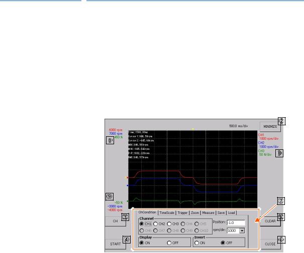
Main screen of not in-measurement mode (Waiting) is shown in Fig. 2-2 below with description.
Fig. 2-2: Main Screen (Not In-measurement Mode)
|
|
|
|
|
|
|
|
|
|
|
|
|
|
|
|
|
|
|
|
|
|
|
|
|
|
|
|
|
|
|
|
|
|
|
|
|
|
|
|
|
|
|
|
|
|
|
|
|
|
|
|
|
|
|
|
|
|
|
|
|
|
|
|
|
|
|
|
|
|
|
|
|
|
|
|
|
|
|
|
|
|
|
|
|
|
|
|
|
|
|
|
|
|
|
|
|
|
|
|
|
|
|
|
|
|
|
|
|
|
|
|
|
|
|
|
|
|
|
|
|
|
|
|
|
|
|
|
|
|
|
|
|
|
|
|
|
|
|
|
|
|
|
|
|
|
|
|
|
|
|
|
|
|
|
|
|
|
|
|
|
|
|
|
|
|
|
|
|
|
|
|
|
|
|
|
|
|
|
|
|
|
|
|
|
|
|
|
|
|
|
|
|
|
|
|
|
|
|
|
|
|
|
|
|
|
|
|
|
|
|
|
|
|
|
|
|
|
|
|
|
|
|
|
|
|
|
|
|
|
|
|
|
|
|
|
|
|
|
|
|
|
|
|
|
|
|
|
|
|
|
|
|
|
|
|
|
|
|
|
|
|
|
|
|
|
|
|
|
|
|
|
Name |
|
Function |
||||||||||||||
|
|
Waveform display area |
Displays measured data waveform. When the data is not yet acquired soon |
|||||||||||||
|
|
|
after the startup or when the data is cleared, nothing is shown here. |
|||||||||||||
|
|
|
At the upper left of the area, measurement value obtained by the cursor |
|||||||||||||
|
|
|
measurement function is displayed. |
|||||||||||||
|
|
{MINIMIZE} button |
Minimizes the PP oscilloscope application. |
|||||||||||||
|
|
{CH} button |
Opens the Channel Setting window. (For details of the Channel Setting |
|||||||||||||
|
|
|
window, refer to section 2.3.1 “Channel Setting Window” on page 2-4) |
|||||||||||||
|
|
{START} button |
Starts the data measurement. |
|||||||||||||
|
|
|
|
|||||||||||||
|
|
{CLEAR} button |
Deletes the displayed data waveform. |
|||||||||||||
|
|
|
|
|||||||||||||
|
|
{CLOSE} button |
Terminates the PP oscilloscope. |
|||||||||||||
|
|
Condition setting panel |
Enables to set various conditions. Touching the upper tab enables to open |
|||||||||||||
|
|
|
the setting screen corresponding to each parameter. (For details of each |
|||||||||||||
|
|
|
condition setting, refer to section 2.3.2 “CH Display Setting Panel” on page 2- |
|||||||||||||
|
|
|
8 to section 2.3.4 “Trigger Setting Panel” on page 2-11.) |
|||||||||||||
|
|
Maximum display value |
Displays values and units at the uppermost of waveform display area by each |
|||||||||||||
|
|
|
channel. |
|||||||||||||
|
|
Minimum display value |
Displays values and units at the lowermost of waveform display area by each |
|||||||||||||
|
|
|
channel. |
|||||||||||||
|
|
Reference unit |
Displays the reference unit by each channel. For details of the reference unit, |
|||||||||||||
|
|
|
refer to section 5.2 “Reference Unit” on page 5-2. |
|||||||||||||
On the Main screen, information by channels is displayed in each specific color; for example in Fig. 2-2, information on CH3 is displayed in green, where the reference unit is 50%/div, the maximum display value is 450%, and the minimum display value is -50%.
2-2 |
14 of 48 |
HW1481803
165467-1CD |
|
|
|
Pendant Oscilloscope |
2 |
Setting and Operation for Data Measurement |
|
Function |
2.2 |
Main Screen Configuration |
|
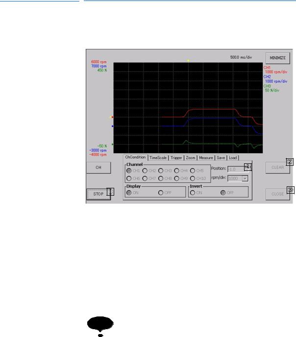
2.2.2 Main Screen (In-measurement Mode)
Main screen of In-measurement mode is shown in Fig. 2-3. In this mode, the states of some buttons are changed. Here describes such buttons;
Fig. 2-3: Main Screen (In-measurement Mode)
|
|
|
|
|
|
|
|
|
|
|
|
|
|
|
|
|
|
|
|
|
|
|
|
|
|
|
|
|
|
|
|
|
|
|
|
|
|
|
|
|
|
|
|
|
|
|
|
|
|
|
|
|
|
|
|
|
|
|
|
|
|
|
|
|
|
|
|
|
|
|
|
|
|
|
|
|
|
|
|
|
|
|
|
|
|
|
|
|
|
|
|
|
|
|
|
|
|
|
|
|
|
|
|
|
|
|
|
|
|
|
|
Name |
|
|
|
Function |
|
|
|
|
|
|
|||
|
|
|
|
|
|
||||||||
|
|
{STOP} button |
|
|
Switched from the {START} button, stops the data measurement. |
|
|||||||
|
|
|
|
|
|
|
|||||||
|
|
{CLEAR} button |
|
|
In measurement mode, the button operation is disabled. |
|
|||||||
|
|
|
|
|
|
|
|||||||
|
|
{CLOSE} button |
|
|
In measurement mode, the button operation is disabled. |
|
|||||||
|
|
|
|
|
|
|
|||||||
|
|
Condition setting panel |
|
|
In measurement mode, the operation on tab is disabled. |
|
|||||||
|
|
|
|
|
|
|
|
|
|
||||
|
|
|
|
|
|
|
|
|
|
||||
|
|
|
|
|
|
|
|
|
|
||||
|
|
|
|
|
|
|
|
Soon after switching the buttons {START} / {STOP}, button |
|
||||
|
|
|
|
NOTE |
operation is not available for a certain period of time to |
|
|||||||
|
|
|
|
avoid continuous pressing of the buttons. |
|
||||||||
|
|
|
|
|
|
|
|
When the buttons {START} / {STOP} are disabled, wait until |
|
||||
|
|
|
|
|
|
|
|
the operation becomes available. |
|
||||
|
|
|
|
|
|
|
|
|
|
|
|
|
|
|
|
|
|
|
|
|
|
|
|
|
|
|
|
2-3 |
15 of 48 |
HW1481803
 Loading...