


Model No. WESY6863.4 Serial No.
Write the serial number in the space above for future reference.
 Serial Number Decal (under seat)
QUESTIONS?
As a manufacturer, we are committed to providing complete customer satisfaction. If you have questions, or if a part is damaged or missing, PLEASE CONTACT OUR CUSTOMER SERVICE DEPARTMENT DIRECTLY.
CALL1-877TOLL-992-FREE:-5999 Mon.–Fri., 6 a.m.–6 p.m. MST
ON THE WEB: www.weiderservice.com
CAUTION
Read all precautions and instructions in this manual before using this equipment. Save this manual for future reference.
USER’S MANUAL


 Visit our website at
 www.weiderfitness.com new products, prizes, fitness tips, and much more!

TABLE OF CONTENTS
WARNING DECAL PLACEMENT . . . . . . . . . . . . . . . . . . . . . . . . . . . . . . . . . . . . . . . . . . . . . . . . . . . . . . . . . . . . . 3 IMPORTANT PRECAUTIONS . . . . . . . . . . . . . . . . . . . . . . . . . . . . . . . . . . . . . . . . . . . . . . . . . . . . . . . . . . . . . . . . 4 BEFORE YOU BEGIN . . . . . . . . . . . . . . . . . . . . . . . . . . . . . . . . . . . . . . . . . . . . . . . . . . . . . . . . . . . . . . . . . . . . . . 5 ASSEMBLY . . . . . . . . . . . . . . . . . . . . . . . . . . . . . . . . . . . . . . . . . . . . . . . . . . . . . . . . . . . . . . . . . . . . . . . . . . . . . . .6 UPPER CABLE ADJUSTMENT . . . . . . . . . . . . . . . . . . . . . . . . . . . . . . . . . . . . . . . . . . . . . . . . . . . . . . . . . . . . . .14 ADJUSTMENTS . . . . . . . . . . . . . . . . . . . . . . . . . . . . . . . . . . . . . . . . . . . . . . . . . . . . . . . . . . . . . . . . . . . . . . . . . . 15 CABLE DIAGRAM . . . . . . . . . . . . . . . . . . . . . . . . . . . . . . . . . . . . . . . . . . . . . . . . . . . . . . . . . . . . . . . . . . . . . . . . .18 TROUBLESHOOTING . . . . . . . . . . . . . . . . . . . . . . . . . . . . . . . . . . . . . . . . . . . . . . . . . . . . . . . . . . . . . . . . . . . . .19 EXERCISE GUIDELINES . . . . . . . . . . . . . . . . . . . . . . . . . . . . . . . . . . . . . . . . . . . . . . . . . . . . . . . . . . . . . . . . . . 20 ORDERING REPLACEMENT PARTS . . . . . . . . . . . . . . . . . . . . . . . . . . . . . . . . . . . . . . . . . . . . . . . . . .Back Cover LIMITED WARRANTY . . . . . . . . . . . . . . . . . . . . . . . . . . . . . . . . . . . . . . . . . . . . . . . . . . . . . . . . . . . . . . Back Cover
Note: A PART IDENTIFICATION CHART and a PART LIST/EXPLODED DRAWING are attached in the center of this manual. Remove the PART IDENTIFICATION CHART and PART LIST/EXPLODED DRAWING before beginning assembly.
2
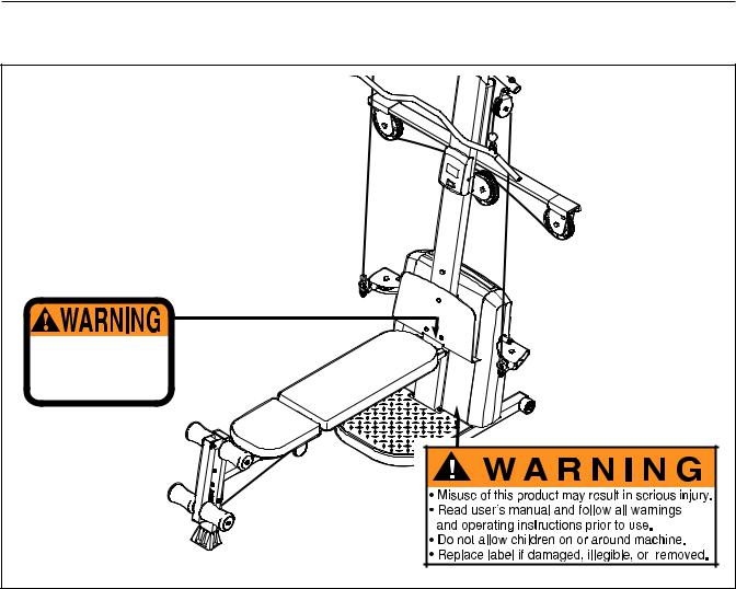
WARNING DECAL PLACEMENT
The decals shown here have been placed on the resistance system. If a decal is missing or illegible, please call the toll-free telephone number on the front cover of this manual and order a free replacement decal. Apply the decal in the location shown.
fingers clear of this area.
3

IMPORTANT PRECAUTIONS
|
WARNING: To reduce the risk of serious injury, read the following important precautions |
||
before using the resistance system. |
|
||
1. |
Read all instructions in this manual and all |
10. The crossbar on the top frame is not |
|
|
warnings on the resistance system before |
designed to be used for pull-up exercises. Do |
|
|
using the resistance system. Use the resist- |
not hang on the crossbar. |
|
|
ance system only as described in this manual. |
11. Pull on the lower cable only while sitting on |
|
2. |
It is the responsibility of the owner to ensure |
||
the bench or standing on the base plate. Pull |
|||
|
that all users of the resistance system are |
on the high cables only while sitting on the |
|
|
adequately informed of all precautions. |
bench, with the seat in one of the three posi- |
|
3. |
The resistance system is intended for home |
tions closest to the upright base, or while |
|
standing on the base plate. |
|||
|
use only. Do not use the resistance system in |
|
|
|
any commercial, rental, or institutional setting. 12. The resistance system is designed to be |
||
4. |
Keep the resistance system indoors, away |
used with the included resistance. Do not |
|
use the resistance system with any other |
|||
|
from moisture and dust. Place the resistance |
type of resistance. |
|
|
system on a level surface, with a mat |
|
|
|
beneath it to protect the floor or carpet. Make |
13. Always disconnect the lat bar from the high |
|
|
sure that there is enough clearance around |
cables when performing an exercise that |
|
|
the resistance system to mount, dismount, |
does not require it. |
|
|
and use the resistance system. |
14. Make sure the storage knob is in place and |
|
5. |
Inspect and properly tighten all parts regular- |
||
fully tightened each time the resistance sys- |
|||
|
ly. Replace any worn parts immediately. |
tem is used. |
|
6. |
Keep children under 12 and pets away from |
15. Make sure that the cables remain on the pul- |
|
|
the resistance system at all times. |
leys at all times. If the cables bind as you are |
|
7. |
Keep hands and feet away from moving parts. |
exercising, stop immediately and make sure |
|
that the cables are on the pulleys. Replace all |
|||
8. |
Always wear athletic shoes for foot protec- |
cables at least every two years. |
|
|
|||
|
tion while exercising. |
16. Do not pull on the cables while the resist- |
|
9. |
The resistance system is designed to sup- |
ance level is being adjusted. |
|
|
|||
|
port a maximum user weight of 300 pounds. |
17. If you feel pain or dizziness while exercising, |
|
stop immediately and begin cooling down. WARNING: Before beginning this or any exercise program, consult your physician. This
is especially important for persons over the age of 35 or persons with pre-existing health problems. Read all instructions before using. ICON assumes no responsibility for personal injury or property damage sustained by or through the use of this product.
4
BEFORE YOU BEGIN
Thank you for selecting the innovative WEIDER® PLATINUM XP600 resistance system. The resistance system offers a selection of stations designed to devel- op every major muscle group of the body. Whether your goal is to tone your body, build dramatic muscle size and strength, or improve your cardiovascular system, the resistance system will help you to achieve the specific results you want.
For your benefit, read this manual carefully before using the resistance system. If you have questions after reading this manual, see the front cover of this
manual. To help us assist you, please note the product model number and serial number before calling. The model number is WESY6863.4. The serial number can be found on a decal attached to the resistance system (see the front cover of this manual).
To avoid a registration fee for any service needed under warranty, you must register the resistance system at www.weiderservice.com/registration.
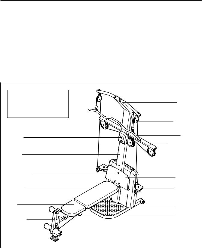
Before reading further, please review the drawing below and familiarize yourself with the parts that are labeled.
ASSEMBLED DIMENSIONS: |
|
||||
Height: |
82 in. |
/ |
208 cm |
Crossbar |
|
Width: |
66 in. |
/ |
168 cm |
||
|
|||||
Depth: |
80 in. |
/ |
203 cm |
|
|
|
|
|
|
High Pulley |
|
Console |
|
|
|
Lat Bar |
|
|
|
|
|
||
|
|
|
|
Resistance Bar |
|
Upright |
|
|
|
|
|
Storage Knob |
|
|
Foot Plate |
||
|
|
|
|
||
Backrest |
|
|
|
Low Pulley |
|
Seat |
|
|
|
Base Plate |
|
|
|
|
|
||
Leg Lever |
|
|
|
Seat Knob |
|
|
|
|
|
||
|
|
|
|
5 |
|
ASSEMBLY
Make Things Easier for Yourself
Everything in this manual is designed to ensure that the weight system can be assembled successfully by almost anyone. However, the weight system has many parts and the assembly process will take time. By setting aside plenty of time, assembly will go smoothly.
To hire an authorized service technician to assemble the weight system, call toll-free 1-800-445-2480.
Before beginning assembly, carefully read the following information and instructions:
•Place all parts in a cleared area and remove the packing materials. Do not dispose of the packing materials until assembly is completed.
•Tighten all parts as you assemble them, unless instructed to do otherwise.
•As you assemble the weight bench, make sure all parts are oriented as shown in the drawings.
•Assembly requires two people.
•For help identifying small parts, use the PART IDENTIFICATION CHART.
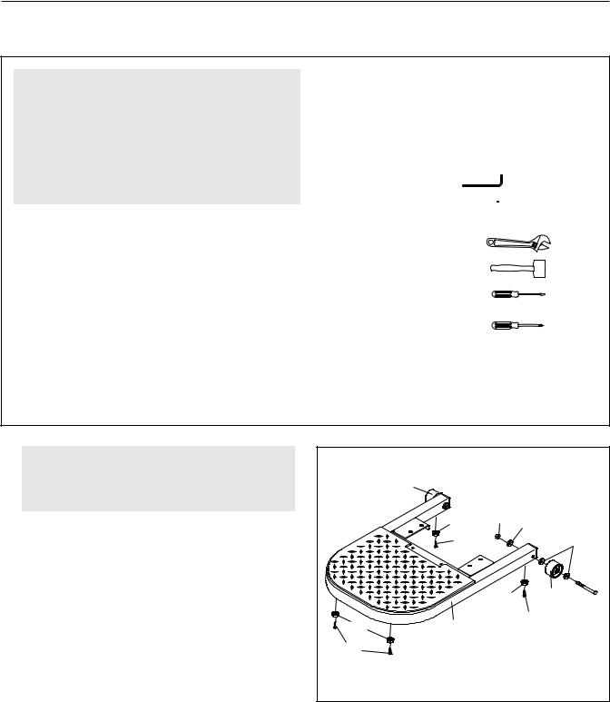
The included hex key(s) and grease, and the following tools (not included) may be required for assembly:
• Two adjustable wrenches
• One rubber mallet
• One standard screwdriver
• One Phillips screwdriver
• Clear tape or masking tape, and soapy water.
Assembly will be more convenient if you have a socket set, a set of open-end or closed-end wrenches, or a set of ratchet wrenches.
1. |
Before beginning assembly, make sure that |
1 |
|
|
|
|
|
|
|
|
|
|
|
||
|
you have read and understand the informa- |
|
21 |
|
|
|
|
|
tion in the box above. |
|
|
|
|
|
|
|
|
|
|
|
|
|
|
|
Attach a Wheel (21) to the Base (1) with a 3/8” x |
|
20 |
92 |
75 |
|
|
|
|
104 |
|
|
|
75 |
|
|
3 1/2” Bolt (90), three 3/8” SAE Washers (75), |
|
|
|
|
||
|
|
|
|
|
|
|
|
|
and a 3/8” Nylon Jamnut (92). Do not overtight- |
|
|
|
|
|
|
|
en the Jamnut; the Wheel must be able to turn |
|
|
|
|
|
|
|
easily. |
|
|
20 |
|
21 |
90 |
|
|
|
|
|
|||
|
Attach the other Wheel (21) to the Base (1) in |
|
|
|
104 |
|
|
|
19 |
1 |
|
|
|
||
|
the same manner. |
|
|
|
|
||
|
104 |
|
|
|
|
|
|
|
Attach two Plastic Feet (19) and two Large Plastic |
|
|
|
|
|
|
|
|
|
|
|
|
|
|
|
Feet (20) to the Base (1) with four #8 x 3/4” |
|
|
|
|
|
|
|
Screws (104). |
|
|
|
|
|
|
6
2. Attach the Upright (3) to the Base (1) with two |
2 |
|
|
|
3/8” x 2 3/4” Carriage Bolts (88), two 3/8” x 3” |
|
|
|
|
|
|
|
|
|
Bolts (87), and four 3/8” Nylon Locknuts (73) as |
|
|
|
|
shown. Note: This step will be easier to com- |
|
|
|
|
plete if the Upright and Base are tipped on |
|
|
|
|
their sides. |
|
|
|
|
|
|
|
3 |
|
|
|
|
87 |
|
|
|
|
73 |
|
|
|
|
73 |
|
|
|
|
73 |
|
|
|
|
1 |
|
|
|
|
88 |
|
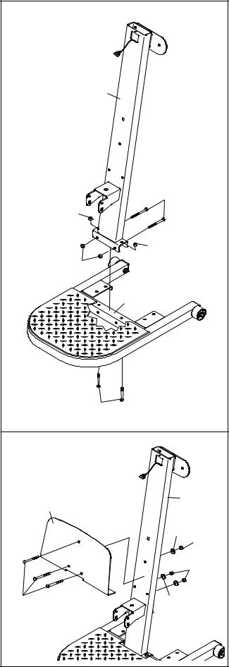
3. Attach the Foot Plate (4) to the Upright (3) with |
3 |
|
|
|
three 3/8” x 2 3/4” Carriage Bolts (88), three 3/8” |
|
|
|
|
|
|
|
|
|
SAE Washers (75), and three 3/8” Nylon |
|
|
|
|
Locknuts (73). |
|
|
|
|
|
|
4 |
3 |
|
|
|
|
|
|
|
|
|
75 |
73 |
|
|
|
|
|
|
|
|
|
73 |
|
88 |
|
75 |
|
|
7 |
|
|
|
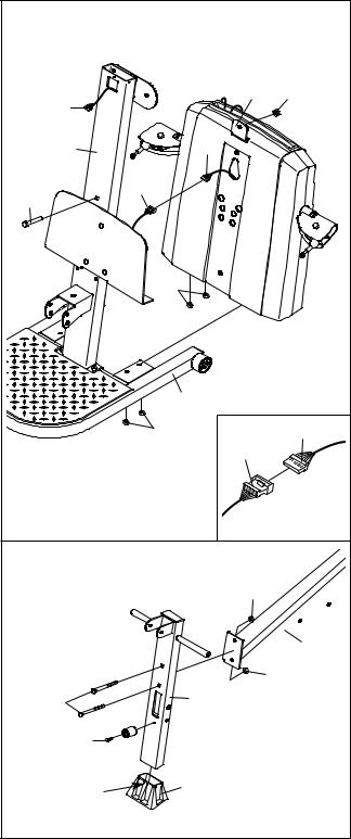
4. Insert the connector of the lower wire harness (A) |
4 |
|
|
|
|
into the socket of the Upper Wire Harness (13). |
|
|
|
|
|
|
|
|
|
|
|
The connector should slide easily into the |
|
|
|
|
|
socket and snap into place. If the connector |
|
|
|
|
|
does not slide easily and snap into place, turn the |
|
|
|
6 |
78 |
connector over and then insert it. |
|
13 |
|
||
|
|
|
|
|
|
Make sure that the connector and wire appear as |
|
|
|
|
|
shown in the inset drawing. IF THE CONNEC- |
|
3 |
|
A |
|
TOR IS NOT INSERTED PROPERLY, THE CON- |
|
|
|
|
|
SOLE MAY BE DAMAGED WHEN THE POWER |
|
|
13 |
|
|
IS TURNED ON. |
79 |
|
|
|
|
|
|
|
|
||
Pull the excess lower wire harness (A) out of |
|
|
|
|
|
the Mech Assembly (6) and push it and the |
|
|
|
|
|
Upper Wire Harness (13) into the Upright (3). |
|
|
71 |
|
|
Insert the Mech Assembly (6) into the Base (1). |
|
|
|
|
|
|
|
|
|
|
|
Attach the Mech Assembly to the Upright (3) with |
|
|
|
|
|
a 1/2” x 3” Carriage Bolt (79) and a 1/2” Nylon |
|
|
|
|
|
Locknut (78). Do not tighten the Locknut yet. |
|
|
|
|
|
Attach the Mech Assembly (6) to the Base (1) |
|
|
|
1 |
|
with the four M10 Nylon Locknuts (71). |
|
|
|
|
|
|
|
|
|
|
|
Tighten the 1/2” Nylon Locknut (78). |
|
|
71 |
13 |
A |
|
|
|
|
||
|
|
|
|
|
|
5. Press the Front Leg Foot (29) onto the bottom of |
5 |
|
|
|
|
the Front Leg (31). Note that the front of the |
|
|
|
|
|
|
|
|
|
|
|
Front Leg Foot is taller than the back. |
|
|
|
92 |
|
|
|
|
|
|
|
Attach the Leg Lever Bumper (30) to the Front |
|
|
|
|
|
Leg (31) with a #8 x 3/4” Screw (104). |
|
|
|
|
23 |
|
|
|
|
|
|
Attach the Bench Rail (23), with the hook on the |
|
|
|
|
92 |
bottom, to the Front Leg (31) with two 3/8” x 2” |
|
|
|
|
|
|
91 |
|
31 |
|
|
Carriage Bolts (91) and two 3/8” Nylon Jamnuts |
|
|
|
||
(92). |
|
104 |
|
|
|
|
|
30 |
|
|
|
|
|
|
|
|
|
|
|
Front |
|
29 |
|
|
|
|
|
|
|
|
8 |
|
|
|
|
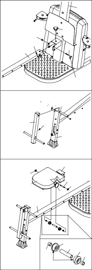
6.Grease a 3/8” x 4” Bolt (86) using the included grease pack. Attach the Bench Rail (23) to the Upright (3) with the Bolt and a 3/8” Nylon Jamnut
(92).Make sure the Bolt is inserted through the indicated hole in the Bench Rail. Do not overtighten the Jamnut; the Bench Rail must be able to pivot easily.
Tighten the Storage Knob (26) into the Upright (3) and the Bench Rail (23).
7.Grease a 3/8” x 2 3/4” Bolt (93). Orient the Leg Lever (32) with the slot on the side shown. Attach the Leg Lever to the Front Leg (31) with the Bolt and a 3/8” Nylon Locknut (73). Do not overtighten the Locknut; the Leg Lever must be able to pivot easily.
8.Pull out the Seat Knob (43) as far as it will go, and set the Seat Carriage (48) on the Bench Rail (23).
Loosely attach two 8mm Metal Spacers (45), a 60mm Metal Spacer (44), and two Bearing Wheels (46) to the center holes in the Seat Carriage (48) with two M8 Flange Nuts (47) and the M8 x 114mm Axle (102). Make sure that the serrated edge of the Flange Nuts are against the Seat Carriage.
While a second person presses down on the Seat (41), hold the wheel assembly firmly against the bottom of the Bench Rail (23) and properly tighten the M8 Flange Nuts (47). Make sure that three threads are extending past the Nuts, and that the wide sides of all six Bearing Wheels
(46)are pressed against the Bench Rail.
Engage the Seat Knob (not shown) into an adjustment hole in the Bench Rail (23).
9
6
7
8
|
|
3 |
|
|
26 |
|
73 |
|
|
Hole |
86 |
23 |
|
|
|
|
Grease
93 Grease 


32 |
Slot |
73 |
|
|
|
|
|
31 |
|
48 |
47 |
|
41 |
102 |
47 |
|
|
43 |
|
23 |
46 |
44 |
46 |
|
45 |
|
45 |
|
|
|
|
|
Wide |
|
|
|
Side |
|
|
|
 Loading...