


8630
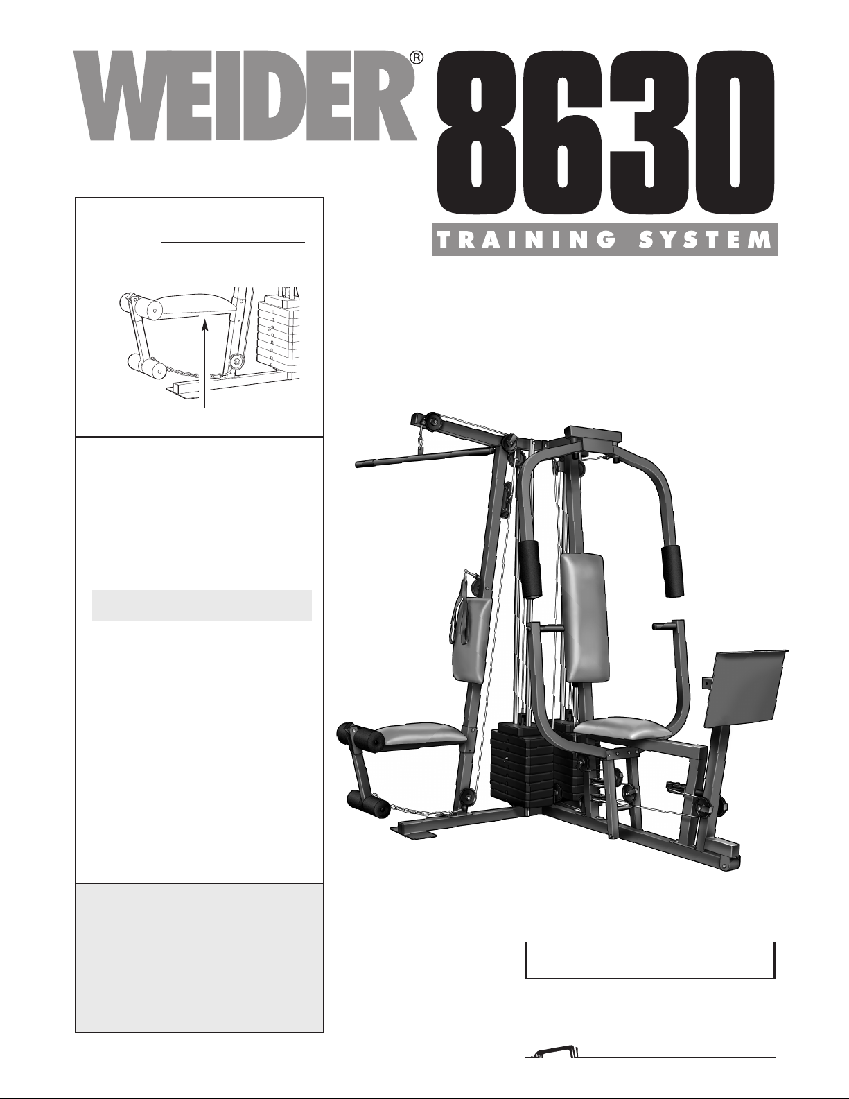
USER'S MANUAL
QUESTIONS?
As a manufacturer, we are com-
mitted to providing complete
customer satisfaction. If you
have questions, or if there are
missing parts, please call:
1-888-936-4266
Mon.–Fri. 8h00 until 18h30 EST
(excluding holidays).
Model No. WESY8630C4
Serial No.
Write the serial number in the space
a
bove for future reference.
Patent Pending
CAUTION
Read all precautions and instruc-
tions in this manual before using
this equipment. Save this manual
for future reference.
Serial Number Decal (Under Seat)
Visit our website at
www.proform.com
new products, prizes,
fitness tips, and much more!
Visit our website at
www.healthrider.com
new products, prizes,
fitness tips, and much more!

2
TABLE OF CONTENTS
LIMITED WARRANTY . . . . . . . . . . . . . . . . . . . . . . . . . . . . . . . . . . . . . . . . . . . . . . . . . . . . . . . . . . . . . . . . . . . . . . .2
IMPORTANT PRECAUTIONS . . . . . . . . . . . . . . . . . . . . . . . . . . . . . . . . . . . . . . . . . . . . . . . . . . . . . . . . . . . . . . . .3
BEFORE YOU BEGIN . . . . . . . . . . . . . . . . . . . . . . . . . . . . . . . . . . . . . . . . . . . . . . . . . . . . . . . . . . . . . . . . . . . . . .4
ASSEMBLY . . . . . . . . . . . . . . . . . . . . . . . . . . . . . . . . . . . . . . . . . . . . . . . . . . . . . . . . . . . . . . . . . . . . . . . . . . . . . . .5
H
OW TO USE THE TRAINING SYSTEM . . . . . . . . . . . . . . . . . . . . . . . . . . . . . . . . . . . . . . . . . . . . . . . . . . . . . . .22
WEIGHT RESISTANCE CHART . . . . . . . . . . . . . . . . . . . . . . . . . . . . . . . . . . . . . . . . . . . . . . . . . . . . . . . . . . . . . .24
TROUBLE-SHOOTING AND MAINTENANCE . . . . . . . . . . . . . . . . . . . . . . . . . . . . . . . . . . . . . . . . . . . . . . . . . . .25
CABLE DIAGRAMS . . . . . . . . . . . . . . . . . . . . . . . . . . . . . . . . . . . . . . . . . . . . . . . . . . . . . . . . . . . . . . . . . . . . . . .26
ORDERING REPLACEMENT PARTS . . . . . . . . . . . . . . . . . . . . . . . . . . . . . . . . . . . . . . . . . . . . . . . . . .Back Cover
Note: A PART IDENTIFICATION CHART and a PART LIST/EXPLODED DRAWING are attached in the center of
this manual. Remove the PART IDENTIFICATION CHART and the PART LIST/EXPLODED DRAWING before
beginning assembly.
WEIDER is a registered trademark of ICON Health & Fitness, Inc.
LIMITED WARRANTY
ICON OF/DU CANADA INC., (ICON), warrants this product to be free from defects in workmanship and mate-
rial, under normal use and service conditions, for a period of one (1) year from the date of purchase. This war-
ranty extends only to the original purchaser. ICON's obligation under this warranty is limited to replacing or
repairing, at ICON's option, the product at one of its authorized service centers. All products for which war-
ranty claim is made must be received by ICON at one of its authorized service centers with all freight and other
transportation charges prepaid, accompanied by sufficient proof of purchase. All returns must be pre-autho-
rized by ICON. This warranty does not extend to any product or damage to a product caused by or attribut-
able to freight damage, abuse, misuse, improper or abnormal usage or repairs not provided by an ICON autho-
rized service center
, to products used for commercial or rental purposes, or to products used as store display
models. No other warranty beyond that specifically set forth above is authorized by ICON.
ICON is not responsible or liable for indirect, special or consequential damages arising out of or in connection
with the use or performance of the product or damages with respect to any economic loss, loss of property,
loss of revenues or profits, loss of enjoyment or use, costs of removal, installation or other consequential dam-
ages of whatsoever nature. Some provinces do not allow the exclusion or limitation of incidental or conse-
quential damages. Accordingly, the above limitation may not apply to you. The warranty extended hereunder
is in lieu of any and all other warranties and any implied warranties of merchantability or fitness for a particu-
lar purpose is limited in its scope and duration to the terms set forth herein. Some provinces do not allow lim-
itations on how long an implied warranty lasts. Accordingly, the above limitation may not apply to you.
The warranty extended hereunder is in lieu of any and all other warranties and any implied warranties of mer-
chantability or fitness for a particular purpose is limited in its scope and duration to the terms set forth herein.
This warranty gives you specific legal rights. You may also have other rights which vary from province to
province or so specified by the retailer of your equipment.
ICON OF CANADA, 900 de l’Industrie, St-Jérôme, QC J7Y 4B8

3
IMPORTANT PRECAUTIONS
W
ARNING: To reduce the risk of serious injury, read the following important precautions before
using the training system.
1. It is the responsibility of the owner to ensure
that all users of the training system are ade-
quately informed of all precautions.
2. Read all instructions in this manual and in
the accompanying literature before using the
training system.
3. Use the training system only on a level sur-
face. Place a mat beneath the training sys-
tem to protect the floor or carpet.
4. Inspect and tighten all parts often. Replace
any worn parts immediately.
5. Keep children under the age of 12 and pets
away from the training system at all times.
6. Never release the press arm, butterfly arms,
leg lever, leg press plate, lat bar, ab strap, or
nylon strap while weights are raised. The
weights will fall with great force.
7. Keep hands and feet away from moving parts.
8. Always wear athletic shoes for foot protec-
tion.
9. Always stand on the foot plate when per-
forming an exercise that could cause the
training system to tip.
10. When using the leg press station, always be
sure that the lock pin is fully inserted and
that the lock pin is clipped in place on the
adjustment tube (see page 23).
11. Make sure that the cables remain on the pul-
leys at all times. If the cables bind while you
are exercising, stop immediately and make
sure that the cables are on all of the pulleys.
12. Always disconnect the lat bar from the train
-
ing system when performing an exercise that
does not use the lat bar.
13. If you feel pain or dizziness at any time while
exercising, stop immediately and begin cool-
ing down.
14. The training system is intended for home use
only. Do not use the training system in any
commercial, rental, or institutional setting.
15. The decal shown
at the right has
been attached to
the training sys-
tem in the two
locations shown
on page 4. If a
decal is missing
or illegible,
please call toll-
free 1-888-936-
4266 to order a
free replacement
decal. Apply the
decal in the loca-
tion shown.
WARNING: Before beginning this or any exercise program, consult your physician. This is especially
important for persons over the age of 35 or persons with pre-existing health problems. Read all
instructions before using. ICON assumes no responsibility for personal injury or property damage
sustained by or through the use of this product.
4
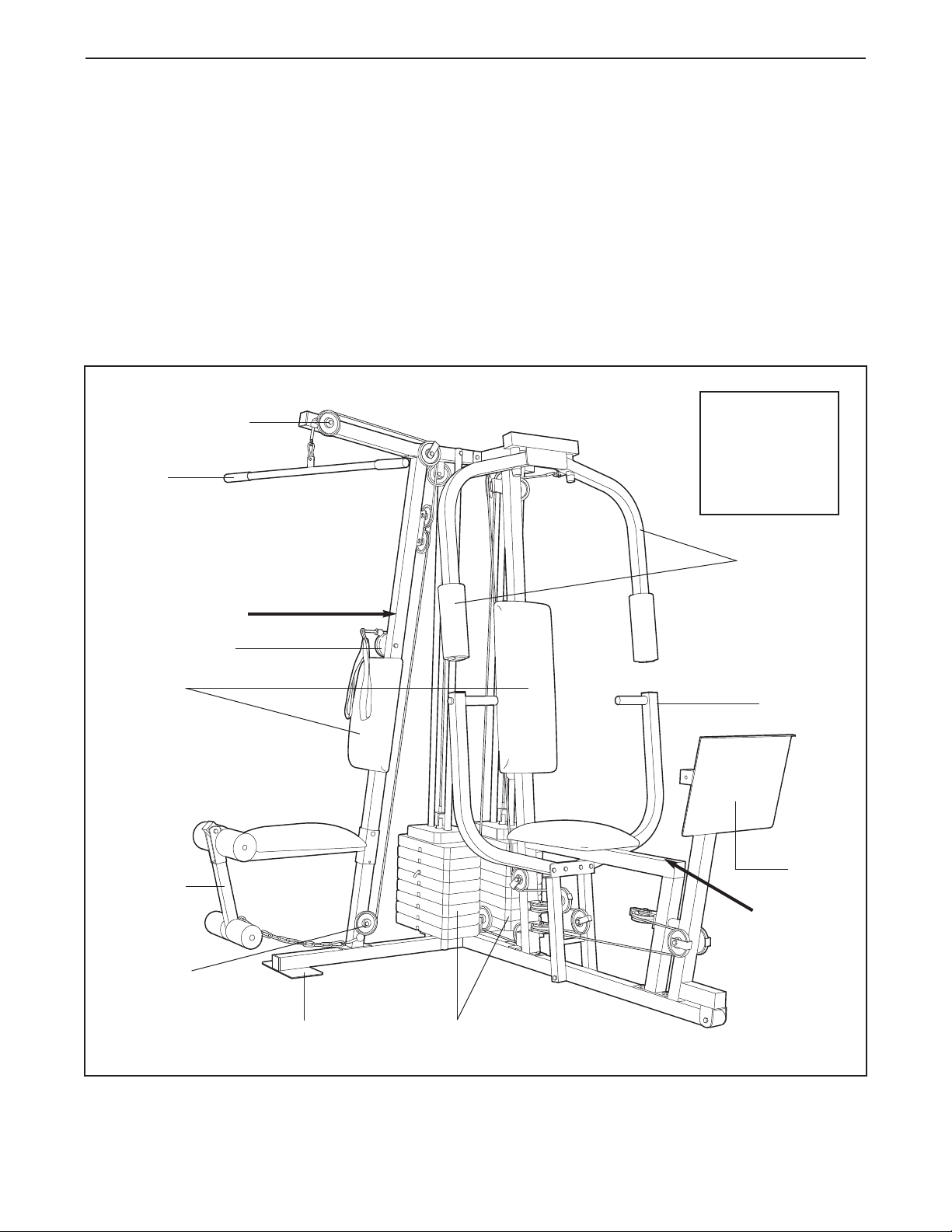
BEFORE YOU BEGIN
ASSEMBLED
DIMENSIONS:
Height: 78 in.
Width: 64 in.
Length: 70 in.
Foot Plate
Low Pulley
Station
High Pulley Station
Lat Bar
Leg Lever
Butterfly Arms
Press Arm
Weight Stacks
Backrests
Leg Press
Plate
Ab Pulley Station
WARNING DECAL
WARNING
DECAL
Thank you for selecting the versatile WEIDER
®
8630
t
raining system. The WEIDER
®
8
630 offers a selection
of weight stations designed to develop every major
muscle group of the body. Whether your goal is to tone
your body, build dramatic muscle size and strength, or
improve your cardiovascular system, the WEIDER
®
8630 will help you to achieve the specific results you
want.
For your benefit, read this manual carefully before
using the WEIDER
®
8630 training system. If you
have additional questions, please call our Customer
Service Department toll-free at 1-888-936-4266,
M
onday through Friday, 8h00 until 18h00 Eastern
Time (excluding holidays). To help us assist you,
please note the product model number and serial
number before calling. The model number is
WESY8630C4. The serial number can be found on a
decal attached to the WEIDER
®
8630 (see the front
cover of this manual).
Before reading further, please review the drawing
below and familiarize yourself with the parts that are
labeled.

5
ASSEMBLY
Make sure you have the following tools:
• Two adjustable wrenches
• One standard screwdriver
• One phillips screwdriver
• One rubber mallet
• You will also need grease or petroleum jelly, a
small amount of soapy water, and clear tape or
masking tape.
Note: Assembly will be more convenient if you have
a socket set, a set of open-end or closed-end
wrenches, or a set of ratchet wrenches.
How to Identify Parts
To help you identify the small parts used in assembly,
we have included a PART IDENTIFICATION CHART
in the center of this manual. Place the chart on the
floor and use it to easily identify parts during each
assembly step.
Note: Some small parts may have
been pre-attached. If a part is not in the parts
bag, check to see if it has been pre-attached.
How to Orient Parts
As you assemble the training system, make sure that
all parts are oriented exactly as shown in the drawings.
Tightening Parts
Tighten all parts as you assemble them, unless
instructed to do otherwise.
Questions?
If you have questions after reading the assembly
instructions, please call our Customer Service
Department toll-free at 1-888-936-4266, Monday
through Friday, 8h00 until 18h00 Eastern Time
(excluding holidays).
Assembly Requires Two Persons
For your convenience and safety, assemble the
training system with the help of another person.
Set Aside Enough Time
Due to the many features of the training system,
the assembly process will require about six hours.
By setting aside plenty of time and by deciding to
make the task enjoyable, assembly will go smoothly.
You may want to assemble the training system over
a couple of evenings.
Select a Location for the Training
System
Because of its weight and size, the training system
should be assembled in the location where it will be
used. Make sure that there is enough room to walk
around the training system as you assemble it.
How to Unpack the Box
To make assembly as easy as possible, we have
divided the assembly process into four stages. The
parts needed for each stage are found in individual
bags. Important: W
ait until you begin each stage
to open the parts bag for that stage.
Place all
parts of the training system in a cleared area and
remove the packing materials. Do not dispose
of
the packing materials until assembly is completed.
Make Assembly Easier for Yourself
Everything in this manual is designed to
ensure that the training system can be
assembled successfully by anyone. Before
beginning assembly, make sure to read the
information on this page; this brief intro-
duction will save you much more time than
it takes to read it!
The Four Stages of the Assembly Process
Frame Assembly—You will begin by assembling
the base and the uprights that form the skeleton of
the training system.
Arm Assembly—During this stage you will
assemble the arms and the leg lever
.
Cable Assembly—During this stage you will
attach the cables and pulleys that connect the
arms to the weights.
Seat Assembly—During the final stage you will
assemble the seats and the backrests.

1.
Locate and open the parts bags labeled
“FRAME ASSEMBLY BAG ONE” and
“FRAME ASSEMBLY BAG TWO.”
Press two 2” Square Outer Caps (58) onto the
Weight Base (14) in the indicated locations.
Press a 2” Square Inner Cap (56) into the end
of the Weight Base.
Insert four 5/16” x 2 1/2” Carriage Bolts (49)
up through the Press Base (13). Insert two
5/16” x 2 1/2” Carriage Bolts up through the
Weight Base (14).
Attach the Press Base (13) to the Weight
Base (14) with two 5/16” x 2 3/4” Bolts (55),
two 5/16” Washers (20), and two 5/16” Nylon
Locknuts (40).
Do not tighten the Nylon
Locknuts yet.
2. Slide the Ab Upright (1) onto the indicated
5/16” x 2 1/2” Carriage Bolts (49) in the
Weight Base (14). Hand tighten two 5/16”
Nylon Locknuts (40) onto the Carriage Bolts.
Do not tighten the Nylon Locknuts yet.
Slide the Leg Press Upright (4) onto the indi-
cated 5/16” x 2 1/2” Carriage Bolts (49) in the
Weight Base (14). Hand tighten two 5/16”
Nylon Locknuts (40) onto the Carriage Bolts.
Do not tighten the Nylon Locknuts yet.
3. Press a 2” Square Inner Cap (56) into each
end of the Top Frame (2). Press a 2” Square
Inner Cap into each side of the Butterfly
Frame (3). Press two Inner Caps (98) into the
top of the Butterfly Frame.
Attach the Butterfly Frame (3) to the Top
Frame (2) with a 5/16” x 3” Bolt (92).
Be sure
that the Bolt is on the side shown.
Finish attaching the Butterfly Frame (3) to the
Top Frame (2) with a 5/16” Nylon Jam Nut
(91), a 5/16” x 2 3/4” Bolt (55), a 5/16”
Washer (20), and a 5/16” Nylon Locknut (40).
2
3
FRAME ASSEMBLY
6
1
4
40
40
49
49
13
2
3
14
55
40
20
56
56
56
56
92
98
91
1
56
58
58
55
20
49
40
49
13
1
4
Before you begin this step, make sure
that you have read all of the information
on page 5.

4. Slide the Front Seat Frame (8) onto the indi-
cated 5/16” x 2 1/2” Carriage Bolts (49) in the
P
ress Base (13). Hand tighten two 5/16”
Nylon Locknuts (40) onto the Carriage Bolts.
Attach the other end of the Front Seat Frame
(8) to the Leg Press Upright (4) with two 5/16”
x 2 3/4” Bolts (55), two 5/16” Washers (20),
and two 5/16” Nylon Locknuts (40).
Press a 2” Square Inner Cap (56) into the
Front Seat Frame (8).
5. Insert two Weight Guides (23) into one of the
brackets on the Weight Base (14). Attach the
lower ends of the Weight Guides with a 5/16”
x 6” Bolt (67), two 1/2” x 3/4” Spacers (69),
and a 5/16” Nylon Locknut (40).
Do not over-
tighten the Nylon Locknut.
Attach the other Weight Guides (23) in the
same manner.
6. Slide a Weight Bumper (27) onto each of the
Weight Guides (23).
Slide eight Weights (90) onto each set of
Weight Guides (23). Be sure that the pin
grooves are on the indicated side of each
stack of Weights.
7. Press a Weight Tube Bumper (26) into each
Weight Tube (25).
Insert a Weight Tube (25) into each stack of
Weights (90). Be sure that the pins on the
Weight Tubes are in the pin grooves in the
upper Weights.
7
6
7
FRAME ASSEMBLY
90
90
Pin
Grooves
27
27
23
23
26
25
Pin
Grooves
90
90
5
67
69
23
23
40
14
4
55
20
49
40
56
8
40
4
13
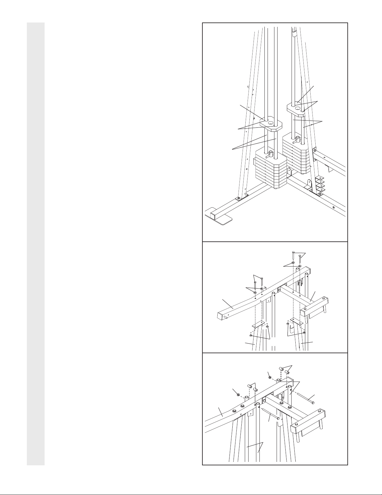
8. Lubricate the insides of the holes in the Top
Weights (24) as shown. Slide a Top Weight
o
nto each set of Weight Guides (23).
9. Attach the Top Frame (2) to the Ab Upright (1)
with two 5/16” x 2 3/4” Bolts (55), two 5/16”
Washers (20), and two 5/16” Nylon Locknuts
(40).
Do not tighten the Nylon Locknuts
yet.
Attach the Butterfly Frame (3) to the Leg
Press Upright (4) with two 5/16” x 2 3/4” Bolts
(55), two 5/16” Washers (20), and two 5/16”
Nylon Locknuts (40).
Do not tighten the
Nylon Locknuts yet.
10. Attach the upper ends of one set of Weight
Guides (23) to the Top Frame (2) with a 5/16”
x 6” Bolt (67), two 1/2” x 3/4” Spacers (69),
and a 5/16” Nylon Locknut (40).
Attach the upper ends of the other set of
Weight Guides (23) in the same manner.
Before continuing, firmly tighten all nylon
locknuts used in steps 1 through 10.
8
10
8
FRAME ASSEMBLY
23
Lubricate
Lubricate
23
23
69
40
67
67
40
2
69
24
24
23
9
55
55
20
20
40
40
4
3
2
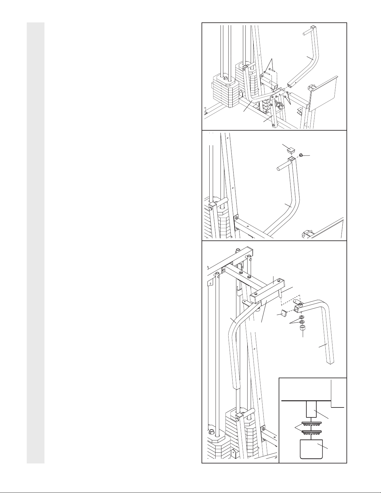
1
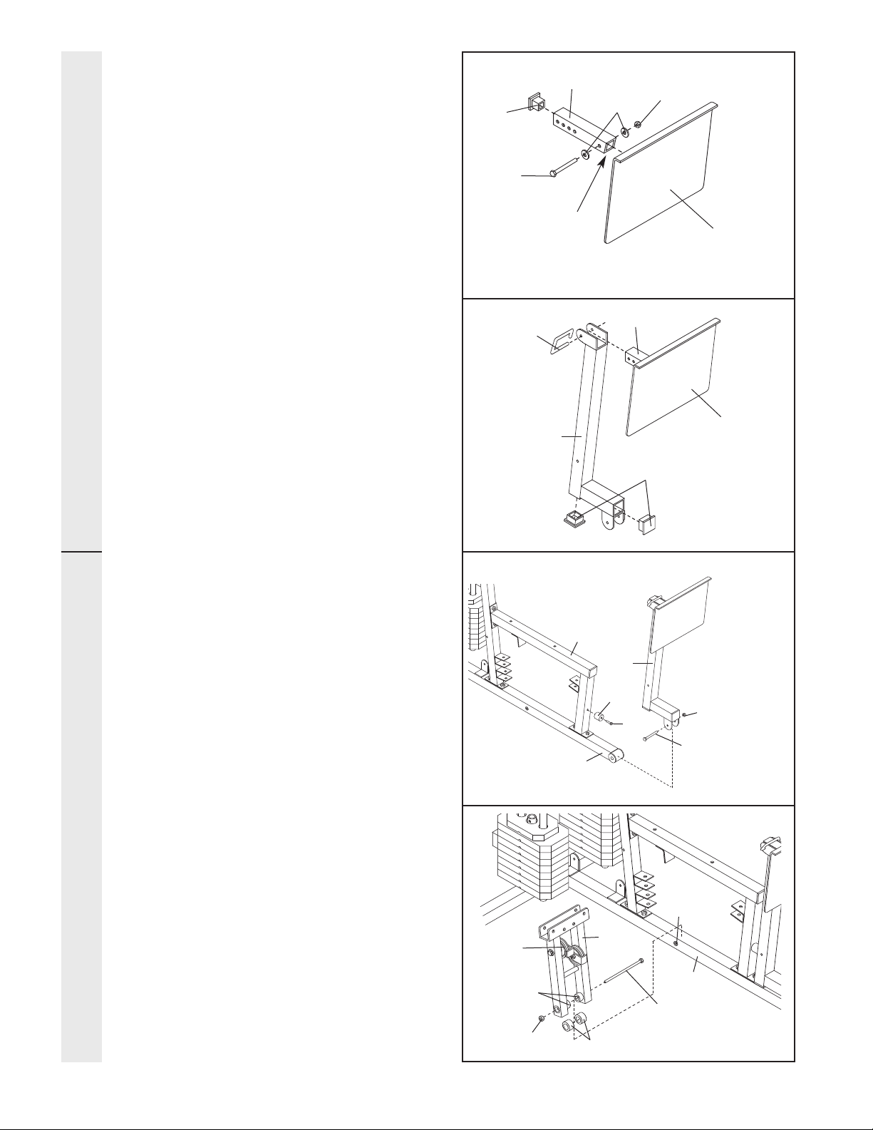
11. Attach the Leg Press Plate (11) to the
Adjustment Tube (10) with a 5/16” x 2 1/2”
B
olt (39), two 5/16” Washers (20), and a 5/16”
Nylon Locknut (40).
Be sure that the Leg
P
ress Plate and Adjustment Tube are ori-
ented as shown.
Press a 1 3/4” Square Inner Cap (48) into the
Adjustment Tube (10).
12. Attach the Adjustment Tube (10) to the Leg
Press Arm (9) with the Lock Pin (73).
Be sure
the Leg Press Plate (11) is oriented as
shown.
Press two 2” Square Inner Caps (56) into the
Leg Press
Arm (9).
13. Locate and open the parts bag labeled
“ARM ASSEMBLY.”
Attach the Leg Press Bumper (53) to the
Front Seat Frame (8) with the 1” Tap Screw
(72).
Lubricate the 3/8” x 3 1/4” Bolt (71). Attach
the Leg Press Arm (9) to the Press Base (13)
with the Bolt and a 3/8” Nylon Locknut (42).
14. Press a 1” x 7/8” Plastic Bushing (54) onto
each welded spacer on the Press Frame (12).
Slide the Press Frame onto the Press Base
(13) so that the Plastic Bushings are aligned
with the indicated tube. Note: This will be a
tight fit. Make sure that the high pulley is
on the side shown.
Lubricate the 3/8” x 8” Bolt (52). Attach the
Press Frame (12) to the Press Base (13) with
the Bolt and a 3/8” Nylon Locknut (42).
14
11
12
13
9
ARM ASSEMBLY
20
40
39
Angle
10
48
11
56
42
71—Lubricate
53
72
13
54
42
12
13
11
9
9
8
10
73
52
—
Lubricate
T
ube
W
elded
Spacers
High
Pulley
FRAME ASSEMBLY
10
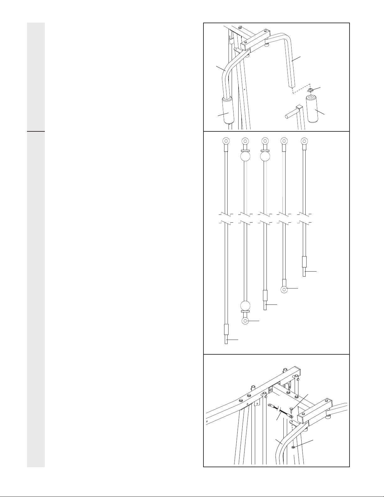
15. Attach a Press Arm (7) to one side of the
Press Frame (12) with two 5/16” x 2 1/2” Bolts
(
39) and two 5/16” Nylon Locknuts (40).
A
ttach the other Press Arm (7) to the Press
Frame (12) in the same manner.
16. Press a 1” Round Inner Cap (70) into one of
the Press Arms (7). Press a 1 3/4” Square
Inner Cap (48) into the Press Arm.
Repeat this step for the other Press
Arm (not
shown).
17. Lubricate both axles on the Butterfly Frame
(3).
Refer to the drawing and identify the Right Fly
Arm (5) and the Left Fly Arm (6).
Press a 1 3/4” Square Inner Cap (48) into the
upper end of the Left Fly Arm (6). Slide the Left
Fly Arm onto the indicated axle.
Note: Be care-
ful not to confuse the LeftFly Arm with the
Right Fly Arm (5). Be sure that the upper
end of the Left Fly Arm is behind the indi
-
cated bracket on the Butterfly Frame (3).
IMPORTANT NOTE: Before assembling the
1” Retainers (45) used in this step, be sure
that you thoroughly understand the step.
The Retainers can be assembled only once.
If they must be removed, you will need to
order new Retainers.
T
ap two 1” Retainers (45) and a 1” Round
Outer Cap (46) onto the axle. Be sure that
the teeth on the Retainers bend toward the
Round Outer Cap, as shown in the inset
drawing.
Attach the Right Fly Arm (5) in the same man-
ner.
15
16
17
ARM ASSEMBLY
39
7
70
40
48
12
7
7
3
Lubricate Axle
Axle
6
5
45
48
46
Bracket
45
46
11
18. Press a 1 3/4” Square Inner Cap (48) into the
lower end of the Left Fly Arm (6). Wet the
l
ower end of the Left Fly Arm with soapy
water. Slide a 10” Pad (22) onto the Left Fly
A
rm.
Repeat this step with the Right Fly Arm (5).
19. Locate and open the parts bags labeled
“CABLE ASSEMBLY” and “PULLEYS.”
During steps 19 through 50, refer to the
CABLE DIAGRAMS on pages 26 and 27 of
this manual to verify proper cable routing.
Before beginning this section, fully unwind the
five Cables and identify the Cables by com-
paring the lengths and the ends. The approxi-
mate length of each Cable, in inches, is listed
after the key number in the drawing.
IMPORTANT: While assembling the cables,
do not overtighten the bolts and nuts
attaching the pulleys. The pulleys must be
able to turn freely.
20. Identify the Butterfly Cable (89)—this is the
second shortest Cable. Attach one end of
the Butterfly Cable to the Right Fly Arm (5)
with a 5/16” x 1” Shoulder Bolt (51) and a
5/16” Nylon Jam Nut (91).
20
18
19
CABLE ASSEMBLY ARM ASSEMBLY
5
6
4
8
22
88—239”
51
5
91
89
22
86—110”
85—101”
89—82”
87—72”
 Loading...