


Model No. WEEVSY3426.1 Serial No.
Write the serial number in the space above for reference.
Serial Number Decal (under seat)
QUESTIONS?
If you have questions, or if there are missing parts, please contact us:
UK
Call: 08457 089 009
From Ireland: 053 92 36102 Website: www.iconsupport.eu E-mail: csuk@iconeurope.com Write:
ICON Health & Fitness, Ltd. c/o HI Group PLC
Express Way
Whitwood, West Yorkshire
WF10 5QJ
UK
AUSTRALIA
Call: 1-800-237-173
E-mail:
australiacc@iconfitness.com
CAUTION
Read all precautions and instructions in this manual before using this equipment. Save this manual for future reference.
USERʼS MANUAL
www.iconeurope.com
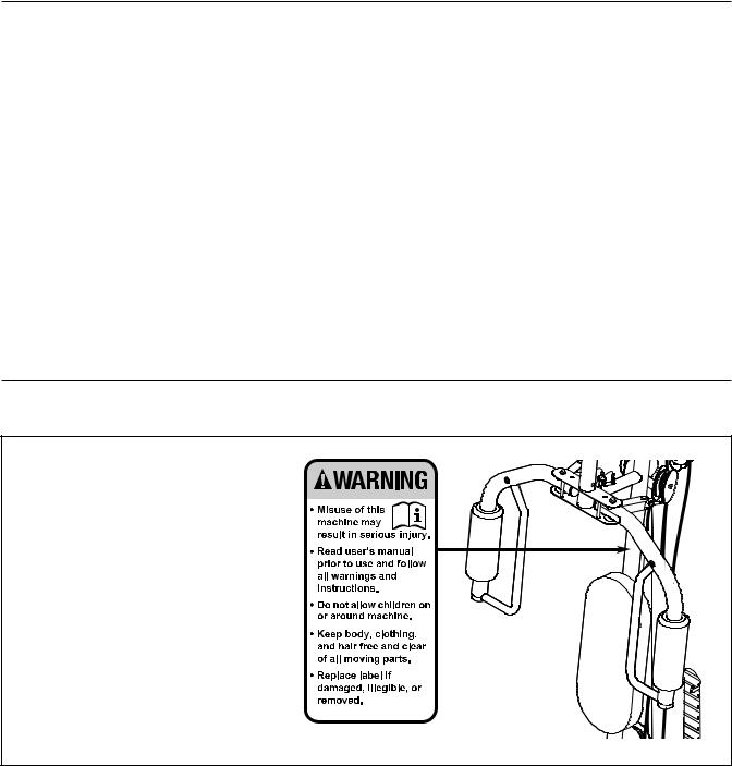
TABLE OF CONTENTS
WARNING DECAL PLACEMENT . . . . . . . . . . . . . . . . . . . . . . . . . . . . . . . . . . . . . . . . . . . . . . . . . . . . . . . . . . . . . .2 IMPORTANT PRECAUTIONS . . . . . . . . . . . . . . . . . . . . . . . . . . . . . . . . . . . . . . . . . . . . . . . . . . . . . . . . . . . . . . . .3 BEFORE YOU BEGIN . . . . . . . . . . . . . . . . . . . . . . . . . . . . . . . . . . . . . . . . . . . . . . . . . . . . . . . . . . . . . . . . . . . . . .5 PART IDENTIFICATION CHART . . . . . . . . . . . . . . . . . . . . . . . . . . . . . . . . . . . . . . . . . . . . . . . . . . . . . . . . . . . . . .6 ASSEMBLY . . . . . . . . . . . . . . . . . . . . . . . . . . . . . . . . . . . . . . . . . . . . . . . . . . . . . . . . . . . . . . . . . . . . . . . . . . . . . . .7 ADJUSTMENT . . . . . . . . . . . . . . . . . . . . . . . . . . . . . . . . . . . . . . . . . . . . . . . . . . . . . . . . . . . . . . . . . . . . . . . . . . .23 WEIGHT RESISTANCE CHART . . . . . . . . . . . . . . . . . . . . . . . . . . . . . . . . . . . . . . . . . . . . . . . . . . . . . . . . . . . . . .25 CABLE DIAGRAMS . . . . . . . . . . . . . . . . . . . . . . . . . . . . . . . . . . . . . . . . . . . . . . . . . . . . . . . . . . . . . . . . . . . . . . .26 MAINTENANCE . . . . . . . . . . . . . . . . . . . . . . . . . . . . . . . . . . . . . . . . . . . . . . . . . . . . . . . . . . . . . . . . . . . . . . . . . .27 EXERCISE GUIDELINES . . . . . . . . . . . . . . . . . . . . . . . . . . . . . . . . . . . . . . . . . . . . . . . . . . . . . . . . . . . . . . . . . . .28 PART LIST . . . . . . . . . . . . . . . . . . . . . . . . . . . . . . . . . . . . . . . . . . . . . . . . . . . . . . . . . . . . . . . . . . . . . . . . . . . . . .29 EXPLODED DRAWING . . . . . . . . . . . . . . . . . . . . . . . . . . . . . . . . . . . . . . . . . . . . . . . . . . . . . . . . . . . . . . . . . . . .30 ORDERING REPLACEMENT PARTS . . . . . . . . . . . . . . . . . . . . . . . . . . . . . . . . . . . . . . . . . . . . . . . . . .Back Cover
WARNING DECAL PLACEMENT
This drawing shows the location(s) of the warning decal(s). If a decal is missing or illegible, see the front cover of this manual and request a free replacement decal. Apply the decal in the location shown.
Note: The decal(s) may not be shown at actual size.
WEIDER is a registered trademark of ICON IP, Inc.
2
IMPORTANT PRECAUTIONS
WARNING: To reduce the risk of serious injury, read all important precautions and ructions in this manual and all warnings on your weight system before using your weight sys-
tem. ICON assumes no responsibility for personal injury or property damage sustained by or through the use of this product.
1. Before beginning any exercise program, consult your physician. This is especially important for persons over age 35 or persons with pre-existing health problems.
2. Read all instructions in this manual and all warnings on the weight system before using the weight system. Use the weight system only as described in this manual.
3.It is the responsibility of the owner to ensure that all users of the weight system are adequately informed of all precautions.
4. The weight system is intended for home use only. Do not use the weight system in any commercial, rental, or institutional setting.
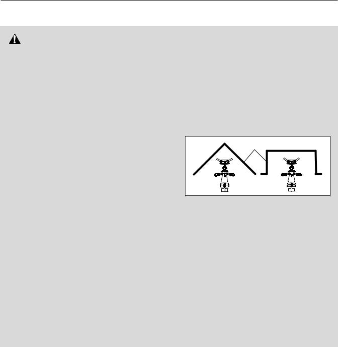
5. Keep the weight system indoors, away from moisture and dust. Do not put the weight system in a garage or covered patio, or near water.
6. Place the weight system on a level surface, with a mat beneath it to protect the floor or carpet. Make sure that there is enough clearance around the weight system to mount, dismount, and use the weight system.
7. This weight system has an open weight stack; the weight stack must not be accessible from any point outside the userʼs field of
3

13.Always secure the weight stack with the lock pin and lock after exercising to prevent unauthorized use of the weight system (see LOCKING THE WEIGHT STACK on page 24).
14.Make sure that the cables remain on the pulleys at all times. If the cables bind as you are exercising, stop immediately and make sure that the cables are on the pulleys.
15.Always stand on the foot plate when performing an exercise that could cause the weight system to tip.
16.Never release the arms, leg lever, lat bar, or ankle strap while weights are raised. The weights will fall with great force.
17.Always disconnect the lat bar from the weight system when performing an exercise that does not require the lat bar.
18.Over exercising may result in serious injury or death. If you feel faint or if you experience pain while exercising, stop immediately and cool down.
4
BEFORE YOU BEGIN
Thank you for selecting the versatile WEIDER® PRO 4500 weight system. The 4500 weight system offers a selection of weight stations designed to develop every major muscle group of the body.
For your benefit, read this manual carefully before using your weight system. If you have questions after reading this manual, please see the front cover of this manual. To help us assist you, note the product
model number and serial number before contacting us. The model number and the location of the serial number decal are shown on the front cover of this manual.
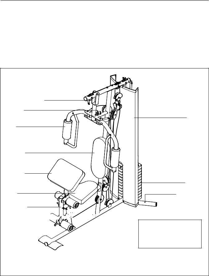
Before reading further, please review the drawing below and familiarize yourself with the parts that are labeled.
High Pulley Station
Arm Pin
Arm
Right Side
Backrest
Curl Pad
Seat
Leg Lever
Low Pulley Station 


Foot Plate 


Shroud |
Left Side |
Weights |
Anchor Hole* |
ASSEMBLED DIMENSIONS: Height: 6 ft. 4 in. (193 cm) Width: 3 ft. 1 in. (94 cm) Depth: 4 ft. (122 cm)
Note: The terms “right side” and “left side” are determined relative to a person sitting on the seat; they do not correspond to right and left on the drawings in this manual. *Use the anchor holes to secure the weight system in a fixed position, if desired.
5

PART IDENTIFICATION CHART
Refer to the drawings below to identify small parts used in assembly. The number in parentheses by each drawing is the key number of the part, from the PART LIST near the end of this manual. Note: If a part is not in the hardware kit, check to see if it has been preattached.
M8 Locknut (58) |
M10 Locknut (56) |
M12 Nut (86) |
|
|
M6 Washer |
M8 Washer (59) |
|
|
(82) |
M10 Washer (57) |
||
|
M10 Large
Washer (80) Large Washer (87)
M10 x 45mm
Bolt (81)
M8 x 19mm |
|
M10 x 40mm |
Shoulder |
|
Bolt (77) |
Bolt (65) |
|
|
M4 x 10mm |
M6 x 16mm |
M4 x 19mm |
Screw (84) |
Screw (62) |
Screw (69) |
M10 x 55mm Bolt (66)
M10 x 65mm Bolt (75)
M8 x 75mm Carriage Bolt (78)
M10 x 75mm Bolt (85)
M6 x 80mm Screw (70)
M8 x 80mm Bolt (68)
M10 x 80mm Bolt (71)
M10 x 80mm 10.9G Bolt (79)
M10 x 70mm Bolt Set (73)
M10 x 90mm Bolt (67)
M10 x 160mm Bolt (74)
6

ASSEMBLY
To make assembly easier, carefully read the following information and instructions:
•Assembly requires two persons.
•Because of its weight and size, the weight system should be assembled in the location where it will be used. Make sure that there is enough clearance to walk around the weight system while you assemble it.
•Place all parts in a cleared area and remove the packing materials. Do not dispose of the packing materials until assembly is completed.
•For help identifying small parts, use the PART IDENTIFICATION CHART on page 6.
•The following tools (not included) may be required for assembly:
two adjustable wrenches one rubber mallet one standard screwdriver one Phillips screwdriver
Assembly may be more convenient if you have a socket set, a set of open-end or closed-end wrenches, or a set of ratchet wrenches.
|
The Four Stages of the Assembly Process |
|
|
|
|
|
|
|
Frame Assembly—You will begin by assem- |
Cable Assembly—During this stage, you will |
|
|
bling the base and the uprights that form the |
attach the cables and pulleys that connect the |
|
|
skeleton of the weight system. |
arms to the weights. |
|
|
Arm Assembly—During this stage, you will |
Seat Assembly—During the final stage, you will |
|
|
assemble the arms and the leg lever. |
assemble the seat and the backrest. |
|
|
|
|
|
7
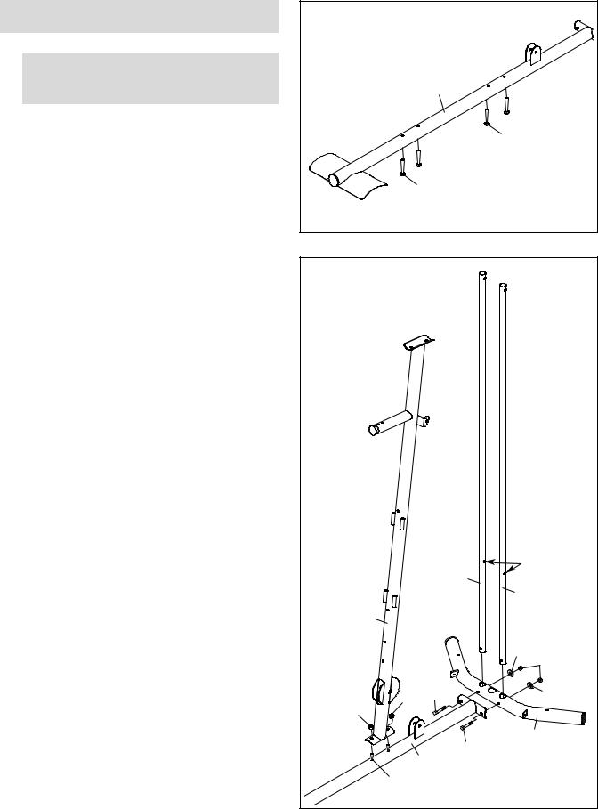
Frame Assembly
1.IMPORTANT:To make assembly easier, read the assembly tips on page 7.
Insert four M8 x 75mm Carriage Bolts (78) up through the Base (1). Note: It may be helpful to place tape over the bolt heads to hold them in place.
2.Orient the two Weight Guides (21) so that the indicated holes are closer to the lower ends. Attach the two Weight Guides and the Base (1) to the Stabilizer (2) with two M10 x 80mm 10.9G Bolts (79), two M10 Washers (57), and two M10 Locknuts (56). Tighten the Locknuts. Attach the Upright (3) to the Base (1) with the two indicated M8 x 75mm Carriage Bolts (78) and two M8 Locknuts (58). Do not tighten the
Locknuts yet.
1 |
1 |
78 |
78 |
2 |
|
|
|
21 |
Holes |
|
|
|
|
21 |
|
|
|
|
|
|
|
|
|
3 |
|
|
|
|
|
|
|
|
57 |
56 |
|
|
|
|
|
|
58 |
58 |
79 |
|
|
57 |
|
|
|
|
|
|
|
|
|
79 |
|
2 |
|
|
1 |
|
|
|
|
|
|
|
|
|
|
78 |
|
|
|
|
8
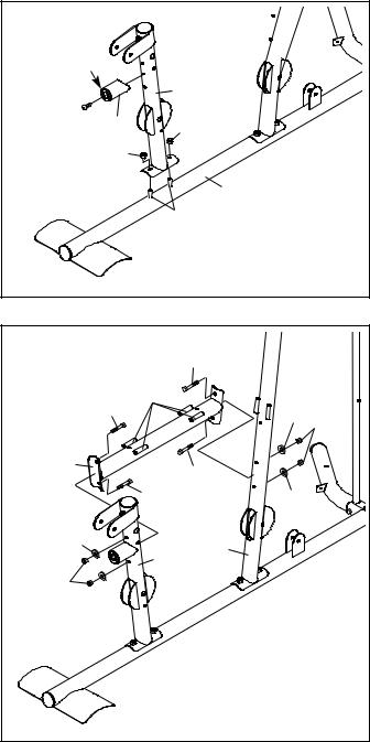
3. Attach the Front Leg (7) to the Base (1) with the |
3 |
|
|
|
|
|
|
|
two indicated M8 x 75mm Carriage Bolts (78) |
|
|
|
|
|
|
|
|
|
|
|
|
|
|
|
|
|
and two M8 Locknuts (58). Do not tighten the |
Up |
|
|
|
|
|
|
|
Locknuts yet. |
|
|
|
|
|
|
|
|
Attach the Leg Bumper (60) to the Front Leg (7) |
|
|
|
|
|
7 |
|
|
with an M4 x 19mm Screw (69). Make sure |
69 |
60 |
|
|
58 |
|
|
|
that the end of the Leg Bumper is pointing |
|
|
|
|
||||
upward. |
|
58 |
|
|
|
|
|
|
|
|
|
|
|
|
|
1 |
|
|
|
|
|
|
78 |
|
|
|
4. Hold the Seat Frame (6) between the Upright |
4 |
|
|
|
|
|
|
|
(3) and the Front Leg (7). Orient the Seat |
|
|
|
|
68 |
|
|
|
|
|
|
|
|
|
|
||
Frame so that the welded rods are closer to the |
|
|
Welded |
|
|
|||
Upright. |
|
|
|
|
|
|||
|
68 |
|
Rods |
|
|
|
|
|
|
|
|
|
|
59 |
|
||
Attach the Seat Frame (6) to the Upright (3) |
|
|
|
|
|
58 |
||
|
|
|
|
|
|
|||
with two M8 x 80mm Bolts (68), two M8 |
|
|
|
|
|
|
|
|
Washers (59), and two M8 Locknuts (58). Do |
6 |
|
|
|
|
|
|
|
not tighten the Locknuts yet. |
|
|
|
|
68 |
|
|
|
|
|
|
68 |
|
|
|
||
Attach the Seat Frame (6) to the Front Leg |
|
|
|
|
|
59 |
|
|
|
|
|
|
|
|
|
|
|
(7) in the same manner. |
59 |
|
|
|
|
|
3 |
|
|
|
|
7 |
|
|
|
||
|
|
|
|
|
|
|
||
|
|
|
|
|
|
|
|
|
|
58 |
59 |
|
|
|
|
|
|
|
|
|
|
|
|
|
|
|
9
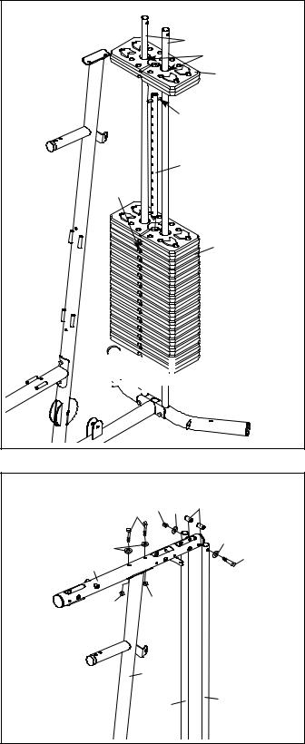
5. Slide the two Weight Bumpers (27) onto the |
5 |
|
|
Weight Guides (21). Orient fourteen Weights |
|
|
|
|
|
|
|
(22) so the pin holes are on the bottom, and |
|
21 |
|
slide the Weights onto the Weight Guides. |
|
Grease |
|
|
|
||
|
|
|
|
Insert the Weight Tube (24) into the fourteen |
|
|
22 |
Weights (22). Make sure that the pin on the |
|
|
|
Weight Tube is oriented as shown. |
|
Pin |
|
|
|
|
|
Using the included grease packet, lubricate the |
|
|
|
indicated holes in a Weight (22). Slide the |
|
24 |
|
Weight onto the Weight Guides (21). |
Pin |
|
|
|
|
|
|
|
Hole |
|
|
|
|
|
22 |


 27
27
6. Attach the Top Frame (4) to the Upright (3) with |
6 |
|
|
|
|
two M8 x 80mm Bolts (68), two M8 Washers |
|
68 56 57 76 |
|
|
|
|
|
|
|
||
(59), and two M8 Locknuts (58). Do not tighten |
|
|
|
|
|
the Locknuts yet. |
|
|
|
57 |
|
Attach the Top Frame (4) between the Weight |
|
59 |
|
74 |
|
4 |
|
|
|||
Guides (21) with an M10 x 160mm Bolt (74), |
|
|
|
||
|
|
|
|
||
two M10 Washers (57), two 13mm Spacers |
|
|
|
|
|
(76), and an M10 Locknut (56). Do not tighten |
|
58 |
58 |
|
|
the Locknuts yet. |
|
|
|
||
|
|
|
3 |
|
|
|
|
|
21 |
21 |
|
|
|
|
|
|
10
 Loading...