


Model No. WESY9975.0
Serial No.
Write the serial number in the space above for future reference. 
Serial Number Decal ( u
u nder seat)
QUESTIONS?
As a manufacturer, we are committed to providing complete customer satisfaction. If you have questions, or if a part is damaged or missing, PLEASE CONTACT OUR CUSTOMER SERVICE DEPARTMENT DIRECTLY.
CALL TOLL-FREE:
1-877-992-5999
Mon.–Fri., 6 a.m.–6 p.m. MST
ON THE WEB:
www.weiderservice.com
 CAUTION
Read all precautions and instructions in this manual before using this equipment. Save this manual for future reference.
USER’S MANUAL

 Visit our website at
www.weiderfitness.com
new products, prizes, fitness tips, and much more!

TABLE OF CONTENTS
WARNING DECAL PLACEMENT . . . . . . . . . . . . . . . . . . . . . . . . . . . . . . . . . . . . . . . . . . . . . . . . . . . . . . . . . . . . . 3 IMPORTANT PRECAUTIONS . . . . . . . . . . . . . . . . . . . . . . . . . . . . . . . . . . . . . . . . . . . . . . . . . . . . . . . . . . . . . . . . 4 BEFORE YOU BEGIN . . . . . . . . . . . . . . . . . . . . . . . . . . . . . . . . . . . . . . . . . . . . . . . . . . . . . . . . . . . . . . . . . . . . . . 5 ASSEMBLY . . . . . . . . . . . . . . . . . . . . . . . . . . . . . . . . . . . . . . . . . . . . . . . . . . . . . . . . . . . . . . . . . . . . . . . . . . . . . . .6 ADJUSTMENTS . . . . . . . . . . . . . . . . . . . . . . . . . . . . . . . . . . . . . . . . . . . . . . . . . . . . . . . . . . . . . . . . . . . . . . . . . . 16 CONSOLE OPERATION . . . . . . . . . . . . . . . . . . . . . . . . . . . . . . . . . . . . . . . . . . . . . . . . . . . . . . . . . . . . . . . . . . . .21 TROUBLESHOOTING . . . . . . . . . . . . . . . . . . . . . . . . . . . . . . . . . . . . . . . . . . . . . . . . . . . . . . . . . . . . . . . . . . . . .23 EXERCISE GUIDELINES . . . . . . . . . . . . . . . . . . . . . . . . . . . . . . . . . . . . . . . . . . . . . . . . . . . . . . . . . . . . . . . . . . 24 ORDERING REPLACEMENT PARTS . . . . . . . . . . . . . . . . . . . . . . . . . . . . . . . . . . . . . . . . . . . . . . . . . .Back Cover LIMITED WARRANTY . . . . . . . . . . . . . . . . . . . . . . . . . . . . . . . . . . . . . . . . . . . . . . . . . . . . . . . . . . . . . . Back Cover
Note: A PART IDENTIFICATION CHART and a PART LIST/EXPLODED DRAWING are attached in the center of this manual. Remove the PART IDENTIFICATION CHART and PART LIST/EXPLODED DRAWING before beginning assembly.
WEIDER is a registered trademark of ICON IP, Inc.
2
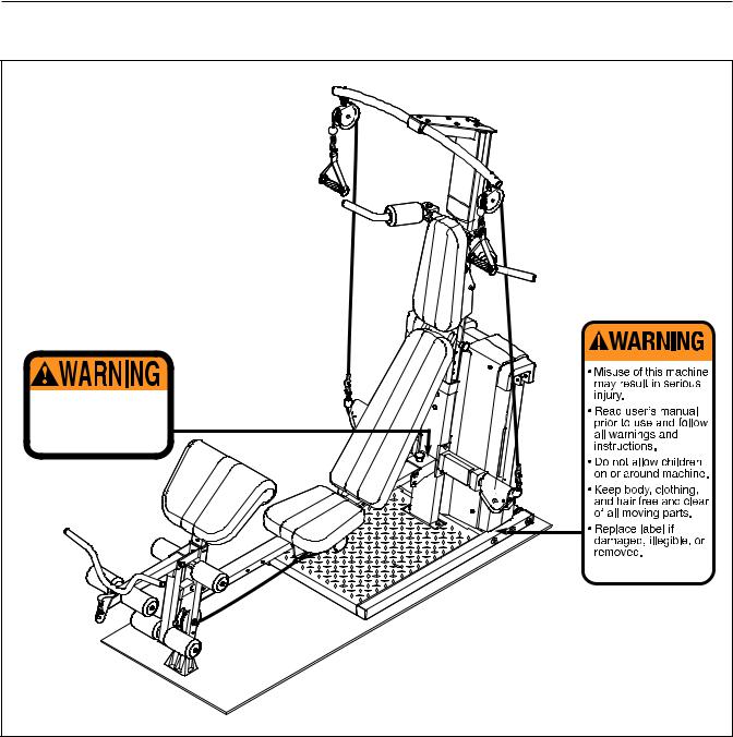
WARNING DECAL PLACEMENT
The decals shown here have been placed on the resistance system. If a decal is missing or illegible, please call the toll-free telephone number on the front cover of this manual and order a free replacement decal. Apply the decal in the location shown.
Keep hands and fingers clear of this area.
3

IMPORTANT PRECAUTIONS
 WARNING: To reduce the risk of serious injury, read the following important precautions before using the resistance system.
1.Read all instructions in this manual and all warnings on the resistance system before using the resistance system. Use the resistance system only as described in this manual.
2.It is the responsibility of the owner to ensure that all users of the resistance system are adequately informed of all precautions.
3.The resistance system is intended for home use only. Do not use the resistance system in any commercial, rental, or institutional setting.
4.Keep the resistance system indoors, away from moisture and dust. Place the resistance system on a level surface, with a mat beneath it to protect the floor or carpet. Make sure that there is enough clearance around the resistance system to mount, dismount, and use the resistance system.
5.Inspect and properly tighten all parts regularly. Replace any worn parts immediately.
6.Keep children under 12 and pets away from the resistance system at all times.
7.Keep hands and feet away from moving parts.
8.Always wear athletic shoes for foot protection while exercising.
9.The resistance system is designed to support a maximum user weight of 300 pounds.
10.The top frame is not designed to be used for pull-up exercises. Do not hang on the top frame.
11.Pull on the lower cable only while sitting on the bench or standing on the base plate. Pull on the high cables only while sitting on the bench, with the seat in one of the three positions closest to the upright base, or while standing on the base plate.
12.The resistance system is designed to be used with the included resistance. Do not use the resistance system with any other type of resistance.
13.Always disconnect the lat bar from the high cables when performing an exercise that does not require it.
14.Make sure the storage knob is in place and fully tightened each time the resistance system is used.
15.Make sure that the cables remain on the pulleys at all times. If the cables bind as you are exercising, stop immediately and make sure that the cables are on the pulleys. Replace all cables at least every two years.
16.Always make sure the two screws in the rope clamps are fully tightened each time the resistance system is used.
17.Do not pull on the cables while the resistance level is being adjusted.
18.If you feel pain or dizziness while exercising, stop immediately and begin cooling down.
 WARNING: Before beginning this or any exercise program, consult your physician. This is especially important for persons over the age of 35 or persons with pre-existing health problems. Read all instructions before using. ICON assumes no responsibility for personal injury or property damage sustained by or through the use of this product.
4
BEFORE YOU BEGIN
Thank you for selecting the innovative PLATINUM PLUS 1000 BY WEIDER® resistance system. The resistance system offers a selection of stations designed to develop every major muscle group of the body. Whether your goal is to tone your body, build dramatic muscle size and strength, or improve your cardiovascular system, the resistance system will help you to achieve the specific results you want.
For your benefit, read this manual carefully before using the resistance system. If you have questions after reading this manual, see the front cover of this
manual. To help us assist you, please note the product model number and serial number before calling. The model number is WESY9975.0. The serial number can be found on a decal attached to the resistance system (see the front cover of this manual).
To avoid a registration fee for any service needed under warranty, you must register the weight system at www.weiderservice.com/registration.
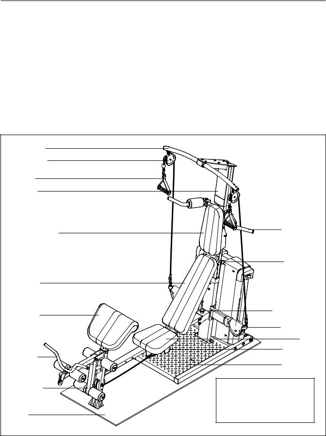
Before reading further, please review the drawing below and familiarize yourself with the parts that are labeled.
Top Frame |
|
|
|
|
High Pulley |
|
|
|
|
Handle |
|
|
|
|
Console |
|
|
|
|
Squat Backrest |
|
|
|
Squat Arm |
|
|
|
|
|
|
|
|
|
Squat Pin |
Backrest |
|
|
|
|
Curl Pad |
|
|
|
Storage Knob |
|
|
|
|
|
|
|
|
|
Low Pulley |
|
|
|
|
Seat |
|
|
|
|
Seat Knob |
Curl Bar |
|
|
|
|
|
|
|
|
Base Plate |
Leg Lever |
ASSEMBLED DIMENSIONS: |
|||
|
Height: |
85 in. |
/ |
216 cm |
|
Width: |
47 in. |
/ |
119 cm |
Mat |
Depth: |
94 in. |
/ |
239 cm |
|
|
|
|
|
|
5 |
|
|
|
ASSEMBLY
Make Things Easier for Yourself
This manual is designed to ensure that the resistance system can be assembled successfully by most people. However, it is important to realize that the versatile resistance system has many parts and that the assembly process will take time. Most people find that by setting aside plenty of time, assembly will go smoothly.
Before beginning assembly, carefully read the following information and instructions:
•Assembly requires two persons.
•Place all parts in a cleared area and remove the packing materials. Do not dispose of the packing materials until assembly is completed.
•For help identifying small parts, use the PART IDENTIFICATION CHART. Note: Some small parts may have been pre-attached for shipping. If a part is not in the parts bag, check to see if it has been pre-attached.
•Tighten all parts as you assemble them, unless instructed to do otherwise.
•As you assemble the resistance system, make sure all parts are oriented as shown in the drawings.
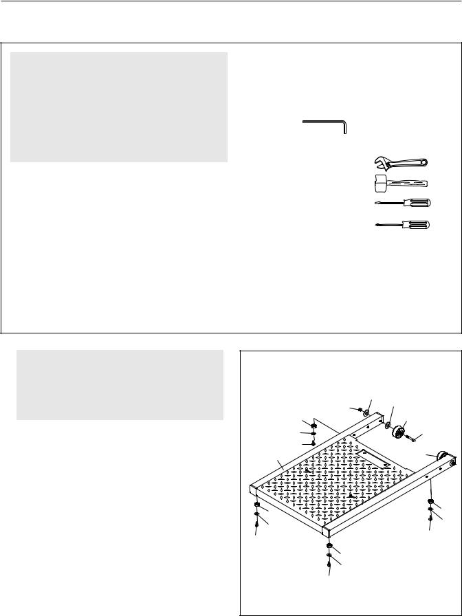
The included hex keys and the following tools (not included) are required for assembly:
• Two adjustable wrenches
• One rubber mallet
• One standard screwdriver
• One Phillips screwdriver
•Lubricant, such as grease or petroleum jelly, tape, and soapy water.
Assembly will be more convenient if you have a socket set, a set of open-end or closed-end wrenches, or a set of ratchet wrenches.
1. |
1 |
|
|
|
Before beginning assembly, make sure that |
|
|
||
|
|
|
||
you have read and understand the informa- |
|
|
|
|
tion in the box above. Refer to the PART |
|
|
|
|
IDENTIFICATION CHART for help identifying |
|
|
152 |
|
small parts. |
|
139 |
152 |
|
71 |
49 |
|||
|
|
|||
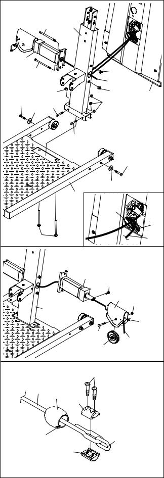
Attach four Plastic Base Feet (71) to the Base (1) |
157 |
|
125 |
|
104 |
|
|
||
with four M4 Washers (157) and four M4 x 16mm |
|
49 |
||
1 |
|
|||
Self-tapping Screws (104). |
|
|||
|
|
|
||
Attach a Wheel (49) to the Base (1) with an M8 x |
|
|
|
|
90mm Shoulder Bolt (125), two M8 Washers |
|
|
|
|
(152), and an M8 Nylon Jamnut (139). Repeat |
|
|
71 |
|
with the other Wheel. |
71 |
|
||
|
157 |
|
157 |
|
|
|
104 |
||
|
104 |
|
||
|
|
|
||
|
|
71 |
|
|
|
|
157 |
|
|
|
|
104 |
|
6
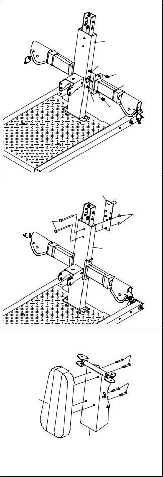
2. Insert two M10 x 65mm Carriage Bolts (103) up |
2 |
|
|
|
through the Base (1). Place a piece of tape over |
|
|
|
|
|
|
|
|
|
the Bolt heads to hold them in place. Connect |
|
107 |
2 |
|
the Upright Base (2) to the Base with the two |
|
|
||
|
|
|
|
|
Carriage Bolts and two M10 Nylon Locknuts |
|
|
|
|
(112). Do not tighten these Locknuts yet. |
|
|
|
|
Connect the Upright Base (2) to the Base (1) with |
171 |
|
|
|
two M10 x 67mm Bolts (111) and two M10 Nylon |
|
107 |
127 |
|
Locknuts (112). Fully tighten these Locknuts. |
|
|
70 |
|
|
|
|
|
|
Set the Mech Frame (124) onto the Base (1) |
|
112 |
127 |
124 |
behind the Upright Base. Handtighten two M10 x |
137 |
|
112 |
|
111 |
|
|||
73mm Bolts (137) and two M10 Washers (129) |
|
|
|
|
|
129 |
|
|
|
into the indicated holes in the Base and Mech |
|
|
|
|
Frame. Note: The Mech Frame will not be |
|
|
|
|
shown in the following drawings for clarity. |
|
|
111 |
|
|
|
|
|
|
Note: One end of the Rope (70) is connected |
|
|
|
|
to the Right Arm Frame (171). Untie the loose |
|
|
|
137 |
end of the Rope and route it through the Upright |
|
|
|
|
|
|
|
|
|
Base (2). Make sure the Rope is still between |
|
|
|
|
the 90mm Thin Pulley (88) and Cable Trap (78) |
|
|
129 |
|
(see the inset drawing), and that the loose end |
|
|
|
|
|
|
1 |
|
|
of the Rope crosses under the connected end |
|
|
|
|
|
|
|
|
|
of the Rope. |
|
|
78 |
|
|
|
|
|
|
Insert two M14 x 155mm Bolts (107) through the |
|
|
|
88 |
Right Arm Frame (171) and the Upright Base (2). |
|
103 |
|
70 |
Hand tighten two M14 Nylon Locknuts (127) onto |
|
|
||
the Bolts. |
3 |
|
|
|
|
|
|
|
|
3. Route the loose end of the Rope (70) through the |
|
|
|
|
Left Arm Frame (8) and a Swivel Arm (29). Make |
|
|
8 |
|
sure the Rope is under the indicated rod in the |
|
|
|
|
|
|
176 |
|
|
Swivel Arm. |
|
|
|
|
|
|
|
|
|
Attach the Swivel Arm (29) to the Left Arm Frame |
|
|
29 |
112 |
|
2 |
|
||
(8) with an M4 x 5mm Self-tapping Screw (176). |
|
|
|
|
Attach a “V”-pulley (93) inside the Swivel Arm |
|
|
|
Rod |
|
|
|
|
|
(29) with an M10 x 53mm Button Bolt (140) and |
|
|
140 |
70 |
an M10 Nylon Locknut (112). |
|
|
93 |
|
|
|
|
||
|
|
|
|
|
4. Route the loose end of the Rope (70) through a |
4 |
|
|
|
Rope Cover (169) and a Link (167) as shown. |
|
164 |
|
|
|
|
|
||
Make sure the large hole in the Rope Cover is |
|
|
|
|
on the side shown. Secure the set of Rope |
|
70 |
|
|
Clamps (165, 166) on the Rope with two M5 x |
|
169 |
|
|
|
|
165 |
|
|
16mm Button Screws (164). Make sure that |
|
|
|
|
|
|
|
|
|
Rope is in the grooves of the Rope Clamps, |
|
|
|
|
that there is 1/2" between the Link and the |
|
|
|
|
Rope Clamps, and that the two Screws are fully |
|
Large |
|
|
tightened. Slide the Rope Cover over the Rope |
|
167 |
|
|
Clamps. |
|
Hole |
166 |
|
|
|
|
|
|
|
7 |
|
|
|
5.Remove the two M14 Nylon Locknuts (127). Attach the Left Arm Frame (8) to the Upright Base
(2) with the two M14 x 155mm Bolts (107) used in step 2 and the two M14 Nylon Locknuts.
6.Attach the Backing Plate (59) to the Upright Base
(2) with two M10 x 65mm Carriage Bolts (103) and two M10 Nylon Locknuts (112). Do not tighten the Locknuts yet.
7.Attach the Squat Backrest (28) to the Squat Carriage (10) with four M6 x 16mm Screws (108).
5 |
|
|
2 |
107 |
|
|
127 |
|
8 |
107 |
127 |
6 |
|
59 |
|
103 |
112 |
|
|
|
2 |
7 |
|
|
108 |
|
108 |
28 |
|
10 |
|
8
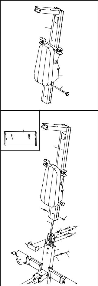
8. Slide the Squat Carriage (10) onto the Upright (3) |
8 |
|
|
as shown. Insert the Squat Pin (35) into an upper |
|
||
|
|
||
hole in the Upright. |
|
|
|
|
3 |
|
|
|
10 |
|
|
|
35 |
|
|
9. Press the Front Cover (31) onto the Upright Base |
9 |
|
|
(2). Make sure the Cover is oriented as shown |
|
||
|
|
||
in the inset drawing. |
31 |
|
|
|
|
||
Route the Upper Wire Harness (172) down |
|
|
|
through the Upright Base (2) and out the large |
|
|
|
round hole in the back, as shown. |
|
|
|
Slide the Upright (3) onto the Upright Base (2). |
3 |
|
|
|
|
||
Make sure you do not pinch the Upper Wire |
|
|
|
Harnesses (172). Secure the Upright with two |
|
|
|
M10 Washers (129), two M10 x 20mm Screws |
|
|
|
(113), and two M10 x 25mm Screws (105). Do |
|
|
|
not tighten the Screws yet. |
|
|
|
Connect the Upper Wire Harness (172) to the |
|
|
|
Lower Wire Harness (173) extending from the |
|
|
|
Mech Frame (not shown). The connector should |
|
|
|
slide easily into the socket and snap into place. |
|
|
|
If the connector does not slide easily and snap into |
159 |
|
|
place, turn it over and then insert it. IF THE CON- |
|
||
159 |
|
||
NECTOR IS NOT INSERTED PROPERLY, THE |
|
||
CONSOLE MAY BE DAMAGED WHEN THE |
172 |
|
|
POWER IS TURNED ON. Press the excess wire |
129 |
113 |
|
into the Upright Base. |
|||
|
105 |
||
|
|
||
Tighten two M4 x 16mm White ZP Self-tapping |
31 |
|
|
Screws (159) into the Upright (3). |
|
||
|
|
||
|
2 |
|
|
|
173 |
|
|
|
172 |
|
9
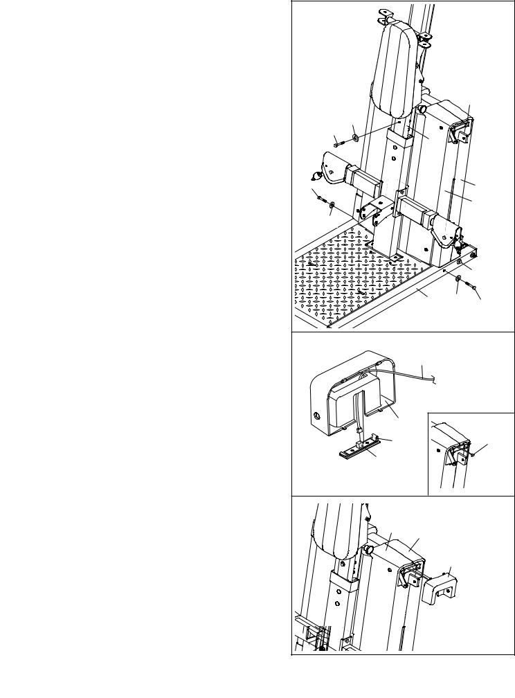
10. |
Insert an M10 x 125mm Button Screw (144) |
10 |
|
|
|
|
through an M10 Washer (129), the Upright (3), |
|
|
|
|
|
|
|
|
|
|
|
and the Backing Plate (not shown). Hold the Bolt |
|
|
|
|
|
in place by sticking a piece of tape over the |
|
|
|
|
|
bolt head. |
|
|
|
|
|
Tighten the two M10 Nylon Locknuts (112) |
|
|
|
|
|
used in step 6. Tighten the two M10 x 20mm |
|
|
|
|
|
Screws (113) and two M10 x 25mm Screws |
|
|
|
124 |
|
(105) used in step 9. |
|
|
|
|
|
|
|
|
|
|
|
Attach the Mech Frame (124) to the Base (1) with |
|
129 |
|
|
|
|
144 |
|
|
|
|
two M10 x 73mm Bolts (137) and two M10 |
|
|
|
|
|
|
3 |
|
|
|
|
Washers (129). Do not tighten the Bolts yet. |
|
|
|
|
|
Attach the Mech Frame (124) to the Upright (3) |
|
|
|
|
|
with the M10 x 125mm Button Screw (144). Make |
137 |
|
|
14 |
|
sure the Upright and Mech Frame are properly |
|
|
||
|
|
|
|
15 |
|
|
aligned before tighten the Screw. |
|
|
|
|
|
Tighten the four M10 x 73mm Bolts (137) in |
|
129 |
|
|
|
|
|
|
|
|
|
the Base (1) and the two M10 Nylon Locknuts |
|
|
|
|
|
(112) used in the first paragraph of step 2. |
|
|
|
|
|
|
|
|
|
137 |
|
|
|
1 |
129 |
137 |
|
|
|
|
|
|
11. |
Locate the Lower Wire Harness (173) (see the |
11 |
|
|
|
|
inset drawing). Connect the Lower Wire Harness |
|
|
|
|
|
|
|
|
|
|
|
to the Sensor (196). The connector should slide |
|
173 |
|
|
|
easily into the socket and snap into place. If the |
|
|
|
|
|
connector does not slide easily and snap into place, |
|
|
|
|
|
turn the connector over and then insert it. IF THE |
|
|
|
|
|
CONNECTOR IS NOT INSERTED PROPERLY, |
|
|
|
|
|
THE CONSOLE MAY BE DAMAGED WHEN |
|
81 |
|
|
|
THE POWER IS TURNED ON. |
|
|
|
|
|
Snap the Sensor Plate (183) into the Side Mech |
|
183 |
|
173 |
|
|
|
|
|
|
|
Cover (81). |
|
196 |
|
|
|
|
|
|
|
|
12. |
Snap the Side Mech Cover (81) into place on the |
12 |
|
|
|
|
Mech Covers (14 and 15). |
|
|
|
|
|
|
|
|
|
|
|
|
|
15 |
|
|
|
|
|
14 |
|
|
|
|
|
|
81 |
|
|
|
10 |
|
|
|
13.Wet a Squat Arm (18) and the inside of a Small Foam Pad (36) with soapy water. Slide the Foam Pad onto the Squat Arm.
Grease an M10 x 73mm Bolt (137). Attach a Squat Arm (18) to the Squat Carriage (10) with the Bolt, two 24mm Plastic Washers (110), and an M10 Nylon Locknut (112). Do not overtighten the Locknut; the Squat Arm should be able to pivot with intermediate effort.
Repeat this step with the other Squat Arm
14.Orient the Top Frame (20) with the mark in the position shown. Attach the Top Frame to the Upright (3) with two M10 x 65mm Button Screws
(117)and two M10 Washers (129). Press the Plastic Cap (46) into the Upright, over the Top Frame.
15.Attach the Upright Plate (23) to the Upright (3) with six M4 x 9mm Self-tapping Screws (106).
16.Attach the Console (21) to the Upper Wire Harness (172). The connector should slide easily into the socket and snap into place. If a connector does not slide easily and snap into place, turn it over and then insert it. IF THE CONNEC-
TOR IS NOT INSERTED PROPERLY, THE CONSOLE MAY BE DAMAGED WHEN THE POWER IS TURNED ON. Push the excess wire into the Upright (3).
Attach the Console (21) to the Upright (3) with two M4 x 80mm Self-tapping Screws (145), two M4 x 65mm Self-tapping Screws (158), and four M4 Washers (157).
13 |
|
137 |
|
|
|
|
|
Grease |
|
36 |
110 |
|
10 |
|
18 |
|
|
|
|
110 |
|
|
18 |
|
|
112 |
14 |
|
|
|
20 |
Mark |
|
|
|
|
|
3 |
46 |
117 |
129 |
|
|
|
15 |
|
106 |
|
|
|
|
|
106 |
|
|
23 |
|
|
3 |
16 |
|
|
|
|
158 |
|
|
157 |
21 |
|
172 |
|
|
145 |
|
|
3 |
|
|
157 |
11
 Loading...