


Model No. WESY78730 Serial No.
Write the serial number in the space above for future reference.
 Serial Number Decal (under seat)
QUESTIONS?
As a manufacturer, we are committed to providing complete customer satisfaction. If you have questions, or if there are missing or damaged parts, we will guarantee complete satisfaction through direct assistance from our factory.
TO AVOID DELAYS, PLEASE CALL DIRECT TO OUR TOLLFREE CUSTOMER HOT LINE.
The trained technicians on our customer hot line will provide immediate assistance, free of charge. 1CUSTOMER-800-999HOT-LINE:3756 Mon.–Fri., 6 a.m.–6 p.m. MST
CAUTION
Read all precautions and instructions in this manual before using this equipment. Save this manual for future reference.
USERʼS MANUAL


 Visit our website at www.TheCrossBow.com
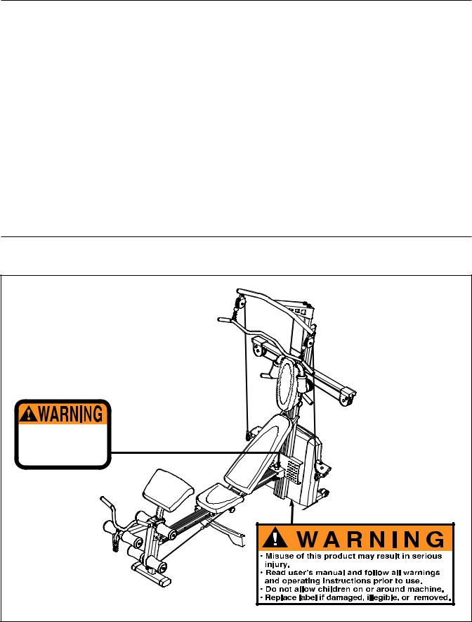
TABLE OF CONTENTS
WARNING DECAL PLACEMENT . . . . . . . . . . . . . . . . . . . . . . . . . . . . . . . . . . . . . . . . . . . . . . . . . . . . . . . . . . . . . 2 IMPORTANT PRECAUTIONS . . . . . . . . . . . . . . . . . . . . . . . . . . . . . . . . . . . . . . . . . . . . . . . . . . . . . . . . . . . . . . . . 3 BEFORE YOU BEGIN . . . . . . . . . . . . . . . . . . . . . . . . . . . . . . . . . . . . . . . . . . . . . . . . . . . . . . . . . . . . . . . . . . . . . . 4 ASSEMBLY . . . . . . . . . . . . . . . . . . . . . . . . . . . . . . . . . . . . . . . . . . . . . . . . . . . . . . . . . . . . . . . . . . . . . . . . . . . . . . .5 ADJUSTMENTS . . . . . . . . . . . . . . . . . . . . . . . . . . . . . . . . . . . . . . . . . . . . . . . . . . . . . . . . . . . . . . . . . . . . . . . . . . 14 CONSOLE OPERATION . . . . . . . . . . . . . . . . . . . . . . . . . . . . . . . . . . . . . . . . . . . . . . . . . . . . . . . . . . . . . . . . . . . .18 CABLE DIAGRAM . . . . . . . . . . . . . . . . . . . . . . . . . . . . . . . . . . . . . . . . . . . . . . . . . . . . . . . . . . . . . . . . . . . . . . . . .20 TROUBLESHOOTING . . . . . . . . . . . . . . . . . . . . . . . . . . . . . . . . . . . . . . . . . . . . . . . . . . . . . . . . . . . . . . . . . . . . .21 EXERCISE GUIDELINES . . . . . . . . . . . . . . . . . . . . . . . . . . . . . . . . . . . . . . . . . . . . . . . . . . . . . . . . . . . . . . . . . . 22 PART IDENTIFICATION CHART . . . . . . . . . . . . . . . . . . . . . . . . . . . . . . . . . . . . . . . . . . . . . . . . . . . .End of Manual PART LIST . . . . . . . . . . . . . . . . . . . . . . . . . . . . . . . . . . . . . . . . . . . . . . . . . . . . . . . . . . . . . . . . . . . . .End of Manual EXPLODED DRAWING . . . . . . . . . . . . . . . . . . . . . . . . . . . . . . . . . . . . . . . . . . . . . . . . . . . . . . . . . . .End of Manual ORDERING REPLACEMENT PARTS . . . . . . . . . . . . . . . . . . . . . . . . . . . . . . . . . . . . . . . . . . . . . . . . . .Back Cover LIMITED WARRANTY . . . . . . . . . . . . . . . . . . . . . . . . . . . . . . . . . . . . . . . . . . . . . . . . . . . . . . . . . . . . . . Back Cover
WARNING DECAL PLACEMENT
The decals shown here have been placed on the resistance system. If a decal is missing or illegible, please call our Customer Service Department tollfree at 1-800-999-3756, Monday through Friday, 6 a.m. until 6 p.m. Mountain Time, to order a free replacement decal. Apply the decal in the location shown.
fingers clear of this area.
CrossBow by WEIDER is a trademark of ICON Health & Fitness, Inc.
2

IMPORTANT PRECAUTIONS
WARNING: To reduce the risk of serious injury, read the following important precautions ore using the resistance system.
1. Read all instructions in this manual before using the resistance system. Use the resistance system only as described in this manual.
2. It is the responsibility of the owner to ensure that all users of the resistance system are adequately informed of all precautions.
3. The resistance system is intended for home use only. Do not use the resistance system in any commercial, rental, or institutional setting.
4. Use the resistance system only on a level surface. Cover the floor beneath the resistance system to protect the floor.
5. Make sure that all parts are properly tightened each time the resistance system is used. Replace any worn parts immediately.
6. Keep children under 12 and pets away from the resistance system at all times.
7. Keep hands and feet away from moving parts.
8. Always wear athletic shoes for foot protection while exercising.
9. The resistance system is designed to support a maximum user weight of 300 pounds.
10. The crossbar on the top frame is not designed to be used for pull-up exercises. Do not hang on the crossbar.
WARNING: Before beginning this or any exercise program, consult your physician. This specially important for persons over the age of 35 or persons with pre-existing health problems.
Read all instructions before using. ICON assumes no responsibility for personal injury or property damage sustained by or through the use of this product.
3
BEFORE YOU BEGIN
Thank you for selecting the innovative CrossBow by WEIDER™ PLATINUM resistance system. The resistance system offers a selection of stations designed to develop every major muscle group of the body. Whether your goal is to tone your body, build dramatic muscle size and strength, or improve your cardiovascular system, the resistance system will help you to achieve the specific results you want.
For your benefit, read this manual carefully before using the resistance system. If you have questions
after reading this manual, please call our Customer Service Department toll-free at 1-800-999-3756, Monday through Friday, 6 a.m. until 6 p.m. Mountain Time (excluding holidays). To help us assist you, please note the product model number and serial number before calling. The model number is WESY78730. The serial number can be found on a decal attached to the resistance system (see the front cover of this manual).
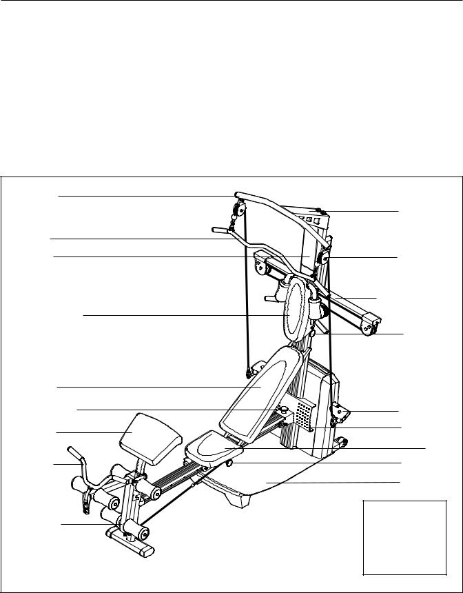
Before reading further, please review the drawing below and familiarize yourself with the parts that are labeled.
Crossbar |
|
|
|
Top Frame |
|
Lat Bar |
|
|
Console |
High Pulley |
|
|
Resistance Bow |
|
Squat Backrest |
|
|
|
|
Squat Pin |
Backrest |
|
|
Storage Knob |
Low Pulley |
|
Curl Pad |
|
Row Plate |
|
|
|
|
|
Seat |
Curl Bar |
|
Seat Knob |
|
Base Plate |
|
Leg Lever |
ASSEMBLED |
|
DIMENSIONS: |
||
|
Height: |
82 in. |
|
Width: |
66 in. |
|
Depth: |
80 in. |
|
4 |
|
ASSEMBLY
Make Things Easier for Yourself
This manual is designed to ensure that the resistance system can be assembled successfully by most people. However, it is important to realize that the versatile resistance system has many parts and that the assembly process will take time. Most people find that by setting aside plenty of time, assembly will go smoothly.
Before beginning assembly, carefully read the following information and instructions:
•Assembly requires two persons.
•Place all parts in a cleared area and remove the packing materials. Do not dispose of the packing materials until assembly is completed.
•For help identifying small parts, use the PART IDENTIFICATION CHART. Note: Some small parts may have been pre-attached for shipping. If a part is not in the parts bag, check to see if it has been pre-attached.
• |
Tighten all parts as you assemble them, unless |
|
|
instructed to do otherwise. |
|
• |
As you assemble the resistance system, make |
|
|
sure all parts are oriented as shown in the draw- |
|
|
ings. |
|
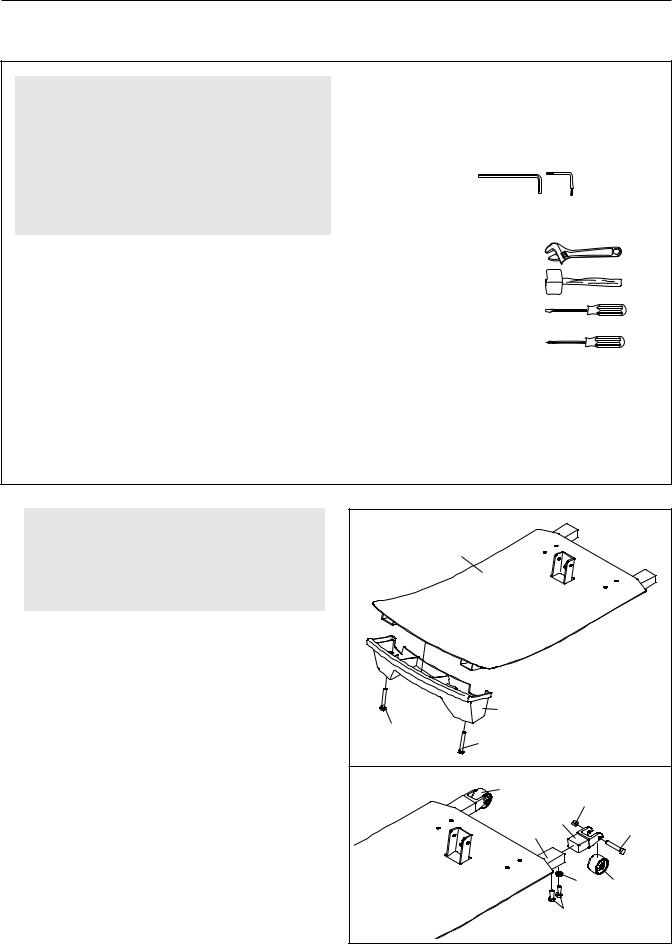
The included Allen wrenches |
and the fol- |
|
lowing tools (not included) are required for |
||
assembly: |
|
|
• |
Two adjustable wrenches |
|
• |
One rubber mallet |
|
• |
One standard screwdriver |
|
• |
One Phillips screwdriver |
|
• |
Lubricant, such as grease or petroleum jelly, |
|
|
and soapy water. |
|
Assembly will be more convenient if you have a socket set, a set of open-end or closed-end wrenches, or a set of ratchet wrenches.
1. |
Before beginning assembly, make sure that |
1 |
|
|
|
|
|
|
|
|
|
|
|
|
|
||
|
you have read and understand the informa- |
|
|
1 |
|
|
|
|
|
tion in the box above. Refer to the PART |
|
|
|
|
|
|
|
|
IDENTIFICATION CHART for help identifying |
|
|
|
|
|
|
|
|
small parts. |
|
|
|
|
|
|
|
|
Attach the Base Plate Foot (63) to the Base Plate |
|
|
|
|
|
|
|
|
(1) with two M4 x 38mm Screws (100). |
|
|
|
|
|
|
|
|
|
|
100 |
63 |
|
|
|
|
|
|
|
100 |
|
|
|
|
|
|
|
|
|
|
|
|
|
|
2. Attach a Wheel (65) to a Wheel Insert (64) with an |
2 |
|
65 |
|
|
|
|
|
|
M10 x 78mm Button Bolt (99) and an M10 Nylon |
|
|
|
103 |
|
||
|
|
|
|
|
|
|||
|
Locknut (103). Do not overtighten the Locknut; |
|
|
|
|
|
|
|
|
|
|
|
|
64 |
|
|
|
|
the Wheel must be able to turn easily. |
|
|
|
1 |
|
99 |
|
|
|
|
|
|
|
|
||
|
Attach the Wheel Insert (64) to the Base Plate (1) |
|
|
|
|
|
|
|
|
with two M4 x 16mm Screws (118) and a Plastic |
|
|
|
|
|
36 |
65 |
|
Foot (36). |
|
|
|
|
|
||
|
Attach the other Wheel (65) in the same man- |
|
|
|
|
118 |
|
|
|
ner. |
|
|
|
|
|
|
|
|
|
5 |
|
|
|
|
|
|
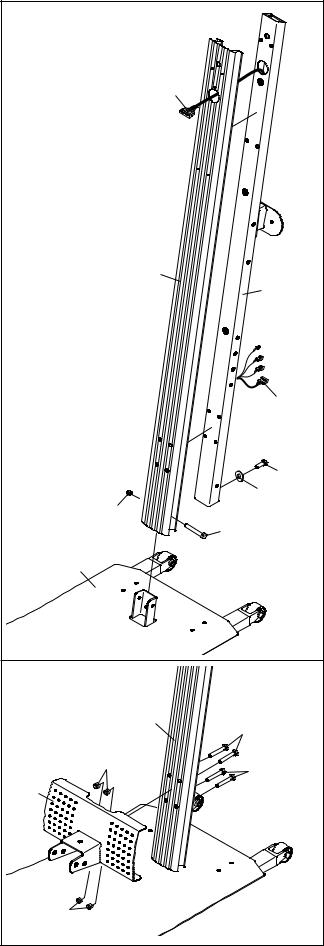
3. Insert the Upper Wire Harness (71) through the |
3 |
|
|
|
hole in the Upright Cover (3). Pull the lower end |
|
|
|
|
|
|
|
|
|
of the Upper Wire Harness out of the hole in the |
|
|
|
|
back of the Upright (2). |
|
|
|
|
Attach the Upright Cover (3) and Upright (2) to |
|
|
|
71 |
the Base Plate (1) with an M10 x 25mm Button |
|
|
|
|
Screw (88), an M10 Washer (106), an M10 x |
|
|
|
|
92mm Button Bolt (83), and an M10 Nylon |
|
|
|
|
Locknut (103). |
|
|
|
|
|
|
|
3 |
2 |
|
|
|
|
|
|
|
|
|
71 |
|
|
103 |
|
10688 |
|
|
|
83 |
|
|
|
|
|
|
|
|
1 |
|
|
4. Attach the Row Plate (28) to the Upright (2) with |
4 |
|
|
|
four M10 x 75mm Button Bolts (84) and four M10 |
|
|
|
|
|
|
|
|
|
Nylon Locknuts (103). |
|
|
2 |
|
|
|
|
84 |
|
|
|
|
|
|
|
|
103 |
|
84 |
|
28 |
|
|
|
|
|
|
|
|
|
|
103 |
|
|
|
6 |
|
|
|
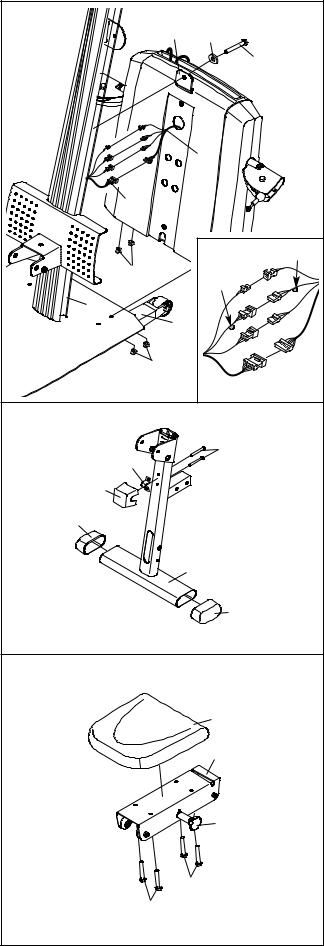
5. Insert the four connectors of the lower wire har- |
5 |
|
|
|
ness (C) into the sockets of the Upper Wire |
|
6 |
12 |
|
|
|
|||
Harness (71). The connectorsshould slide easi- |
|
|
||
ly into the sockets and snap into place. If a con- |
|
|
|
85 |
nector does not slide easily and snap into place, |
|
|
|
|
|
|
|
|
|
turn the connector over and then insert it. |
|
|
|
|
Make sure that the connectors and wires appear |
|
|
|
|
as shown in the inset drawing. IF THE CONNEC- |
|
|
|
|
TORS ARE NOT INSERTED PROPERLY, THE |
|
|
|
C |
CONSOLE MAY BE DAMAGED WHEN THE |
|
|
|
|
POWER IS TURNED ON. |
|
|
|
|
Pull the excess lower wire harness (C) out of |
|
|
71 |
|
|
|
|
|
|
the Mech Frame (6) and push it and the Upper |
|
|
|
Tag |
Wire Harness (71) into the Upright (2). Insert |
|
|
|
|
the Mech Frame into the Base Plate (1). |
|
|
103 |
Tag |
|
|
|
||
Attach the Mech Frame (6) to the Upright (2) with |
|
|
|
|
|
2 |
|
|
|
a 1/2” x 25mm Screw (85) and a 1/2” Lock |
|
1 |
|
|
Washer (12). Do not tighten the Screw yet. |
|
|
|
|
Attach the Mech Frame (6) to the Base Plate (1) |
|
|
103 |
|
with four M10 Nylon Locknuts (103). |
|
|
|
|
|
|
|
|
|
Tighten the 1/2” x 25mm Screw (85). |
6 |
|
|
|
|
|
|
|
|
6. Press two Leg Outer Caps (62) onto the Leg (5). |
|
|
|
108 |
|
|
|
109 |
|
Attach the Leg Bracket (109) and the Leg Lever |
|
|
|
|
|
55 |
|
|
|
Bumper (55) to the Leg (5) with two M5 x 56mm |
|
|
|
|
Screws (108). |
|
62 |
|
|
|
|
|
|
|
|
|
|
|
5 |
|
|
|
|
62 |
7. Pull the Seat Knob (48) and remove the Seat |
7 |
|
|
|
Carriage (44) from the Rail (not shown). |
|
|
|
|
|
|
|
|
|
Attach the Seat (45) to the Seat Carriage (44) |
|
|
|
45 |
with four M6 x 16mm Screws (41). |
|
|
|
|
|
|
|
|
|
|
|
|
|
44 |
|
|
|
|
40 |
|
|
|
|
41 |
|
|
|
41 |
|
|
7 |
|
|
|
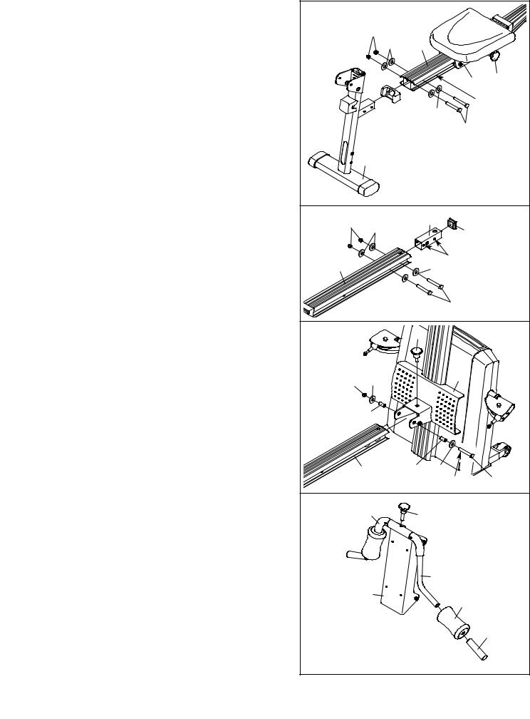
8. |
Pull the Seat Knob (48) out and slide the Seat |
8 |
|
|
|
|
|
|
|
|
Carriage (44) onto the Rail (4) as shown. Engage |
|
|
|
|
|
|
|
|
|
|
|
|
|
|
|
|
|
|
|
the Knob into a hole in the Rail. |
|
|
103106 |
|
|
|
|
|
|
Press the Rail Cap (49) onto the Leg (5). Attach |
|
|
|
4 |
|
|
|
|
|
the Leg to the Rail (4) with two M10 x 64mm |
|
|
|
|
|
|
|
|
|
Button Bolts (80), four M10 Washers (106), and |
|
|
|
|
|
44 |
48 |
|
|
two M10 Nylon Locknuts (103). |
|
|
|
|
|
|||
|
|
|
|
|
|
106 |
|
Holes on |
|
|
|
|
|
49 |
|
|
this side |
||
|
|
|
|
|
|
80 |
|
|
|
|
|
|
|
|
|
|
|
|
|
|
|
|
|
5 |
|
|
|
|
|
9. |
Press a 45mm Square Inner Cap (110) into the |
9 |
|
|
|
31 |
|
|
|
|
Rail Insert (31). |
103 |
106 |
|
|
|
|
||
|
|
|
110 |
|
|||||
|
|
|
|
|
|||||
|
Attach the Rail Insert (31) inside of the Rail (4) |
|
|
|
|
|
|
||
|
|
|
|
|
|
|
|
|
|
|
with two M10 x 64mm Button Bolts (80), four M10 |
|
4 |
|
|
106 Holes |
|
|
|
|
Washers (106), and two M10 Nylon Locknuts |
|
|
|
|
|
|||
|
(103). Make sure the Bolts go through the indi- |
|
|
|
|
|
|
|
|
|
cated holes in the Rail Insert. |
|
|
106 |
|
80 |
|
|
|
|
|
|
|
|
|
|
|||
|
|
|
|
|
|
|
|
|
|
10. |
Lubricate an M10 x 125mm Button Bolt (89) with |
10 |
|
|
29 |
|
|
|
|
|
grease. Attach the Rail (4) to the Row Plate (28) |
|
|
|
|
|
|||
|
|
|
|
|
|
|
|||
|
with the Bolt, two M10 Washers (106), two 31mm |
|
|
|
|
|
|
|
|
|
Spacers (30), and an M10 Nylon Locknut (103). |
|
|
|
|
|
28 |
|
|
|
Do not overtighten the Locknut; the Rail must |
|
103 |
106 |
|
|
|
|
|
|
be able to pivot easily. |
|
|
|
|
|
|
||
|
Tighten the Storage Knob (29) into the Row Plate |
|
|
30 |
|
|
|
|
|
|
(28) and the Rail (4). |
|
|
|
|
|
|
|
|
|
|
|
|
4 |
30 |
106 |
|
|
89 |
|
|
|
|
|
|
Lubricate |
|
||
11. |
Wet a Squat Arm (20) with soapy water. Slide a |
11 |
|
|
|
|
|
|
|
|
Small Foam Pad (24) and a Short Handgrip (21) |
|
20 |
|
27 |
|
|
|
|
|
|
|
|
|
|
|
|||
|
onto the Squat Arm. |
|
|
|
|
|
|
||
|
|
|
|
|
|
|
|
|
|
|
Repeat with the other Squat Arm (20). |
|
|
|
|
|
|
|
|
|
Tighten the Squat Knob (27) into the Squat |
|
|
|
|
20 |
|
|
|
|
Carriage (19) and the Squat Arm Pivot Tube (not |
|
|
|
|
|
|
|
|
|
shown). |
|
|
19 |
|
|
24 |
|
|
|
|
|
|
|
|
|
|
||
|
|
|
|
|
|
|
|
|
|
|
|
|
|
|
|
|
|
|
21 |
|
|
8 |
|
|
|
|
|
|
|
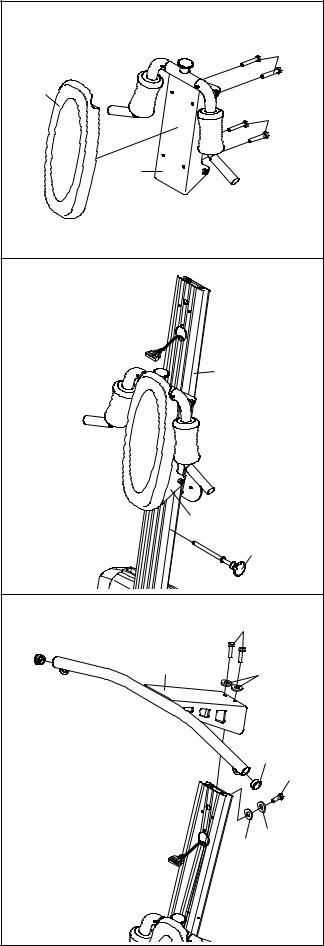
12.Attach the Squat Backrest (25) to the Squat Carriage (19) with four M6 x 16mm Screws (41).
13.Insert the Squat Pin (66) into the Upright (2). Slide the Squat Carriage (19) onto the Upright (2).
14.Press two 38mm Round Inner Caps (38) into the Top Frame (37).
Attach the Top Frame (37) to the Upright (2) with two M10 x 25mm Button Screws (88), an M10 x 75mm Button Screw (84), three M10 Lock Washers (75), and an M10 Washer (106).
12 |
|
|
|
|
|
|
|
|
|
|
41 |
|
25 |
|
|
|
|
|
|
|
|
41 |
|
|
|
19 |
|
|
|
13 |
|
|
|
|
|
|
|
|
2 |
|
|
|
|
19 |
|
|
|
|
|
|
66 |
|
|
14 |
|
|
88 |
|
|
|
|
|
|
|
|
|
38 |
37 |
|
75 |
|
|
|
|
|
|
|
|
|
|
|
38 |
84 |
|
|
|
106 |
75 |
|
9 |
|
|
|
|
|
 Loading...