


Model No. WESY96480
Serial No.
Write the serial number in the space above for reference.
Serial Number Decal (Under Seat)
QUESTIONS?
As a manufacturer, we are committed to providing complete customer satisfaction. If you have questions, or find that there are missing or damaged parts, we will guarantee you complete satisfaction through direct assistance from our factory.
TO AVOID UNNECESSARY DELAYS, PLEASE CALL DIRECT TO OUR TOLL-FREE CUSTOMER HOT LINE. The trained technicians on our customer hot line will provide immediate assistance, free of charge to you.
CUSTOMER HOT LINE:
1-800-999-3756
Mon.–Fri., 6 a.m.–6 p.m. MST
CAUTION
Read all precautions and instructions in this manual before using this equipment. Save this manual for future reference.
USER’S MANUAL
PATENT PENDING

TABLE OF CONTENTS
LIMITED WARRANTY . . . . . . . . . . . . . . . . . . . . . . . . . . . . . . . . . . . . . . . . . . . . . . . . . . . . . . . . . . . . . . . . . . .2 IMPORTANT PRECAUTIONS . . . . . . . . . . . . . . . . . . . . . . . . . . . . . . . . . . . . . . . . . . . . . . . . . . . . . . . . . . . . .3 BEFORE YOU BEGIN . . . . . . . . . . . . . . . . . . . . . . . . . . . . . . . . . . . . . . . . . . . . . . . . . . . . . . . . . . . . . . . . . . .4 ASSEMBLY . . . . . . . . . . . . . . . . . . . . . . . . . . . . . . . . . . . . . . . . . . . . . . . . . . . . . . . . . . . . . . . . . . . . . . . . . . .5 HOW TO USE THE HOME GYM SYSTEM . . . . . . . . . . . . . . . . . . . . . . . . . . . . . . . . . . . . . . . . . . . . . . . . . . .22 WEIGHT RESISTANCE CHART . . . . . . . . . . . . . . . . . . . . . . . . . . . . . . . . . . . . . . . . . . . . . . . . . . . . . . . . . . .24 TROUBLE-SHOOTING AND MAINTENANCE . . . . . . . . . . . . . . . . . . . . . . . . . . . . . . . . . . . . . . . . . . . . . . . .25 CABLE DIAGRAMS . . . . . . . . . . . . . . . . . . . . . . . . . . . . . . . . . . . . . . . . . . . . . . . . . . . . . . . . . . . . . . . . . . . .26 ORDERING REPLACEMENT PARTS . . . . . . . . . . . . . . . . . . . . . . . . . . . . . . . . . . . . . . . . . . . . . . . .Back Cover
Note: A PART IDENTIFICATION CHART and a PART LIST/EXPLODED DRAWING are attached to the center of this manual. Remove the PART IDENTIFICATION CHART and the PART LIST/EXPLODED DRAWING before beginning assembly.
WEIDER is a registered trademark of ICON Health & Fitness, Inc.
LIMITED WARRANTY
ICON Health & Fitness, Inc. (ICON), warrants this product to be free from defects in workmanship and material, under normal use and service conditions, for a period of ninety (90) days from the date of purchase. This warranty extends only to the original purchaser. ICON's obligation under this warranty is limited to replacing or repairing, at ICON's option, the product at one of its authorized service centers. All products for which warranty claim is made must be received by ICON at one of its authorized service centers with all freight and other transportation charges prepaid, accompanied by sufficient proof of purchase. All returns must be pre-authorized by ICON. This warranty does not extend to any product or damage to a product caused by or attributable to freight damage, abuse, misuse, improper or abnormal usage or repairs not provided by an ICON authorized service center, products used for commercial or rental purposes, or products used as store display models. No other warranty beyond that specifically set forth above is authorized by ICON.
ICON is not responsible or liable for indirect, special or consequential damages arising out of or in connection with the use or performance of the product or damages with respect to any economic loss, loss of property, loss of revenues or profits, loss of enjoyment or use, costs of removal, installation or other consequential damages of whatsoever nature. Some states do not allow the exclusion or limitation of incidental or consequential damages. Accordingly, the above limitation may not apply to you.
The warranty extended hereunder is in lieu of any and all other warranties and any implied warranties of merchantability or fitness for a particular purpose is limited in its scope and duration to the terms set forth herein. Some states do not allow limitations on how long an implied warranty lasts. Accordingly, the above limitation may not apply to you.
This warranty gives you specific legal rights. You may also have other rights which vary from state to state.
ICON HEALTH & FITNESS, INC., 1500 S. 1000 W., LOGAN, UT 84321-9813
2

IMPORTANT PRECAUTIONS
WARNING: To reduce the risk of serious injury, read the following important precautions before using the home gym system.
1.It is the responsibility of the owner to ensure that all users of the home gym system are adequately informed of all precautions.
2.The home gym system is intended for home use only. do not use the home gym system in an commercial, rental, or institutional setting.
3.Read all instructions in this manual and in the accompanying literature before using the home gym system.
4.Use the home gym system only on a level surface. Cover the floor beneath the home gym system for protection.
5.Inspect and tighten all parts often. Replace any worn parts immediately.
6.Keep small children and pets away from the home gym system at all times.
7.Never release the press arm, butterfly arms, military press arm, leg lever, leg press plate, lat bar or nylon strap while weights are raised. The weights will fall with great force.
8.Keep hands and feet away from moving parts.
9.Do not use the VKR station when either weight stack is in use.
10.Always wear athletic shoes for foot protection.
11.Always stand on a foot plate when performing an exercise that could cause the home gym system to tip.
12.Keep your hands away from the leg press upright when the military press arm is being used. Your hand could become pinched between the leg press upright and military press arm.
13.Make sure that the cables remain on the pulleys at all times. If the cables bind while you are exercising, stop immediately and make sure that the cables are on all of the pulleys.
14.Always disconnect the lat bar from the home gym system when performing an exercise that does not use the lat bar.
15.If you feel pain or dizziness at any time while exercising, stop immediately and begin cooling down.
WARNING: Before beginning this or any exercise program, consult your physician. This is especially important for persons over the age of 35 or persons with pre-existing health problems. Read all instructions before using. ICON assumes no responsibility for personal injury or property damage sustained by or through the use of this product.
3
BEFORE YOU BEGIN
Thank you for selecting the versatile WEIDER® PRO 9648 Home Gym System. The PRO 9648 offers a selection of weight stations designed to develop every major muscle group of the body. Whether your goal is to tone your body, build dramatic muscle size and strength, or improve your cardiovascular system, the PRO 9648 will help you to achieve the specific results you want.
For your benefit, read this manual carefully before using the WEIDER® PRO 9648 Home Gym System.
If you have additional questions, please call our
Customer Service Department toll-free at 1-800-999- 3756, Monday through Friday, 6 a.m. until 6 p.m. Mountain Time (excluding holidays). To help us assist you, please note the product model number and serial number before calling. The model number is WESY96480. The serial number can be found on a decal attached to the WEIDER® PRO 9648 (see the front cover of this manual).
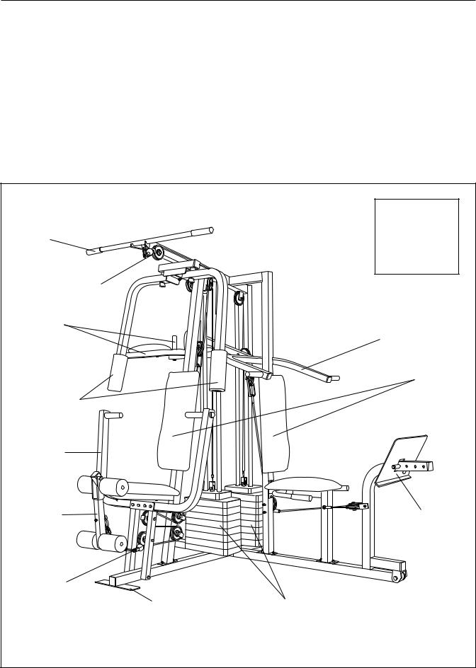
Before reading further, please review the drawing below and familiarize yourself with the parts that are labeled.
|
ASSEMBLED |
||
|
DIMENSIONS: |
||
Lat Bar |
Height: |
76 in. |
|
Width: |
89 in. |
||
|
|||
|
Length: 64 in. |
||
High Pulley Station |
|
|
|
VKR Arms |
|
|
|
|
Military Press Arm |
||
|
|
Backrests |
|
Butterfly Arms |
|
|
|
Press Arm |
|
|
|
Leg Lever |
|
Leg Press |
|
|
|
Plate |
|
Low Pulley |
|
|
|
Station |
Weight Stacks |
|
|
Foot Plate |
|
||
|
4 |
|
|
ASSEMBLY
Before beginning assembly, carefully read the following information and instructions:
•Place all parts of the PRO 9648 in a cleared area and remove the packing materials; do not dispose of the packing materials until assembly is completed.
•The assembly is broken into five stages: 1) frame assembly, 2) press and butterfly arm assembly, 3) cable and pulley assembly, 4) seat and backrest assembly, and 5) VKR assembly. The hardware for each stage is packaged separately.
•Wait until you begin each assembly stage to open the parts bag labeled for that assembly stage.
•For help identifying the small parts used in assembly, use the PART IDENTIFICATION
CHART located in the center of this manual.
Note: Some small parts may have been preattached for shipping. If a part is not in the parts bag, check to see if it has been pre-attached.
•As you assemble the PRO 9648 be sure that all parts are oriented as shown in the drawings.
•Tighten all parts as you assemble them, unless instructed to do otherwise.
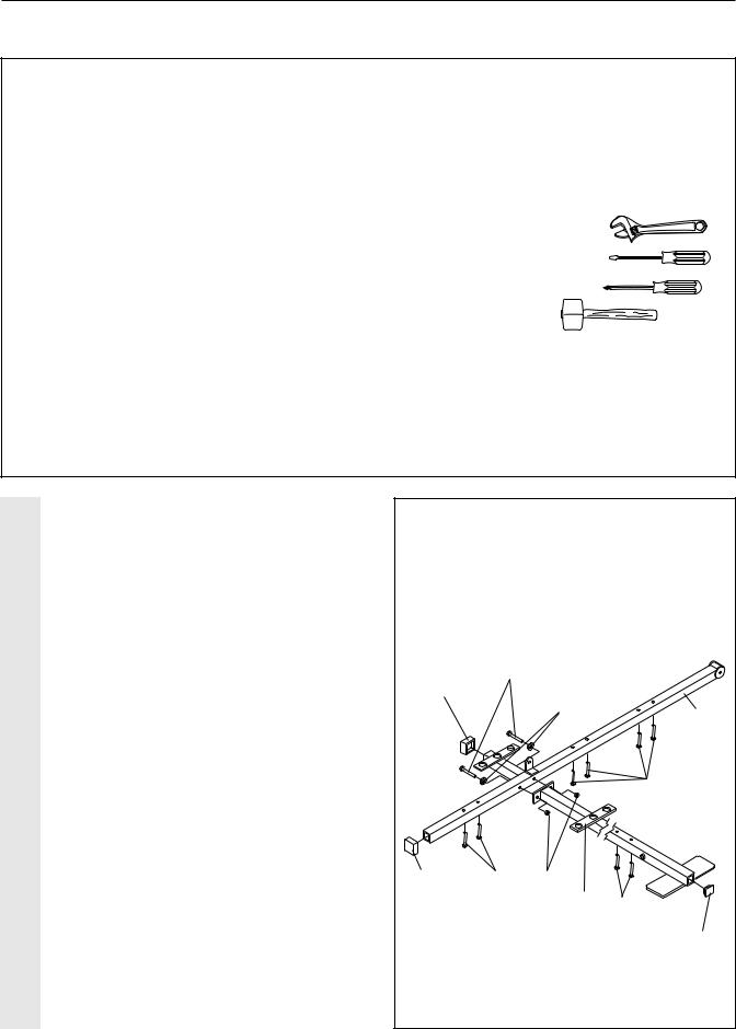
THE FOLLOWING TOOLS (NOT INCLUDED) ARE REQUIRED FOR ASSEMBLY:
• Two (2) adjustable wrenches
• One (1) standard screwdriver
• One (1) phillips screwdriver
• One (1) rubber mallet
•Lubricant, such as grease or petroleum jelly, and soapy water will also be needed.
Assembly will be more convenient if you have the following tools: A socket set, a set of open-end or closed-end wrenches, or a set of ratchet wrenches.
FRAME ASSEMBLY
1. Before beginning assembly, be sure that |
1 |
|
|
|
|
you have read and understand the infor- |
|
|
|
|
|
|
|
|
|
|
|
mation in the box above. |
|
|
|
|
|
Locate and open the parts bag labeled |
|
|
|
|
|
“FRAME ASSEMBLY.” |
|
|
|
|
|
Press two 2” Square Outer Caps (51) onto |
|
|
|
|
|
the indicated locations on the Stabilizer (5). |
|
|
|
|
|
Press a 2” Square Inner Cap (27) into the |
|
11 |
|
|
|
end of the Base (4). |
|
|
|
|
|
51 |
|
|
|
|
|
|
|
|
|
|
|
Insert six 5/16” x 2 1/2” Carriage Bolts (1) up |
|
|
8 |
|
5 |
|
|
|
|
||
through the Stabilizer (5). Insert two 5/16” x |
|
|
|
|
|
2 1/2” Carriage Bolts up through the Base |
|
|
|
|
|
(4). |
|
|
|
|
1 |
|
|
|
|
|
|
Attach the Base (4) to the Stabilizer (5) with |
|
|
|
|
|
two 5/16” x 2 3/4” Bolts (11), two 5/16” Flat |
|
|
|
|
|
Washers (8), and two 5/16” Nylon Locknuts |
|
|
|
|
|
(3). Do not tighten the Nylon Locknuts |
|
|
|
|
|
yet. |
51 |
1 |
3 |
|
|
|
|
|
|||
|
|
|
|
4 |
1 |
|
|
|
|
|
|
|
|
|
|
|
27 |
5
FRAME ASSEMBLY
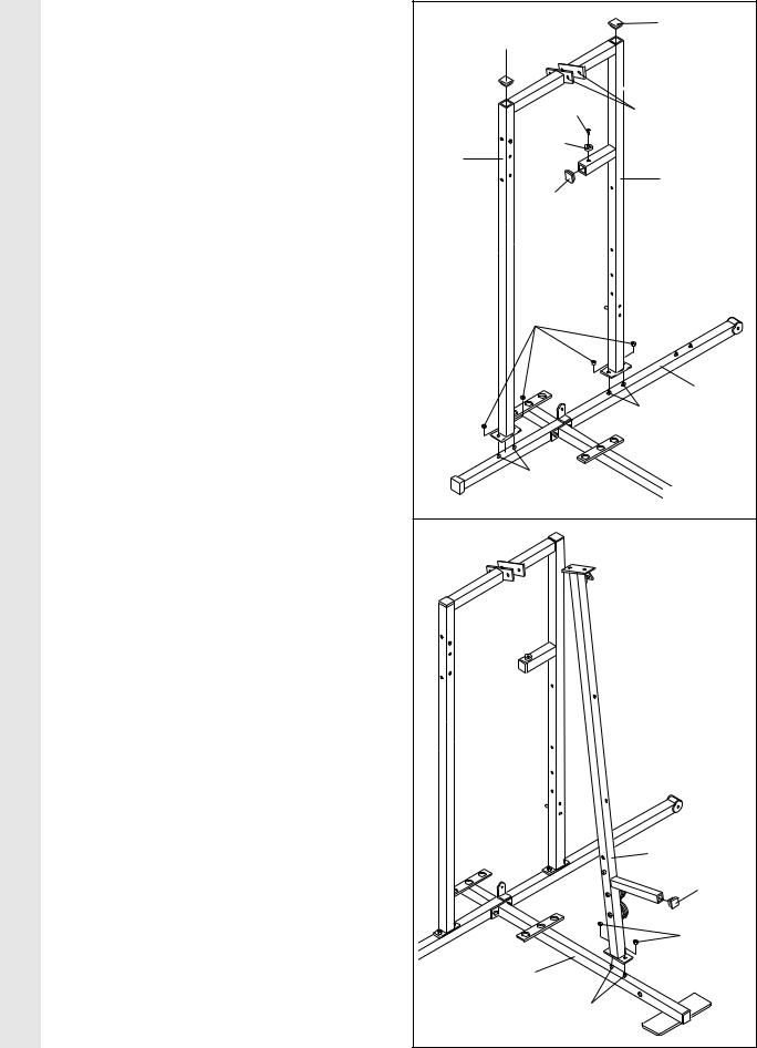
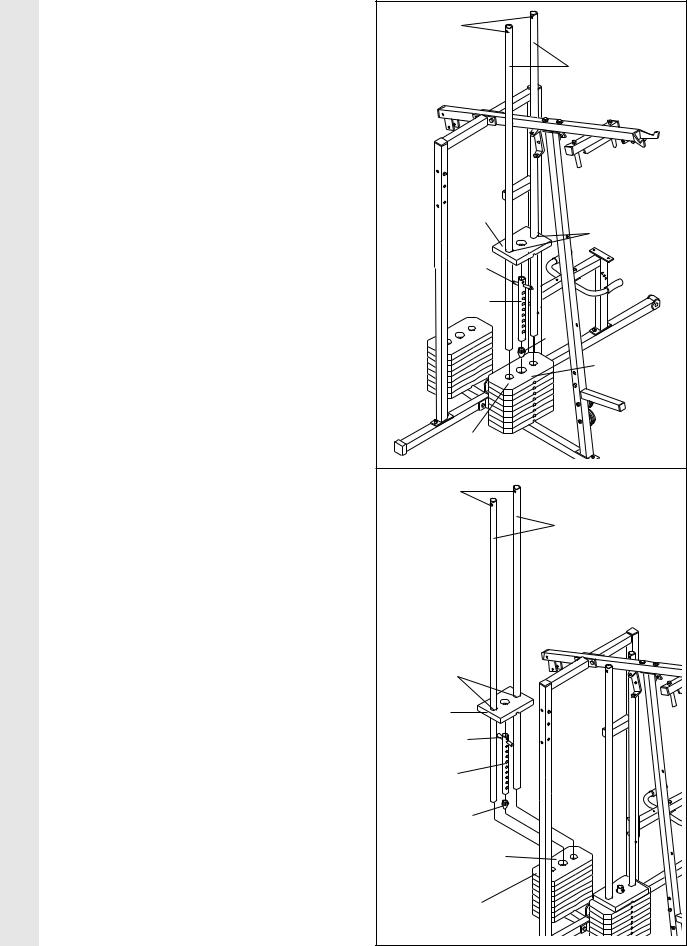
2. Slide the VKR Upright (74) and the Leg Press |
2 |
|
27 |
Upright (56) onto the indicated 5/16” x 2 1/2” |
|
||
|
27 |
||
Carriage Bolts (1) in the Stabilizer (5). The |
|
|
|
|
|
|
|
high side of the brackets on the VKR |
|
|
|
Upright and Leg Press Upright should be |
|
|
|
on the side shown. Hand-tighten four 5/16” |
|
87 |
|
Nylon Locknuts (3) onto the Carriage Bolts. |
|
High Sides |
|
|
|
||
Do not tighten the Nylon Locknuts yet. |
|
91 |
of Brackets |
|
|
|
|
Press two 2” Square Inner Caps (27) into the |
|
74 |
|
|
|
56 |
|
Leg Press Upright (56). Press a 2” Square |
|
|
|
|
27 |
|
|
Inner Cap into the VKR Upright (74). |
|
|
|
Attach the Rubber Bumper (91) to the Leg |
|
|
|
Press Upright (56) with the #8 x 1/2” Self-tap- |
|
|
|
ping Screw (87). |
|
|
|
|
|
3 |
|
|
|
|
5 |
|
|
|
1 |
|
|
1 |
|
3. Slide the Front Upright (42) onto the 5/16” x |
3 |
|
|
2 1/2” Carriage Bolts (1) in the Base (4). |
|
|
|
|
|
|
|
Hand-tighten a 5/16” Nylon Locknut (3) onto |
|
|
|
each Carriage Bolt. Do not tighten the |
|
|
|
Nylon Locknuts yet. |
|
|
|
Press a 1” Square Inner Cap (6) into the |
|
|
|
Front Upright (42). |
|
|
|
|
|
|
42 |
|
|
|
6 |
|
|
|
3 |
|
|
4 |
|
|
|
|
1 |
6
FRAME ASSEMBLY
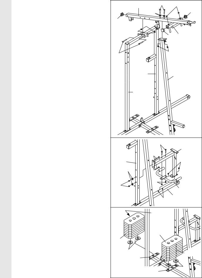
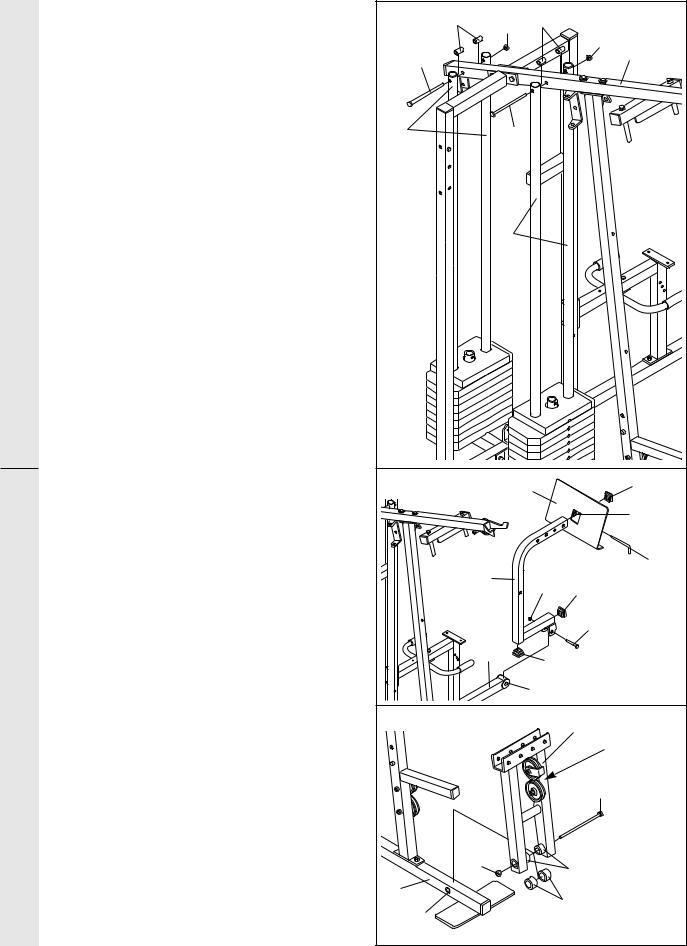
4.Press a 2” Square Inner Cap (27) into the end of the Top Frame (55). Press a 1 3/4” Square Inner Cap (44) into each end of the crossbar on the Top Frame. Press two 1” Round Inner Caps (49) into the top of the crossbar.
Attach the Top Frame (55) to the VKR Upright (74) and the Leg Press Upright (56) with two 5/16” x 2 3/4” Bolts (11) and two 5/16” Nylon Locknuts (3).
Attach the Top Frame (55) to the Front Upright (42) with two 5/16” x 2 3/4” Bolts (11), two 5/16” Flat Washers (8), and two 5/16” Nylon Locknuts (3).
5.Slide the Rear Seat Frame (100) onto the indicated 5/16” x 2 1/2” Carriage Bolts (1) in the Stabilizer (5). Hand-tighten two 5/16” Nylon Locknuts (3) onto the Carriage Bolts.
Attach the other end of the Rear Seat Frame (100) to the Leg Press Upright (56) with two 5/16” x 2 3/4” Bolts (11), two 5/16” Flat Washers (8), and two 5/16” Nylon Locknuts (3).
Attach the Handle (82) to the Rear Seat Frame (100) with two 5/16” x 2 1/2” Carriage Bolts (1) and two 5/16” Nylon Locknuts (3).
Tighten all Nylon Locknuts used in steps 1–5.
6.Set two Weight Bumpers (19) on the bracket on the Base (4) as shown. Set two Weight Bumpers (19) on the bracket on the Stabilizer
(5).
Stack eight Weights (25) onto each set of Weight Bumpers (19). Be sure that the pin grooves are all on the same side of each stack of Weights.
Be careful not to tip either stack of Weights (25) until step 8 is complete.
7
4 |
55 |
11 |
49 |
|
|
|
|
|
|
8 |
44 |
|
|
|
|
27 |
3 |
|
|
|
|
|
|
|
|
44 |
Crossbar |
11 |
|
3 |
|
|
|
|
|
|
56 |
|
42 |
|
74 |
|
|
5 |
|
1 |
|
|
|
|
|
|
|
11 |
|
|
56 |
|
3 |
|
|
|
|
|
8 |
|
|
3 |
|
3 |
|
|
|
82 |
|
|
|
|
|
|
|
5 |
|
|
|
1 |
|
6 |
|
Pin |
|
|
|
Grooves |
|
|
|
25 |
|
25 |
|
|
|
|
19 |
|
Pin |
|
5—Bracket |
|
Grooves |
|
|
|
|
|
4—Bracket |
19 |
|
|
|
||
FRAME ASSEMBLY
7. Press a Weight Tube Bumper (64) into the |
7 |
|
|
end of a Weight Tube (63). Insert the Weight |
Holes |
||
|
|||
Tube into the front stack of Weights (25). Be |
|
|
|
sure that the pin on the Weight Tube is sit- |
|
62 |
|
ting in the pin grooves in the top Weight. |
|
||
Lubricate the inside of the holes in a Top |
|
|
|
Weight (65). Set the Top Weight onto the front |
|
|
|
stack of Weights (25). Insert both Long |
|
|
|
Weight Guides (62) into the stack of Weights. |
|
|
|
Be sure that the holes in the Weight |
|
|
|
Guides are at the top, as shown. |
|
|
|
|
|
65 |
|
|
|
Lubricate |
|
|
|
Pin |
|
|
|
63 |
|
|
|
64 |
|
|
|
Pin Grooves |
|
|
|
25 |
|
8. Press a Weight Tube Bumper (64) into the |
|
|
|
end of the other Weight Tube (63). Insert the |
8 |
Holes |
|
Weight Tube into the rear stack of Weights |
|
||
|
|
||
(25). Be sure that the pin on the Weight |
|
|
|
Tube is sitting in the pin grooves in the top |
|
73 |
|
Weight. |
|
|
|
Lubricate the inside of the holes in the other |
|
|
|
Top Weight (65). Set the Top Weight onto the |
|
|
|
rear stack of Weights (25). Insert both Short |
|
|
|
Weight Guides (73) into the stack of Weights. |
|
|
|
Be sure that the holes in the Weight |
|
|
|
Guides are at the top, as shown. |
|
|
|
|
|
Lubricate |
|
|
|
65 |
|
|
|
Pin |
|
|
|
63 |
|
|
|
64 |
|
|
|
Pin Grooves |
|
|
|
25 |
|
8 |
|
|
FRAME ASSEMBLY
ARM ASSEMBLY
9. |
Attach the upper ends of the Short Weight |
9 |
61 |
|
61 |
|
|
|
Guides (73) to the Top Frame (55) with a 5/16” |
3 |
|
|
|||
|
|
|
|
||||
|
x 6” Bolt (60), two 1/2” x 3/4” Spacers (61), and |
|
|
|
|
|
3 |
|
a 5/16” Nylon Locknut (3). |
60 |
|
|
|
|
55 |
|
|
|
|
|
|
|
|
|
Attach the upper ends of the Long Weight |
|
|
|
|
|
|
|
Guides (62) to the Top Frame (55) with a 5/16” |
|
|
|
|
|
|
|
x 6” Bolt (60), two 1/2” x 3/4” Spacers (61), and |
73 |
|
60 |
|
|
|
|
a 5/16” Nylon Locknut (3). |
|
|
|
|||
|
|
|
|
62 |
|
|
|
10. |
Locate and open the parts bag labeled |
10 |
|
|
95 |
|
27 |
|
“ARM ASSEMBLY.” |
|
|
|
|||
|
|
|
|
|
|||
|
Be sure there is a Bushing (98) in each side of |
|
|
|
|
|
Welded |
|
|
|
|
|
|
Tube |
|
|
the Stabilizer (5). Press a 2” Square Inner Cap |
|
|
|
|
|
|
|
|
|
|
|
|
|
|
|
(27) into each end of the Leg Press Arm (96). |
|
|
|
|
|
97 |
|
|
|
|
96 |
|
|
|
|
Lubricate a 3/8” x 3 1/4” Bolt (67). Attach the |
|
|
21 |
27 |
||
|
|
|
|
||||
|
Leg Press Arm (96) to the Stabilizer (5) with the |
|
|
|
|
|
|
|
Bolt and a 3/8” Nylon Locknut (21). Do not over- |
|
|
|
|
|
67—Lubricate |
|
tighten the Nylon Locknut. The Leg Press |
|
|
|
|
|
|
|
|
|
|
|
|
|
|
|
Arm must be able to pivot freely. |
|
|
5 |
27 |
|
|
|
|
|
|
|
|
||
|
|
|
|
|
|
|
|
|
Align the welded tubes on the Leg Press Plate |
|
|
|
98 |
|
|
|
(95) with one set of holes in the Leg Press Arm |
|
|
|
|
|
|
|
|
|
|
|
|
|
|
|
(96). Attach the Leg Press Plate to the Leg |
11 |
|
|
|
17 |
|
|
Press Arm with the Press Pin (97). |
|
|
|
|
Pulleys |
|
|
|
|
|
|
|
|
must be on |
11. |
Press a 1” x 7/8” Plastic Bushing (90) onto |
|
|
|
|
|
this side |
|
|
|
|
|
|
||
|
each welded spacer on the Press Frame (17). |
|
|
|
|
|
59—Lubricate |
|
Slide the Press Frame into place onto the Base |
|
|
|
|
|
|
|
(4). Note: This will be a tight fit. The Plastic |
|
|
|
|
|
|
|
Bushings should fit on each end of the indi- |
|
|
|
|
|
|
|
cated tube in the Base. Make sure that the |
|
|
|
|
|
|
|
pulleys are on the side shown. |
|
|
21 |
|
Welded Spacers |
|
|
|
|
|
|
|||
|
|
|
|
|
|
||
|
Lubricate the 3/8” x 8” Bolt (59). Attach the |
4 |
|
|
|
90 |
|
|
Press Frame (17) to the Base (4) with the Bolt |
Tube |
|
|
|
|
|
|
and a 3/8” Nylon Locknut (21). |
|
|
|
|
|
|
|
|
|
|
|
|
|
|
9
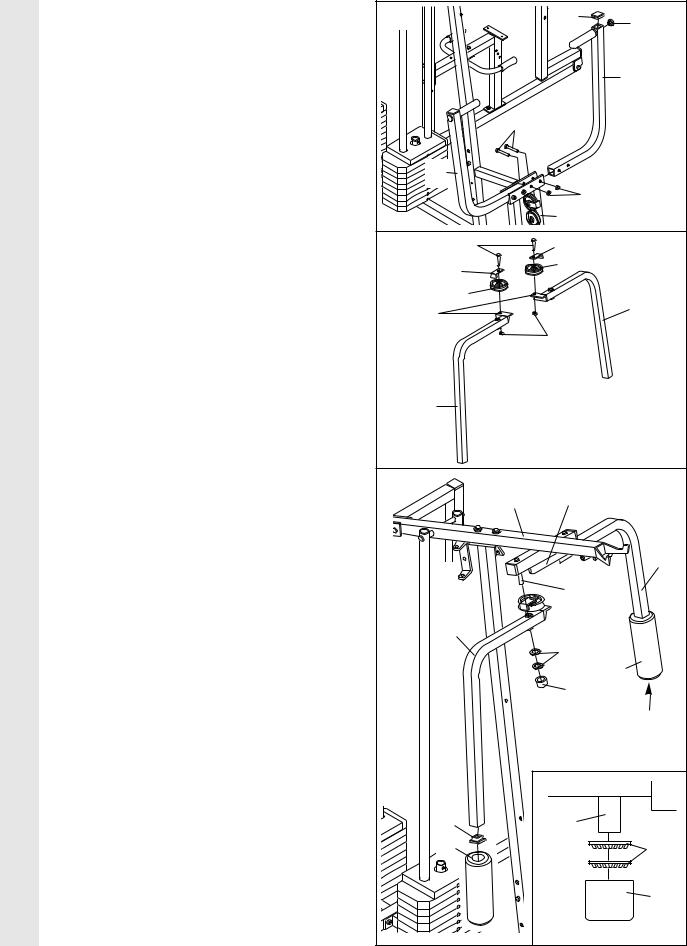
ARM ASSEMBLY
12.Press a 1” Round Inner Cap (49) into one of the Press Arms (46). Press a 1 3/4” Square Inner Cap (44) into the Press Arm.
Attach the Press Arm (46) to one side of the Press Frame (17) with two 5/16” x 2 1/2” Bolts (22) and two 5/16” Nylon Locknuts (3).
Assemble the other Press Arm (46) in the same manner.
13.Identify the Right Arm (48) and the Left Arm (47). Note the position of the welded bracket on each Arm. Arm identification is very important for step 14.
Attach a “V”-Pulley (50) and a Long Cable Trap (31) to the Right Arm (48) with a 3/8” x 2 1/2” Bolt (86) and a 3/8” Nylon Locknut (21).
Do not tighten the Nylon Locknut yet.
Attach a “V”-Pulley (50) and a Long Cable Trap (31) to the Left Arm (47) in the same manner.
14.Lubricate both axles on the Top Frame (55).
Slide the Right Arm (48) onto the right axle.
Note: Be careful not to confuse the Right Arm with the Left Arm (47); refer to step 13 to identify the Right Arm. Be sure that the upper end of the Right Arm is behind the indicated bracket on the Top Frame (55).
Tap two 1” Retainers (69) and a 1” Round Cover Cap (70) onto the axle. Be sure that the teeth on the Retainers bend toward the Round Cover Cap, as shown in the inset drawing.
Attach the Left Arm (47) in the same manner.
Press 1 3/4” Square Inner Caps (44) into the lower ends of the Right and Left Arms (47, 48). Wet the lower end of each Arm with soapy water. Slide a 10” Pad (45) onto the lower end of each Arm.
10
12 |
|
44 |
49 |
|
|
|
|
|
|
|
46 |
|
22 |
|
|
46 |
|
|
|
|
|
3 |
|
|
|
17 |
|
13 |
86 |
31 |
|
|
31 |
50 |
|
|
|
|
|
Welded |
50 |
|
47 |
|
|
||
Brackets |
|
|
|
|
|
21 |
|
48 |
|
|
|
14 |
|
|
|
|
55 |
Bracket |
|
|
|
|
47 |
|
|
Lubricate |
|
|
|
Axle |
|
|
48 |
|
|
|
|
69 |
|
|
|
|
45 |
|
|
70 |
|
|
|
|
44 |
|
|
Axle |
|
|
|
|
69 |
|
|
|
70 |
 Loading...