


Model No. WEANSY1977.0
Serial No.
Write the serial number in the space above for reference.
Seri al
al Number Decal (Under Seat)
QUESTIONS?
If you have questions, or if there are missing or damaged parts, please contact the establishment where you purchased this product.
 CAUTION
Read all precautions and instructions in this manual before using this equipment. Save this manual for future reference.
USER’S MANUAL
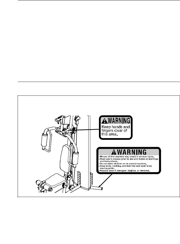
TABLE OF CONTENTS
WARNING DECAL PLACEMENT . . . . . . . . . . . . . . . . . . . . . . . . . . . . . . . . . . . . . . . . . . . . . . . . . . . . . . . . . . . . . 2 IMPORTANT PRECAUTIONS . . . . . . . . . . . . . . . . . . . . . . . . . . . . . . . . . . . . . . . . . . . . . . . . . . . . . . . . . . . . . . . . 3 BEFORE YOU BEGIN . . . . . . . . . . . . . . . . . . . . . . . . . . . . . . . . . . . . . . . . . . . . . . . . . . . . . . . . . . . . . . . . . . . . . . 4 PART IDENTIFICATION CHART . . . . . . . . . . . . . . . . . . . . . . . . . . . . . . . . . . . . . . . . . . . . . . . . . . . . . . . . . . . . . .5 ASSEMBLY . . . . . . . . . . . . . . . . . . . . . . . . . . . . . . . . . . . . . . . . . . . . . . . . . . . . . . . . . . . . . . . . . . . . . . . . . . . . . . 6 ADJUSTMENT . . . . . . . . . . . . . . . . . . . . . . . . . . . . . . . . . . . . . . . . . . . . . . . . . . . . . . . . . . . . . . . . . . . . . . . . . . . 18 WEIGHT RESISTANCE CHART . . . . . . . . . . . . . . . . . . . . . . . . . . . . . . . . . . . . . . . . . . . . . . . . . . . . . . . . . . . . . .20 CABLE DIAGRAM . . . . . . . . . . . . . . . . . . . . . . . . . . . . . . . . . . . . . . . . . . . . . . . . . . . . . . . . . . . . . . . . . . . . . . . . .21 MAINTENANCE . . . . . . . . . . . . . . . . . . . . . . . . . . . . . . . . . . . . . . . . . . . . . . . . . . . . . . . . . . . . . . . . . . . . . . . . . .22 EXERCISE GUIDELINES . . . . . . . . . . . . . . . . . . . . . . . . . . . . . . . . . . . . . . . . . . . . . . . . . . . . . . . . . . . . . . . . . . 23 PART LIST . . . . . . . . . . . . . . . . . . . . . . . . . . . . . . . . . . . . . . . . . . . . . . . . . . . . . . . . . . . . . . . . . . . . . . . . . . . . . .25 EXPLODED DRAWING . . . . . . . . . . . . . . . . . . . . . . . . . . . . . . . . . . . . . . . . . . . . . . . . . . . . . . . . . . . . . . . . . . . .26 ORDERING REPLACEMENT PARTS . . . . . . . . . . . . . . . . . . . . . . . . . . . . . . . . . . . . . . . . . . . . . . . . . .Back Cover LIMITED WARRANTY . . . . . . . . . . . . . . . . . . . . . . . . . . . . . . . . . . . . . . . . . . . . . . . . . . . . . . . . . . . . . . Back Cover
WARNING DECAL PLACEMENT
The decals shown here have been applied in the locations shown. If a decal is missing or illegible, see the front cover of this manual and request a free replacement decal. Apply the decal in the location shown. Note: The decals may not be shown at actual size.
Note: This decal is on both sides of the upright.
WEIDER is a registered trademark of ICON IP, Inc.
2

IMPORTANT PRECAUTIONS
 WARNING: To reduce the risk of serious injury, read all important precautions and instructions in this manual and all warnings on your weight system before using your weight system. ICON assumes no responsibility for personal injury or property damage sustained by or through the use of this product.
1.Before beginning any exercise program, con- 9. Keep hands and feet away from moving parts. sult your physician. This is especially impor-
tant for persons over the age of 35 or persons with pre-existing health problems.
2.Use the weight system only as described in this manual.
3.It is the responsibility of the owner to ensure that all users of the weight system are adequately informed of all precautions.
4.The weight system is intended for home use only. Do not use the weight system in any commercial, rental, or institutional setting.
5.Keep the weight system indoors, away from moisture and dust. Place the weight system on a level surface, with a mat beneath it to protect the floor or carpet. Make sure that there is enough clearance around the weight system to mount, dismount, and use it.
6.Make sure that all parts are properly tightened each time the weight system is used. Replace any worn parts immediately.
7.Keep children under age 12 and pets away from the weight system at all times.
8.Always wear athletic shoes for foot protection while exercising.
10.The weight system is designed to support a maximum user weight of 300 lbs. (136 kg).
11.Always secure the weight stack with the lock pin and lock after exercising to prevent unauthorized use of the weight system (see LOCKING THE WEIGHT STACK on page 19).
12.Make sure that the cables remain on the pulleys at all times. If the cables bind while you are exercising, stop immediately and make sure that the cables are on the pulleys. Replace all cables at least every two years.
13.Always stand on the foot plate when performing an exercise that could cause the weight system to tip.
14.Never release the arms, leg lever, lat bar, or handle strap while weights are raised. The weights will fall with great force.
15.Always disconnect the lat bar from the weight system when performing an exercise that does not require the lat bar.
16.If you feel pain or dizziness while exercising, stop immediately and cool down.
3
BEFORE YOU BEGIN
Thank you for selecting the versatile WEIDER® C625 weight system. The weight system offers a selection of weight stations designed to develop every major muscle group of the body. Whether your goal is to tone your body, build dramatic muscle size and strength, or improve your cardiovascular system, the weight system will help you to achieve the specific results you want.
For your benefit, read this manual carefully before using the weight system. If you have questions after
reading this manual, see the front cover of this manual. To help us assist you, please note the product model number and serial number before contacting us. The model number and the location of the serial number decal are shown on the front cover of this manual.
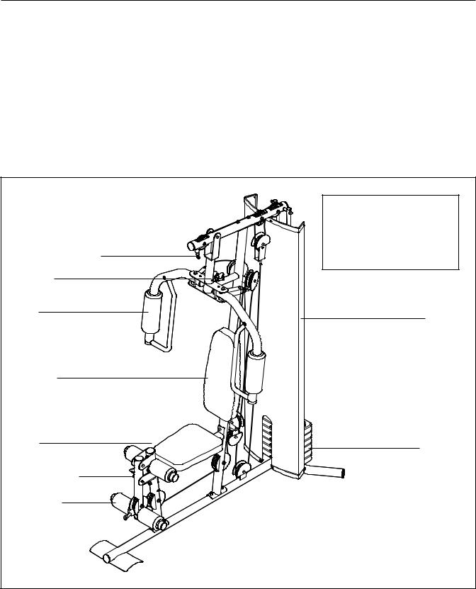
Before reading further, review the drawing below and familiarize yourself with the parts that are labeled.
High Pulley Station
Arm Pin
Arm
Backrest
Right Side
Seat
Leg Lever Pin
Leg Lever
Low Pulley Station 
Assembled Dimensions: |
|
Height: |
76 in. (193 cm) |
Width: |
38 in. (97 cm) |
Depth: |
65 in. (165 cm) |
Weight: 200 lbs. (91 kg) |
|
|
Shroud |
Left Side |
|
|
Weights |
Foot Plate 
Note: The terms “right side” and “left side” are determined relative to a person sitting on the seat; they do not correspond to right and left on the drawings in the manual.
4
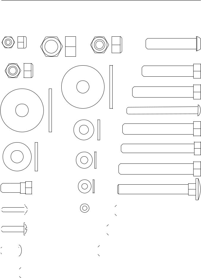
PART IDENTIFICATION CHART
See the drawings below to identify small parts used in assembly. The number in parentheses by each drawing is the key number of the part, from the PART LIST near the end of this manual. Note: Some small parts may have been preattached. If a part is not in the parts bag, check to see if it has been preattached.
M6 Locknut (87) |
M10 x 45mm Button Bolt (77) |
M10 Nylon Locknut (56) |
|
M12 Nut (84) |
|
|
M10 x 46mm Bolt (81) |
M8 Nylon Locknut (58) |
|
|
M10 x 51mm Bolt (66) |
M10 Large Washer (80) |
M6 x 63mm Screw (70) |
|
|
|
M10 x 63mm Bolt (75) |
Large Washer (85) |
|
M8 Washer (59) |
M8 x 65mm Bolt (68) |
|
|
M6 Washer (82) |
M10 x 67mm Bolt (71) |
|
|
M10 Washer (57) |
|
M8 x 63mm Carriage Bolt (78)
M5 Washer (72)
M8 x 22mm Shoulder Bolt (65)
|
|
|
|
|
|
|
|
|
|
|
|
|
|
|
|
|
|
|
|
|
|
|
|
|
|
|
|
|
|
|
|
M10 x 70mm Bolt (86) |
|
|
|
|
|
|
|
|
|
|
|
|
|
|
|
|
|
|
|
|
|
|
|
|
|
|
|
|
|
|
|
|
|
|
|
M4 x 20mm Self-tapping Screw (69) |
M4 Washer (33) |
|
|
|||||||||||||
|
|
|||||||||||||||
|
|
|||||||||||||||
|
|
|
|
|
|
|
|
|
|
|
|
|
|
|
|
|
|
|
|
|
|
|
|
|
|
|
|
|
|
|
|
|
|
|
|
|
|
|
|
|
|
|
|
|
|
|
|
|
M10 x 77mm Bolt (79) |
|
|
|
|
|
|
|
|
|
|
|
|
|
|
|
|
|
|
|
|
|
|
|
|
|
|
|
|
|
|
|
|
|
|
|
|
|
|
|
|
|
|
|
|
|
|
|
|
|
|
|
|
|
|
|
|
|
|
|
|
|
|
|
|
|
||||
|
|
|
|
|
|
|
|
|
|
|
|
|
|
|
|
|
|
M5 x 20mm Self-tapping Screw (64) |
|
|
|
|
|
|
|
|
|
|
|||||
|
|
|
|
|
|
|
|
|
|
|
||||||
|
|
|
|
|
|
|
|
|
|
|
|
|
|
|
|
|
|
|
|
|
|
|
|
|
|
|
|
|
|
|
|
|
|
|
|
|
|
|
|
|
|
|
|
|
|
|
|
|
M10 x 85mm Bolt (67) |
|
|
|
|
|
|
|
|
|
|
|
|
|
|
|
|
|
|
|
|
|
|
|
|
|
|
|
|
|
|
|
|
|
|
|
|
|
|
|
|
|
|
|
|
|
|
|
|
|
|
|
|
|
|
|
|
|
|
|
|
|
|
|
|
|
|
|
|
|
M6 x 16mm Screw (62) |
|
|
|
|
|
|
|
|
|
|
||||||
|
|
|
|
|
|
|
|
|
|
|||||||
|
|
|
|
|
|
|
|
|
|
|
|
|
|
|
|
|
|
|
|
|
|
|
|
|
|
|
|
|
|
|
|
|
|
|
|
|
|
|
|
|
|
|
|
|
|
|
|
|
M10 x 155mm Bolt (74) |
|
|
|
|
|
|
|
|
|
|
|
|
|
|
|
|
|
|
|
|
|
|
|
|
|
|
|
|
|
|
|
|
|
|
|
|
|
|
|
|
|
|
|
|
|
|
|
|
|
|
|
|
|
|
|
|
|
|
|
|
|
|
|
|
|
|
|
|
|
|
|
|
|
|
|
|
|
|
|
|
|
|
|
|
|
|
5
ASSEMBLY
Make Assembly Easier
Everything in this manual is designed to ensure that the weight system can be assembled successfully by almost anyone. By setting aside plenty of time, assembly will go smoothly.
Before beginning assembly, carefully read the following information and instructions:
•Assembly requires two persons.
•Because of its size, the weight system should be assembled in the location where it will be used. Make sure that there is enough clearance to walk around the weight system while you assemble it.
•To make assembly as easy as possible, we have divided the assembly process into four stages. The parts needed for each stage are found in individual bags. Important: Wait until you begin each stage to open the parts bag for that stage. Place all parts in a cleared area and remove the packing materials. Do not dispose of
the packing materials until assembly is completed.
•Tighten all parts as you assemble them, unless instructed to do otherwise.
•As you assemble the weight system, make sure all parts are oriented as shown in the drawings.
•For help identifying small parts, use the PART IDENTIFICATION CHART on page 5.
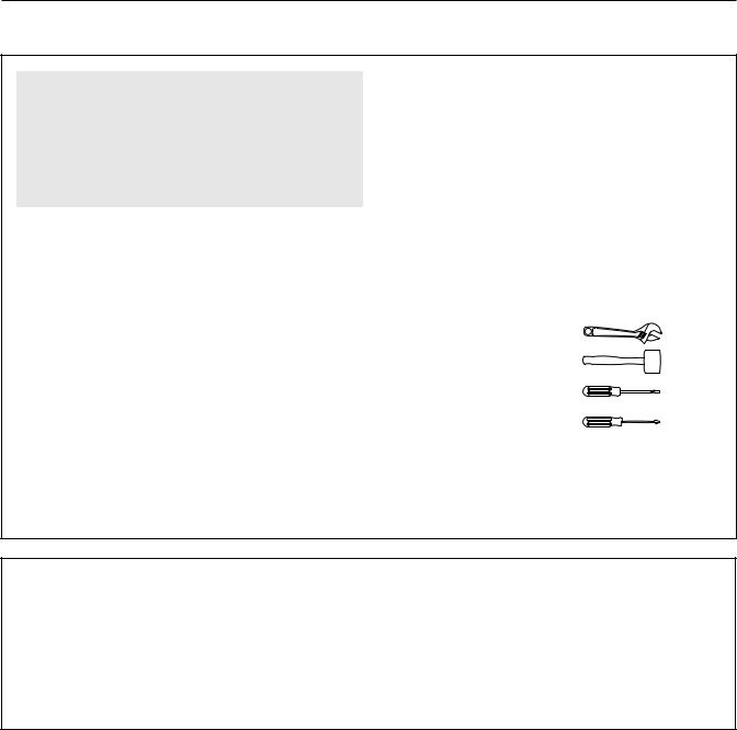
•Assembly requires the included hex key(s)
 and the following tools (not included):
two adjustable wrenches
one rubber mallet
one standard screwdriver
one Phillips screwdriver
Assembly may be more convenient if you have a socket set, a set of open-end or closed-end wrenches, or a set of ratchet wrenches.
The Four Stages of the Assembly Process
Frame Assembly—You will begin by assembling |
Cable Assembly—During this stage you will attach |
the base and the uprights that form the skeleton of |
the cables and pulleys that connect the arms to the |
the weight system. |
weights. |
Arm Assembly—During this stage you will assem- |
Seat Assembly—During the final stage you will |
ble the arms and other moving parts. |
assemble the seat, the backrest, and other parts. |
|
|
6
Frame Assembly
1.
Before beginning assembly, make sure that you understand the information in the box on page 6. See the PART IDENTIFICATION CHART on page 5 for help identifying small parts.
Insert four M8 x 63mm Carriage Bolts (78) up through the Base (1). Note: It may be helpful to place a piece of tape over the bolt heads to hold them in place.
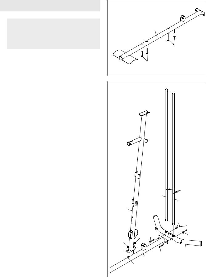
2.Attach the Base (1) and the two Weight Guides (21) to the Stabilizer (2) with two M10 x 67mm Bolts (71), two M10 Washers (57), and two M10 Nylon Locknuts (56). Make sure that the indicated holes in the Weight Guides are nearer the bottom. Fully tighten the Nylon Locknuts.
Attach the Upright (3) to the Base (1) with the indicated two M8 x 63mm Carriage Bolts (78) and two M8 Nylon Locknuts (58). Do not tighten the
Nylon Locknuts yet.
1 |
|
|
|
1 |
|
|
78 |
|
|
78 |
|
2 |
|
|
|
Holes |
|
|
21 |
|
|
21 |
|
3 |
|
|
|
57 |
56 |
58 |
71 |
57 |
58 |
|
|
|
71 |
2 |
1 |
|
|
|
|
|
78 |
|
|
7

3.Attach the Front Leg (7) to the Base (1) with the two indicated M8 x 63mm Carriage Bolts (78) and two M8 Nylon Locknuts (58). Do not tighten the
Nylon Locknuts yet.
Attach the Leg Bumper (60) to the Front Leg (7) with an M4 x 20mm Self-tapping Screw (69) and an M4 Washer (33). Make sure that the end of the Bumper is angled upward.
4.Attach the Seat Frame (6) to the Upright (3) with two M8 x 65mm Bolts (68), two M8 Washers (59), and two M8 Nylon Locknuts (58). Do not tighten the Nylon Locknuts yet.
Attach the Seat Frame (6) to the Front Leg (7) in the same way.
5.Slide the two Weight Bumpers (27) onto the Weight Guides (21). Orient the six Weights (22) so that the pin holes are on the bottom as shown. Slide the Weights onto the Weight Guides.
Insert the Weight Tube Cap (23) into the Weight Tube (24). Insert the Weight Tube into the six Weights (22). Make sure that the pin on the
Weight Tube is oriented as shown.
Grease the indicated holes in the Top Weight (25) with the included grease packet. Slide the Top Weight onto the Weight Guides (21).
3 |
|
|
|
|
|
|
|
7 |
|
|
Up |
|
|
|
|
33 |
|
|
|
|
69 |
60 |
58 |
|
|
58 |
|
|
|
|
|
|
|
|
|
|
|
1 |
|
|
|
|
78 |
|
4 |
|
68 |
|
|
|
|
|
|
|
|
68 |
|
59 |
|
|
|
|
58 |
|
|
6 |
|
|
|
|
|
68 |
58 |
|
|
68 |
59 |
|
|
|
59 |
|
|
|
|
|
7 |
3 |
|
|
|
|
|
|
|
58 |
|
|
|
|
59 |
|
|
|
5 |
|
|
21 |
|
|
21 |
|
|
|
|
|
|
|
|
|
|
|
Grease |
|
|
25 |
|
|
|
|
|
|
Pin |
|
|
|
|
24 |
|
|
Pin |
|
|
|
|
Hole |
|
23 |
|
|
|
|
|
|
|
|
|
22 |
|
|
|
|
27 |
|
8
6. Attach the Top Frame (4) to the Upright (3) with |
6 |
|
|
|
two M8 x 65mm Bolts (68), two M8 Washers (59), |
|
|
|
|
|
68 56 |
57 |
76 |
|
and two M8 Nylon Locknuts (58). Do not tighten |
|
|||
|
|
|||
the Nylon Locknuts yet. |
|
|
|
|
Attach the Top Frame (4) between the Weight |
59 |
|
|
57 |
|
|
74 |
||
|
|
|
||
Guides (21) with an M10 x 155mm Bolt (74), two |
4 |
|
|
|
M10 Washers (57), two 19mm Spacers (76), and |
|
|
|
|
|
|
|
|
|
an M10 Nylon Locknut (56). Do not tighten the |
58 |
58 |
|
|
Nylon Locknuts yet. |
|
|
||
|
|
|
|
|
3 |
|
|
|
21 |
21 |
|
|
|
|
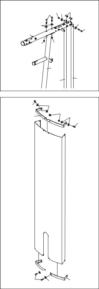
7. Attach the Left Cap (19) and the Right Cap (20) |
7 |
|
|
to the bottom of the Shroud (17) with two M5 x |
82 |
|
|
62 |
|
||
20mm Self-tapping Screws (64) and two M5 |
|
|
|
|
|
87 |
|
Washers (72). |
|
|
|
18 |
|
82 |
|
|
|
||
Attach the Top Cap (18) to the top of the Shroud |
|
|
62 |
|
|
|
|
(17) with two M6 x 16mm Screws (62), four M6 |
|
|
|
Washers (82), and two M6 Nylon Locknuts (87). |
|
|
|
17
20 
72

64 |
72 |
19 |
|
|
9
 Loading...