


Model No. WEEVBE2926.0
Serial No.
Write the serial number in the space above for future reference.
 Se
Se rial Number Decal (Under Seat)
QUESTIONS?
As a manufacturer, we are committed to providing complete customer satisfaction. If you have questions, or if there are missing or damaged parts, please call:
08457 089 009
Or write:
ICON Health & Fitness, Ltd.
Unit 4
Revie Road Industrial Estate
Revie Road
Beeston
Leeds, LS118JG
UK
email: csuk@iconeurope.com
 CAUTION
Read all precautions and instructions in this manual before using this equipment. Save this manual for future reference.
USER’S MANUAL

TABLE OF CONTENTS
IMPORTANT PRECAUTIONS . . . . . . . . . . . . . . . . . . . . . . . . . . . . . . . . . . . . . . . . . . . . . . . . . . . . . . . . . . . . . . . . 3 BEFORE YOU BEGIN . . . . . . . . . . . . . . . . . . . . . . . . . . . . . . . . . . . . . . . . . . . . . . . . . . . . . . . . . . . . . . . . . . . . . . 4 PART IDENTIFICATION CHART . . . . . . . . . . . . . . . . . . . . . . . . . . . . . . . . . . . . . . . . . . . . . . . . . . . . . . . . . . . . . .5 ASSEMBLY . . . . . . . . . . . . . . . . . . . . . . . . . . . . . . . . . . . . . . . . . . . . . . . . . . . . . . . . . . . . . . . . . . . . . . . . . . . . . . 6 ADJUSTMENTS . . . . . . . . . . . . . . . . . . . . . . . . . . . . . . . . . . . . . . . . . . . . . . . . . . . . . . . . . . . . . . . . . . . . . . . . . . 12 EXERCISE GUIDELINES . . . . . . . . . . . . . . . . . . . . . . . . . . . . . . . . . . . . . . . . . . . . . . . . . . . . . . . . . . . . . . . . . . .15 PART LIST . . . . . . . . . . . . . . . . . . . . . . . . . . . . . . . . . . . . . . . . . . . . . . . . . . . . . . . . . . . . . . . . . . . . . . . . . . . . . .17 EXPLODED DRAWING . . . . . . . . . . . . . . . . . . . . . . . . . . . . . . . . . . . . . . . . . . . . . . . . . . . . . . . . . . . . . . . . . . . .18 ORDERING REPLACEMENT PARTS . . . . . . . . . . . . . . . . . . . . . . . . . . . . . . . . . . . . . . . . . . . . . . . . . .Back Cover
WEIDER is a registered trademark of ICON IP, Inc.
2

IMPORTANT PRECAUTIONS
 WARNING: To reduce the risk of serious injury, read the following important precautions before using the weight bench.
1.Read all instructions in this manual and all warnings on the weight bench before using the weight bench. Use the weight bench only as described in this manual.
2.It is the responsibility of the owner to ensure that all users of the weight bench are adequately informed of all precautions.
3.The weight bench is intended for home use only. Do not use the weight bench in any commercial, rental, or institutional setting.
4.Keep the weight bench indoors, away from moisture and dust. Place the weight bench on a level surface, with a mat beneath it to protect the floor or carpet.
5.Make sure that there is enough clearance around the weight bench to mount, dismount, and use the weight bench.
6.Inspect and properly tighten all parts regularly. Replace any worn parts immediately.
7.Make sure the set screws attaching the Olympic adapters are properly tightened each time the adapters are used.
8.Keep hands and feet away from moving parts.
9.Always set both weight rests at the same height.
10.Keep children under 12 and pets away from the weight bench at all times.
11.Always wear athletic shoes for foot protection while exercising.
12.The weight bench is designed to support a maximum user weight of 300 lbs. (136 kg) and a maximum total weight of 610 lbs. (277 kg). Do not place more than 310 lbs. (140 kg), including the barbell, on the weight rests. Do not place more than 150 lbs. (68 kg) on the leg lever and the Lat Tower. Note: The weight bench is designed to be used with an Olympic barbell. The weight bench does not include a barbell or weights.
13.Always place an equal amount of weight on each side of the barbell.
14.Always exercise with a partner. Your partner should be ready to catch the barbell if you cannot complete a repetition.
15.If you feel pain or dizziness while exercising, stop immediately and begin cooling down.
16.The decal shown on page 4 has been placed on the weight bench. If the decal is missing or illegible, please call the telephone number on the front cover of this manual and order a free replacement decal. Apply the decal in the location shown.
 WARNING: Before beginning this or any exercise program, consult your physician. This is especially important for persons over the age of 35 or persons with pre-existing health problems. Read all instructions before using. ICON assumes no responsibility for personal injury or property damage sustained by or through the use of this product.
3

BEFORE YOU BEGIN
Thank you for selecting the versatile WEIDER® PRO 550 weight bench. The weight bench offers a selection of weight stations designed to develop every major muscle group of the body. Whether your goal is to tone your body, build dramatic muscle size and strength, or improve your cardiovascular system, the weight bench will help you to achieve the specific results you want.
For your benefit, read this manual carefully before using the weight bench. If you have questions after
reading this manual, see the front cover of this manual. To help us assist you, please note the product model number and serial number before contacting us. The model number is WEEVBE2926.0. The serial number can be found on a decal attached to the weight bench (see the front cover of this manual).
Before reading further, please review the drawing below and familiarize yourself with the parts that are labeled.
Upright |
ASSEMBLED DIMENSIONS: |
|
|
Height: |
152 cm (60 in.) |
|
Width: |
122 cm (48 in.) |
Lat Bar |
Depth: |
183 cm (72 in.) |
|
|
|
Lat Tower |
|
Curl Pad |
|
|
|
|
|
Weight Rest |
Seat |
|
Backrest |
Weight Carriage |
|
Weight |
|
|
Storage Tube |
Leg Lever |
|
Adjustment Tube |
|
|
|
4

PART IDENTIFICATION CHART
See the drawings below to identify small parts used in assembly. The number in parentheses by each drawing is the key number of the part, from the PART LIST on page 17. Note: Some small parts may have been preassembled. If a part is not in the parts bag, check to see if it has been preassembled.
|
M8 x 10mm |
M10 x 93mm Bolt (66) |
|
|
Set Screw (60) |
|
|
M10 Washer (43) |
M4 x 16mm |
|
|
|
Self-tapping |
M10 x 70mm Bolt (55) |
|
|
Screw (57) |
|
|
|
M6 x 16mm |
M10 x 57mm Bolt Set (64) |
|
M8 Washer (50) |
Screw (41) |
||
|
|||
|
|
||
|
M10 x 20mm |
M10 x 60mm Bolt (68) |
|
|
|
||
M6 Washer (54) |
Bolt (65) |
|
|
|
|
||
|
|
M8 x 58mm Bolt (46) |
|
M10 Nylon |
|
|
|
Locknut (58) |
|
M8 x 52mm Bolt (59) |
25mm Round Outer Cap (62)
M8 Nylon |
M10 x 50mm Carriage Bolt (67) |
|||
Locknut (49) |
||||
|
|
|
||
|
|
|
|
|
|
|
|
|
|
|
|
|
|
|
|
|
|
|
|
|
|
|
|
|
|
|
|
|
|
M6 x 40mm Screw (48)
M10 x 145mm Bolt (53)
5
ASSEMBLY
Make Assembly Easier
Everything in this manual is designed to ensure that the weight bench can be assembled successfully by almost anyone. However, the weight bench has many parts and the assembly process will take time. By setting aside plenty of time, assembly will go smoothly.
Before beginning assembly, carefully read the following information and instructions:
•Because of its weight and size, the weight bench should be assembled in the location where it will be used. Make sure that there is enough clearance to walk around the weight bench as you assemble it.
•Place all parts in a cleared area and remove the packing materials. Do not dispose of the packing materials until assembly is completed.
•Tighten all parts as you assemble them, unless instructed to do otherwise.
•As you assemble the weight bench, make sure all parts are oriented as shown in the drawings.
•Assembly requires two persons.
•For help identifying small parts, use the PART IDENTIFICATION CHART.
In addition to the included hex keys and grease packet, the following tools (not included) are required for assembly:
• two adjustable wrenches
• one rubber mallet
• one standard screwdriver
• one Phillips screwdriver
Assembly will be more convenient if you have a socket set, a set of open-end or closed-end wrenches, or a set of ratchet wrenches.
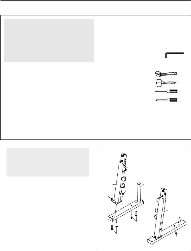
1. |
1 |
|
|
Before beginning assembly, make sure |
|
||
you understand the information in the |
|
|
|
box above. For help identifying small |
|
|
|
parts, use the PART IDENTIFICATION |
|
|
|
CHART on page 5. |
|
|
|
Insert four M10 x 50mm Carriage Bolts (67) up |
4 |
2 |
|
|
|||
through the Right Stabilizer (2). Attach the Right |
|
58 |
|
Upright Base (4) to the Right Stabilizer with the |
58 |
||
|
|||
indicated Carriage Bolts and two M10 Nylon |
|
||
|
|
||
Locknuts (58). Do not tighten the Nylon |
|
|
|
Locknuts yet. |
|
3 |
|
|
|
||
Repeat this step with the Left Stabilizer (1) |
|
1 |
|
and Left Upright Base (3). Note: Make sure |
|
67 |
|
that the indents around the holes in the Left |
|
||
|
|
||
Stabilizer are on the bottom. |
|
|
|
|
|
67 |
|
|
|
Indents |
|
|
6 |
|
 Loading...