


Model No. WESY8630C.5 Serial No.
Write the serial number in the space above for future reference.
Serial Number  Decal (Under Seat)
QUESTIONS?
As a manufacturer, we are committed to providing complete customer satisfaction. If you have questions, or if parts are damaged or missing, PLEASE CONTACT OUR CUSTOMER SERVICE DEPARTMENT DIRECTLY.
CALL1-888TOLL-936-FREE:-4266 Mon.–Fri., 8:00 until 17:00 EST (excluding holidays)
OR E-MAIL US: customerservice@iconcanada.ca
CAUTION
Read all precautions and instructions in this manual before using this equipment. Save this manual for future reference.
USER'S MANUAL
 Visit our website at

 weiderfitness.com

TABLE OF CONTENTS
IMPORTANT PRECAUTIONS . . . . . . . . . . . . . . . . . . . . . . . . . . . . . . . . . . . . . . . . . . . . . . . . . . . . . . . . . . . . . . . .3 BEFORE YOU BEGIN . . . . . . . . . . . . . . . . . . . . . . . . . . . . . . . . . . . . . . . . . . . . . . . . . . . . . . . . . . . . . . . . . . . . . .4 ASSEMBLY . . . . . . . . . . . . . . . . . . . . . . . . . . . . . . . . . . . . . . . . . . . . . . . . . . . . . . . . . . . . . . . . . . . . . . . . . . . . . . .5 ADJUSTMENTS . . . . . . . . . . . . . . . . . . . . . . . . . . . . . . . . . . . . . . . . . . . . . . . . . . . . . . . . . . . . . . . . . . . . . . . . . .22 WEIGHT RESISTANCE CHART . . . . . . . . . . . . . . . . . . . . . . . . . . . . . . . . . . . . . . . . . . . . . . . . . . . . . . . . . . . . . .24 MAINTENANCE . . . . . . . . . . . . . . . . . . . . . . . . . . . . . . . . . . . . . . . . . . . . . . . . . . . . . . . . . . . . . . . . . . . . . . . . . .25 CABLE DIAGRAMS . . . . . . . . . . . . . . . . . . . . . . . . . . . . . . . . . . . . . . . . . . . . . . . . . . . . . . . . . . . . . . . . . . . . . . .26 ORDERING REPLACEMENT PARTS . . . . . . . . . . . . . . . . . . . . . . . . . . . . . . . . . . . . . . . . . . . . . . . . . .Back Cover LIMITED WARRANTY . . . . . . . . . . . . . . . . . . . . . . . . . . . . . . . . . . . . . . . . . . . . . . . . . . . . . . . . . . . . . .Back Cover
Note: A PART IDENTIFICATION CHART and a PART LIST/EXPLODED DRAWING are attached in the center of this manual. Remove the PART IDENTIFICATION CHART and the PART LIST/EXPLODED DRAWING before beginning assembly.
WEIDER is a registered trademark of ICON IP, Inc.
2
IMPORTANT PRECAUTIONS
WARNING: To reduce the risk of serious injury, read the following important precautions before using the weight system.
1. Read all instructions in this manual and in the accompanying literature before using the weight system.
2. It is the responsibility of the owner to ensure that all users of the weight system are adequately informed of all precautions.
3. The weight system is intended for home use only. Do not use the weight system in any commercial, rental, or institutional setting.
4. Use the weight system only on a level surface. Cover the floor beneath the weight system to protect the floor.
5. Keep the weight system indoors, away from moisture and dust. Do not put the weight system in a garage or covered patio, or near water.
6. Make sure all parts are properly tightened each time the weight system is used. Replace any worn parts immediately.
7. Keep children under 12 and pets away from the weight system at all times.
8. Keep hands and feet away from moving parts.
9. Always wear athletic shoes for foot protection.
10. The weight system is designed to support a a maximum user weight of 135 kg (300 lbs.).
11. Always stand on the foot plate when performing an exercise that could cause the weight system to tip.
WARNING: Before beginning this or any exercise program, consult your physician. This is especially important for persons over the age of 35 or persons with pre-existing health problems. Read all instructions before using. ICON assumes no responsibility for personal injury or property damage sustained by or through the use of this product.
3
BEFORE YOU BEGIN
Thank you for selecting the versatile WEIDER® 8630 weight system. The weight system offers a selection of weight stations designed to develop every major muscle group of the body. Whether your goal is to tone your body, build dramatic muscle size and strength, or improve your cardiovascular system, the weight system will help you to achieve the specific results you want.
For your benefit, read this manual carefully before using the weight system. If you have questions after
reading this manual, see the front cover of this manu- al. To help us assist you, please note the product model number and serial number before calling. The model number is WESY8630C.5. The serial number can be found on a decal attached to the weight system (see the front cover of this manual).
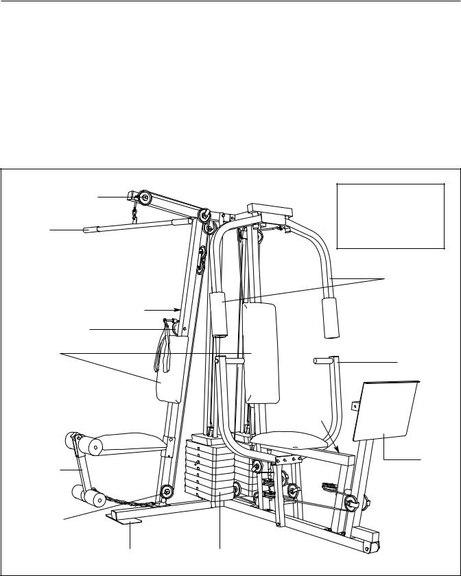
Before reading further, please review the drawing below and familiarize yourself with the parts that are labeled.
High Pulley Station |
Assembled |
|
|
Dimensions: |
|
|
Height: |
78 in./198 cm |
Lat Bar |
Width: |
64 in./163 cm |
|
Length: |
70 in./178 cm |
|
|
Butterfly Arms |
Decal |
|
|
Ab Pulley Station |
|
|
Backrests |
|
Press Arm |
|
|
|
|
Decal |
|
|
|
Leg Press |
Leg Lever |
|
Plate |
|
|
|
Low Pulley |
|
|
Station |
|
|
Foot Plate |
Weight Stacks |
|
|
4 |
|

ASSEMBLY
Make Assembly Easier for Yourself
Everything in this manual is designed to ensure that the weight system can be assembled successfully by anyone. Before beginning assembly, make sure to read the information on this page; this brief introduction will save you much more time than it takes to read it.
Assembly Requires Two Persons
For your convenience and safety, assemble the weight system with the help of another person.
Set Aside Enough Time
Due to the many features of the weight system, the assembly process will require several hours. By setting aside plenty of time and by deciding to make the task enjoyable, assembly will go smoothly. You may want to assemble the weight system over a couple of evenings.
Select a Location for the Weight System
Because of its weight and size, the weight system should be assembled in the location where it will be used. Make sure that there is enough room to walk around the weight system as you assemble it.
How to Unpack the Box
To make assembly as easy as possible, we have divided the assembly process into four stages. The parts needed for each stage are found in individual bags. Important: Wait until you begin each stage to open the parts bag for that stage. Place all parts of the weight system in a cleared area and remove the packing materials. Do not dispose of the packing materials until assembly is completed.
Make sure you have the following tools:
• Two (2) adjustable wrenches
• One (1) standard screwdriver
• One (1) phillips screwdriver
• One (1) rubber mallet
• You will also need grease or petroleum jelly, a small amount of soapy water, and clear tape or masking tape.
Note: Assembly will be more convenient if you have a socket set, a set of open-end or closed-end wrenches, or a set of ratchet wrenches.
How to Identify Parts
To help you identify the small parts used in assembly, we have included a PART IDENTIFICATION CHART in the center of this manual. Place the chart on the floor and use it to easily identify parts during each assembly step. Note: Some small parts may have been pre-attached. If a part is not in the parts bag, check to see if it has been pre-attached.
How to Orient Parts
As you assemble the weight system, make sure that all parts are oriented exactly as shown in the drawings.
Tightening Parts
Tighten all parts as you assemble them, unless instructed to do otherwise.
Questions?
If you have questions after reading the assembly instructions, see the front cover of this manual.
The Four Stages of the Assembly Process
|
|
Frame Assembly—You will begin by assembling |
Cable Assembly—During this stage you will |
the base and the uprights that form the skeleton of |
attach the cables and pulleys that connect the |
the weight system. |
arms to the weights. |
Arm Assembly—During this stage you will |
Seat Assembly—During the final stage you will |
assemble the arms and the leg lever. |
assemble the seats and the backrests. |
|
|
5
|
Frame Assembly |
1 |
|
|
|
|
|
|
|
|
|
|
|
1. |
|
|
|
55 |
20 |
|
Before beginning assembly, make sure you |
|
|
|
|
|
|
|
|
|
|
|
|
|
|
understand the information in the box on |
|
|
20 |
|
13 |
|
page 5. Refer to the PART IDENTIFICATION |
14 |
|
|
||
|
|
|
|
|
||
|
CHART in the center of this manual for help |
|
|
|
|
|
|
|
|
|
|
|
|
|
identifying small parts. |
|
|
|
|
|
|
|
|
|
49 |
40 |
|
|
Locate and open the parts bags labeled |
|
|
|
|
|
|
“FRAME ASSEMBLY.” |
|
|
|
|
49 |
|
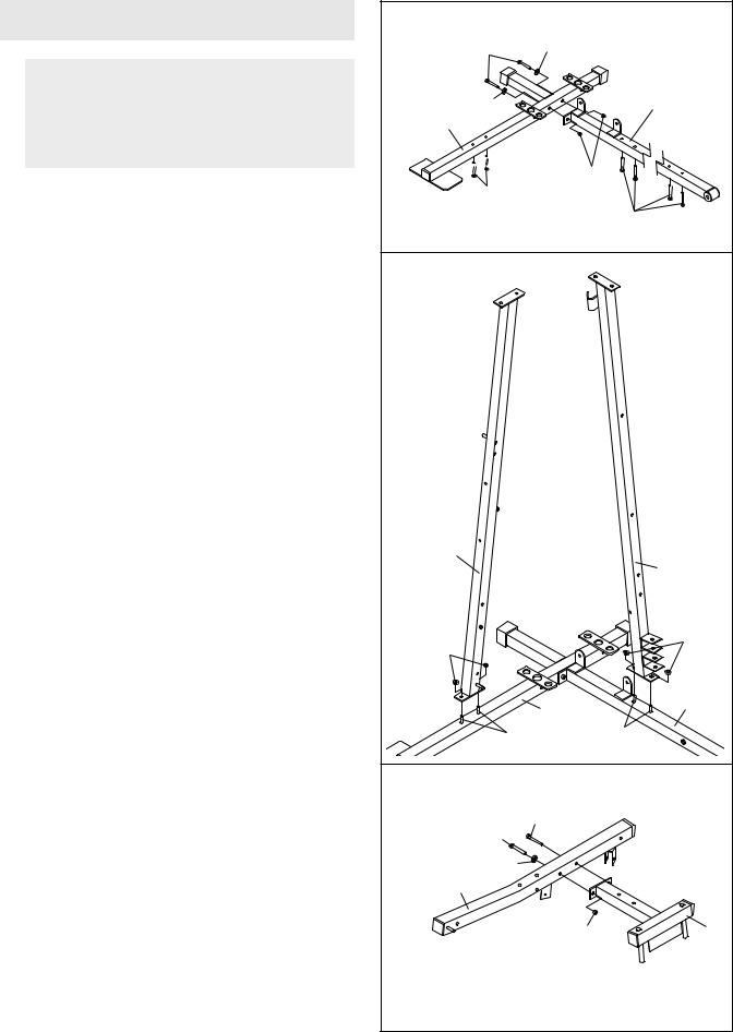
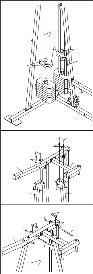
Insert six M8 x 63mm Carriage Bolts (49) up |
2 |
|
|
|
|
|
through the Press Base (13) and the Weight Base |
|
|
|
|
|
|
(14). |
|
|
|
|
|
|
Attach the Press Base (13) to the Weight Base |
|
|
|
|
|
|
(14) with two M8 x 67mm Bolts (55), two M8 |
|
|
|
|
|
|
Washers (20), and two M8 Nylon Locknuts (40). |
|
|
|
|
|
|
Do not tighten the Locknuts yet. |
|
|
|
|
|
2. Slide the Ab Upright (1) onto the indicated M8 x |
|
|
|
|
|
|
|
63mm Carriage Bolts (49) in the Weight Base |
|
|
|
|
|
|
(14). Hand tighten two M8 Nylon Locknuts (40) |
|
|
|
|
|
|
onto the Carriage Bolts. Do not tighten the |
|
|
|
|
|
|
Locknuts yet. |
|
|
|
|
|
|
Slide the Leg Press Upright (4) onto the indicated |
|
|
|
|
|
|
M8 x 63mm Carriage Bolts (49) in the Press Base |
1 |
|
|
|
|
|
(13). Hand tighten two M8 Nylon Locknuts (40) |
|
|
|
4 |
|
|
onto the Carriage Bolts. Do not tighten the |
|
|
|
|
|
|
Locknuts yet. |
|
|
|
|
|
|
|
40 |
|
|
|
40 |
|
|
|
|
|
|
|
|
|
|
|
|
14 |
13 |
|
|
|
|
|
49 |
|
|
|
|
|
49 |
|
|
3. Attach the Butterfly Frame (3) to the Top Frame |
3 |
|
|
|
|
|
|
(2) with an M8 x 67mm Bolt (55), an M8 Washer |
|
|
|
|
|
|
|
|
|
|
|
|
|
(20), and an M8 Nylon Locknut (40). Do not |
|
|
|
43 |
|
|
tighten the Locknut yet. Insert an M8 x 69mm |
|
|
55 |
|
|
|
|
|
|
|
||
|
Shoulder Bolt (43) into the Top Frame and |
|
|
|
|
|
|
Butterfly Frame from the side shown. |
|
|
20 |
|
|
|
|
|
|
|
|
|
|
|
|
2 |
|
|
|
|
|
|
|
|
40 |
3 |
|
|
6 |
|
|
|
|
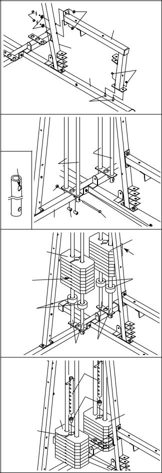
4. Slide the Front Seat Frame (8) onto the indicated |
4 |
|
|
|
40 |
|
M8 x 63mm Carriage Bolts (49) in the Press Base |
55 |
|
|
|
||
|
|
|
|
|||
(13). Hand tighten two M8 Nylon Locknuts (40) |
|
|
|
|
|
|
|
|
|
|
|
8 |
|
onto the Carriage Bolts. Do not tighten the |
|
20 |
|
|
|
|
Locknuts yet. |
|
|
|
|
|
|
Attach the other end of the Front Seat Frame (8) |
|
|
|
4 |
|
|
to the Leg Press Upright (4) with two M8 x 67mm |
|
|
|
|
|
|
Bolts (55), two M8 Washers (20), and two M8 |
|
|
|
|
13 |
40 |
Nylon Locknuts (40). Do not tighten the |
|
|
|
|
|
|
Locknuts yet. |
|
|
|
|
|
|
|
|
|
|
|
49 |
|
5. Insert two Weight Guides (23) into one of the |
5 |
|
|
|
|
|
brackets on the Weight Base (14). Make sure the |
|
|
|
|
|
|
Weight Guides are oriented with the tall holes |
|
|
|
|
|
|
near the top (see the inset drawing). Attach the |
|
|
|
|
|
|
lower ends of the Weight Guides to the Base with |
|
Tall |
|
|
23 |
|
an M8 x 152mm Bolt (67), two 13mm x 19mm |
|
|
|
|
||
|
23 |
|
|
|
||
Spacers (69), and an M8 Nylon Locknut (40). Do |
|
Hole |
|
|
|
|
not overtighten the Locknut. |
|
|
|
|
|
|
Attach the other Weight Guides (23) in the |
|
|
40 |
|
|
|
same manner. |
|
|
|
|
|
|
|
|
|
|
|
|
|
|
|
|
14 |
69 |
|
67 |
6. Slide a Weight Bumper (27) onto each of the |
6 |
|
|
|
|
90 |
Weight Guides (23). |
|
|
|
|
||
Slide eight Weights (90) onto each set of Weight |
|
|
90 |
|
|
Pin |
|
|
|
|
|
Grooves |
|
Guides (23). Make sure that the pin grooves |
|
|
|
|
|
|
|
|
|
|
|
|
|
are on the indicated side of each stack of |
|
Pin |
|
|
|
27 |
Weights. |
|
|
|
|
||
|
|
Grooves |
|
|
|
|
|
|
27 |
|
|
|
|
|
|
|
|
23 |
23 |
|
|
|
|
|
|
|
|
7. Press a Weight Tube Bumper (26) into each |
7 |
|
|
|
|
|
Weight Tube (25). |
|
|
|
25 |
|
|
|
|
|
|
|
||
Insert a Weight Tube (25) into each stack of |
|
|
|
|
|
|
Weights (90). Make sure that the pins on the |
|
|
|
|
26 |
|
Weight Tubes are in the pin grooves in the |
|
|
|
|
|
|
upper Weights. |
|
|
90 |
|
|
90 |
|
|
|
|
|
||
|
|
|
|
|
|
|
|
|
Groove |
|
|
|
|
|
7 |
|
|
|
|
|
8. |
Lubricate the insides of the indicated holes in the |
8 |
|
|
|
|
|
|
|
Top Weights (24) with the included grease. Slide |
|
|
|
|
|
|
|
|
|
|
|
|
|
|
|
|
|
a Top Weight onto each set of Weight Guides |
|
|
|
|
|
|
|
|
(23). |
|
|
|
|
|
|
|
|
|
|
|
|
|
|
23 |
|
|
|
|
|
|
|
|
24 |
Lubricate |
|
|
|
|
|
|
|
|
|
|
|
|
|
|
|
|
|
23 |
|
|
Lubricate |
|
|
|
|
|
|
9. |
Attach the Top Frame (2) to the Ab Upright (1) |
9 |
|
|
|
|
|
|
|
with two M8 x 67mm Bolts (55), two M8 Washers |
|
|
|
|
|
|
55 |
|
(20), and two M8 Nylon Locknuts (40). Do not |
|
|
|
|
20 |
|
|
|
tighten the Locknuts yet. |
|
|
55 |
|
|
||
|
|
|
|
|
|
|
|
|
|
Attach the Butterfly Frame (3) to the Leg Press |
|
20 |
|
|
|
|
3 |
|
Upright (4) with two M8 x 67mm Bolts (55), two |
2 |
|
|
|
|
||
|
M8 Washers (20), and two M8 Nylon Locknuts |
|
|
|
|
|
|
|
|
(40). Do not tighten the Locknuts yet. |
|
|
|
|
|
|
|
|
|
|
1 |
|
|
40 |
40 |
4 |
10. |
Attach the upper ends of one set of Weight |
10 |
|
|
|
|
|
|
|
Guides (23) to the Top Frame (2) with an M8 x |
|
|
|
|
|
69 |
|
|
|
|
|
|
40 |
|
||
|
152mm Bolt (67), two 13mm x 19mm Spacers |
|
|
|
|
|
|
|
|
(69), and an M8 Nylon Locknut (40). |
40 |
|
|
69 |
|
|
23 |
|
Attach the upper ends of the other set of |
|
|
|
|
|
67 |
|
|
|
|
|
|
|
|
||
|
Weight Guides (23) to the Top Frame (2) in the |
2 |
|
|
|
|
|
|
|
same manner. |
|
|
|
|
|
|
|
|
|
|
|
|
|
|
|
|
|
Tighten the M8 Nylon Locknuts (40) used in |
|
|
|
|
67 |
|
|
|
steps 1–10. |
|
|
|
|
|
|
|
|
|
|
|
|
|
23 |
|
|
|
|
8 |
|
|
|
|
|
|
|
ARM ASSEMBLY |
11 |
|
|
|
|
|
|
|
|
|
|
|
|
|
|
|
|
10 |
|
|
40 |
|
11. |
Locate and open the parts bag labeled “ARM |
|
|
20 |
|
|
|
|
ASSEMBLY.” |
|
|
|
|
|
|
|
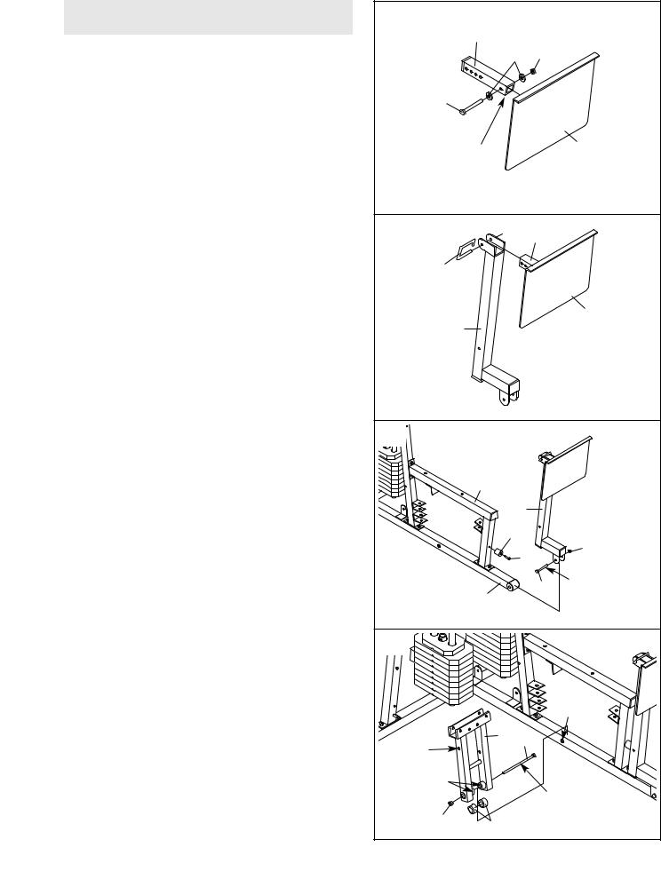
Attach the Leg Press Plate (11) to the Adjustment |
62 |
|
|
|
|
|
|
Tube (10) with an M8 x 60mm Bolt (62), two M8 |
|
|
|
|
|
|
|
Washers (20), and an M8 Nylon Locknut (40). |
|
|
|
|
|
|
|
Make sure that the Leg Press Plate and |
|
Obtuse |
|
|
|
11 |
|
Adjustment Tube are oriented as shown. |
|
|
|
|
||
|
|
|
Angle |
|
|
|
|
12. |
Attach the Adjustment Tube (10) to the Leg Press |
12 |
|
|
|
|
|
|
Arm (9) with the Lock Pin (73). |
|
|
10 |
|
||
|
|
|
|
|
|||
|
|
|
|
|
|
||
|
|
73 |
|
|
|
|
|
|
|
|
9 |
|
|
|
11 |
|
|
|
|
|
|
|
|
13. |
Attach the Leg Press Bumper (53) to the Front |
13 |
|
|
|
|
|
|
Seat Frame (8) with the M5 x 25mm Tap Screw |
|
|
|
|
|
|
|
(72). |
|
|
|
|
|
|
|
Lubricate the M10 x 80mm Bolt (71) with grease. |
|
8 |
|
|
|
|
|
Attach the Leg Press Arm (9) to the Press Base |
|
|
9 |
|
|
|
|
(13) with the Bolt and an M10 Nylon Locknut (42). |
|
|
|
|
|
|
|
Do not overtighten the Locknut; the Leg Press |
|
|
53 |
|
|
|
|
Arm must be able to pivot easily. |
|
|
|
|
42 |
|
|
|
|
72 |
|
|||
|
|
|
|
|
|||
|
|
|
|
|
|
||
|
|
|
13 |
|
|
71 |
Lubricate |
|
|
|
|
|
|
||
|
|
|
|
|
|
|
|
14. |
Press a 25mm x 22mm Plastic Bushing (54) onto |
14 |
|
|
|
|
|
|
each welded spacer on the Press Frame (12). |
|
|
|
|
|
|
|
Slide the Press Frame onto the Press Base (13) |
|
|
|
|
|
|
|
so that the Plastic Bushings are aligned with the |
|
|
|
|
|
|
|
indicated tube. Note: This will be a tight fit. |
|
|
|
|
|
|
|
Make sure that the high hole is on the side |
|
|
|
|
|
Tube |
|
shown. |
|
|
12 52 |
|
|
|
|
Lubricate the M10 x 195mm Bolt (52) with |
High |
|
|
|
|
|
|
Hole |
|
|
|
|
|
|
|
grease. Attach the Press Frame (12) to the Press |
Welded |
|
|
|
|
13 |
|
Base (13) with the Bolt and an M10 Nylon |
|
|
|
|
||
|
Locknut (42). Do not overtighten the Locknut; |
Spacers |
|
|
|
Lubricate |
|
|
the Press Frame must be able to pivot easily. |
42 |
|
|
|
|
|
|
|
54 |
|
|
|
||
|
|
|
|
|
|
||
|
|
9 |
|
|
|
|
|
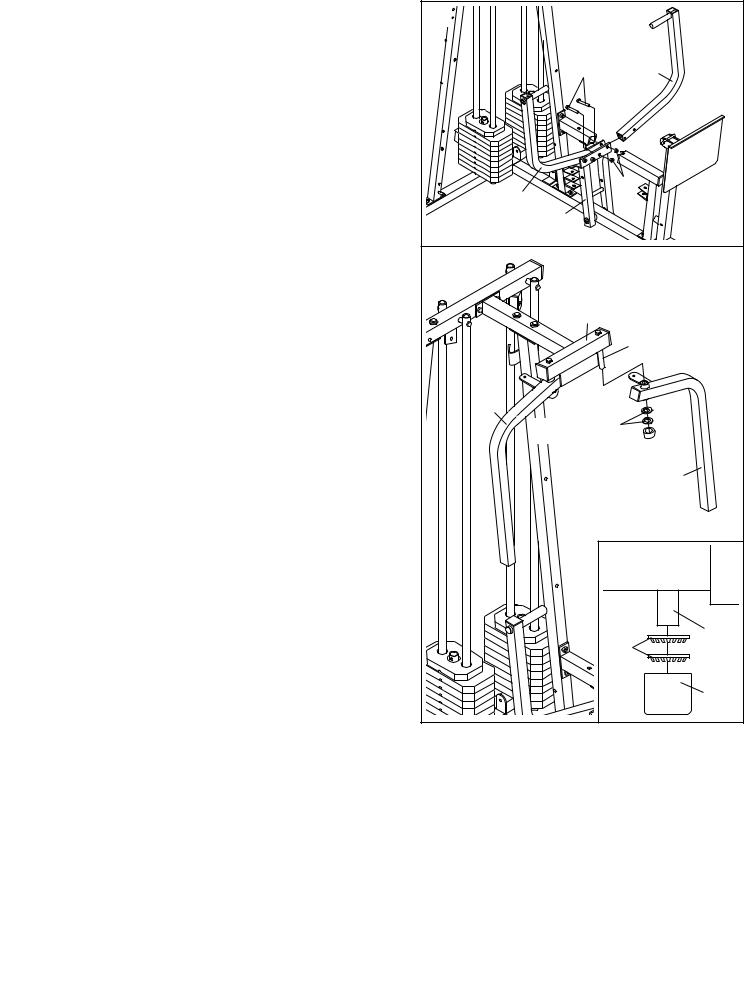
15. Attach a Press Arm (7) to one side of the Press |
15 |
|
|
|
|
|
Frame (12) with two M8 x 63mm Bolts (39) and |
|
|
|
|
|
|
|
|
|
|
|
|
|
two M8 Nylon Locknuts (40). |
|
|
|
|
|
|
Attach the other Press Arm (7) to the Press |
|
|
39 |
|
7 |
|
Frame (12) in the same manner. |
|
|
|
|
|
|
|
|
7 |
|
40 |
|
|
|
|
|
|
|
|
|
|
|
|
12 |
|
|
|
16. Lubricate both axles on the Butterfly Frame (3). |
16 |
|
|
|
|
|
|
|
|
|
|
|
|
Identify the Right Fly Arm (5) and the Left Fly Arm |
|
|
|
|
|
|
(6). |
|
|
3 |
|
|
|
Slide the Left Fly Arm (6) onto the indicated axle. |
|
|
|
|
|
|
|
|
|
Lubricate Axle |
|||
Note: Do not to confuse the Left Fly Arm with |
|
|
|
|||
|
|
|
|
|
|
|
the Right Fly Arm (5). Make sure that the upper |
|
|
|
|
|
|
end of the Left Fly Arm is behind the indicated |
|
|
|
|
|
|
bracket on the Butterfly Frame (3). |
5 |
|
|
|
|
|
|
|
|
45 |
|
|
|
IMPORTANT NOTE: Before assembling the |
|
|
Bracket |
|
|
|
25mm Retainers (45) used in this step, make |
|
|
|
|
46 |
|
sure that you thoroughly understand the step. |
|
|
|
|
6 |
|
The Retainers can be assembled only once. If |
|
|
|
|
|
|
they must be removed, you will need to order |
|
|
|
|
|
|
new Retainers. |
|
|
|
|
|
|
Tap two 25mm Retainers (45) and a 25mm |
|
|
|
|
|
|
Round Outer Cap (46) onto the axle. Make sure |
|
|
|
|
|
|
that the teeth on the Retainers bend toward |
|
|
|
|
|
|
the Round Outer Cap, as shown in the inset |
|
|
|
|
|
|
drawing. |
|
|
|
|
|
|
Attach the Right Fly Arm (5) in the same man- |
|
|
|
45 |
|
Axle |
|
|
|
|
|
||
ner. |
|
|
|
|
|
|
|
|
|
|
|
|
46 |
|
10 |
|
|
|
|
|
17. Wet the lower end of the Left Fly Arm (6) with |
17 |
|
|
soapy water. Slide a Large Pad (22) onto the Left |
|
|
|
|
|
|
|
Fly Arm. |
|
|
|
Repeat this step with the Right Fly Arm (5). |
5 |
|
6 |
|
|
|
|
CABLE ASSEMBLY |
|
|
22 |
18 |
|
|
|
|
|
|
|
18. Locate and open the parts bags labeled |
|
|
|
“CABLE ASSEMBLY,” “CABLES,” and |
|
|
|
“PULLEYS.” |
|
|
|
During steps 19 through 49, refer to the CABLE |
|
|
|
DIAGRAMS on pages 26 and 27 of this manual |
|
|
|
to verify proper cable routing. Before beginning |
|
|
|
this section, fully unwind the five cables and iden- |
|
|
|
tify the cables by comparing the lengths and the |
|
|
|
ends. The approximate length of each cable, in |
|
|
|
inches, is listed after the key number in the draw- |
|
|
|
ing. |
|
|
|
IMPORTANT: While assembling the cables, do |
|
|
|
not overtighten the bolts and locknuts attach- |
|
|
87—72” |
ing the pulleys; the pulleys must be able to |
|
|
|
|
|
|
|
turn freely. |
|
|
89—82” |
|
|
|
|
|
|
85—100” |
|
|
|
86—109” |
|
|
88—238” |
|
|
19. Identify the Butterfly Cable (89)—this is the |
19 |
|
|
second shortest Cable. Attach one end of the |
|
|
|
|
|
|
|
Butterfly Cable to the Right Fly Arm (5) with an |
|
|
|
M8 x 22mm Shoulder Bolt (51) and an M8 Nylon |
|
|
|
Locknut (40). Make sure the flat edge of the |
|
|
|
Cable is against the Fly Arm. |
|
|
51 |
|
|
89 |
|
|
|
5 |
40 |
|
Flat |
|
|
|
Edge |
|
|
|
11 |
|
|
 Loading...