


WCY060G1
Trane WCY060G1, WCY048G1, WCY042G1, WCY024G1, WCY036G1 User Manual
...
IMPORTANT — This Document is customer property and is to remain with this unit. Please return to service information pack upon completion of work.
ALL phases of this installation must comply with
NATIONAL, STATE AND LOCAL CODES
HAZARDOUS VOLTAGE - DISCONNECT POWER BEFORE SERVICING
WARNING:
Single Package Heat Pump
13-14 SEER Convertible
2 - 5 Ton
Model:
WCY024G1
WCY030G1
WCY036G1
WCY042G1
WCY048G1
WCY060G1
INSTALLATION
OPERATION
MAINTENANCE
BAYLIFT002A
LIFTING LUG KIT
Since The Trane Companyhas a policy of continuous product and product data
improvement, it reserves the right to change design and specification without notice.
All phases of this installation must comply with the NATIONAL,
STATE & LOCAL CODES. In the absence of local codes, the
installation must conform with National Electric Code -- ANSI/
NFPA 70 or "LATEST REVISION."
WCY-IOM-1D
18-BB33D8-5
Indicates a potentially haz-
result in death or serious injury.
WARNING:
CAUTION:
result in minor or moderate injury. It may also
be used to alert against unsafe practices
and where property-damage-only accidents
could occur.
▲
▲
Warnings and Cautions appear at appro-
priate locations throughout this manual.
Read these carefully.
NOTICE
ardous situation which, if not avoided, could
Indicates a potentially haz-
ardous situation which, if not avoided, may
© 2002 American Standard Inc. All rights reserved
07/02
Page 2
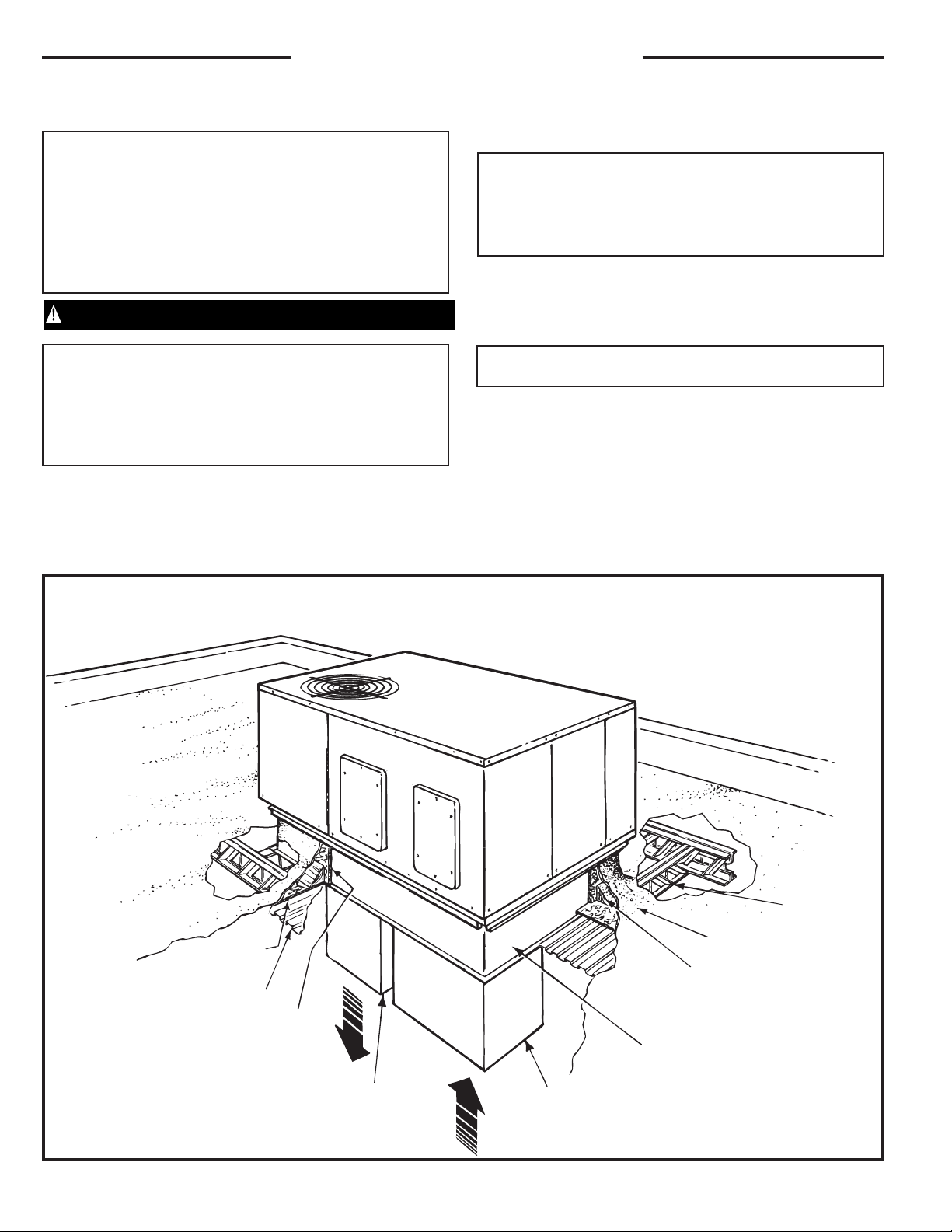
TYPICAL ROOFTOP INSTALLATION WITH FULL PERIMETER CURBS
(WCY024-060G Models)
GENERAL INFORMATION
IMPORTANT: Read this entire manual before beginning instal-
lation procedures.
SAFETY NOTICE. THIS INFORMATION IS INTENDED FOR
USE BY INDIVIDUALS POSSESSING ADEQUATE BACK-
GROUNDS OF ELECTRICAL AND MECHANICAL EXPERI-
ENCE. ANY ATTEMPT TO REPAIR A CENTRAL AIR CONDI-
TIONING PRODUCT MAY RESULT IN PERSONAL INJURY
AND/OR PROPERTY DAMAGE. THE MANUFACTURER OR
SELLER CANNOT BE RESPONSIBLE FOR THE INTERPRE-
TATION OF THIS INFORMATION, NOR CAN IT ASSUME
LIABILITY IN CONNECTION WITH ITS USE.
HAZARDOUS VOLTAGE - DISCONNECT POWER BEFORE SERVICING
WARNING:
IMPORTANT: RECONNECT ALL GROUNDING DEVICES.
ALL PARTS OF THIS PRODUCT CAPABLE OF CONDUCTING
ELECTICAL CURRENT ARE GROUNDED. IF GROUNDING
WIRES, SCREWS, STRAPS, CLIPS NUTS OR WASHERS
USED TO COMPLETE A PATH TO GROUND ARE REMOVED
FOR SERVICE. THEY MUST BE RETURNED TO THIER ORIGI-
NAL POSITION AND PROPERLY FASTENED.
IMPORTANT: ALL POWER LEGS MAY NOT BE BROKEN BY
CONTACTORS. SEE WIRING DIAGRAM ON UNIT CONTROL
BOX COVER.
BEFORE STARTING THE COMPRESSOR, THE CRANKCASE
HEATER SHOULD BE ENERGIZED FOR EIGHT HOURS
Read this manual carefully before attempting to install, operate, or
perform maintenance on this unit. Installation and maintenance
should be performed by qualified service technicians only.
NOTE: "Warnings" and "Cautions" appear at appropriate
places in this manual. Your personal safety and the proper
operation of this air conditioning product require that you follow
them carefully. The manufacturer assumes no liability for
installations or servicing performed by unqualified personnel.
INSPECTION
1. Check for damage after the unit is unloaded. Report promptly,
to the carrier, any damage found to the unit. Do not drop the unit.
IMPORTANT: The use of "spreader bars" is required when
hoisting the unit ( to prevent damage to sides and top ).
2. Check the unit's nameplate to determine if the unit is correct for
the intended application. The power supply must be adequate
for both the unit and all accessories.
3. Check to be sure the refrigerant charge has been retained during
shipment. Access to 1/4" flare pressure taps may be gained by
removing the furnace compartment access panel.
1
ROOF INSULATION
ROOF DECK
FIELD SUPPLIED
RIGID INSULATION
SUPPLY AIR
DUCT
RETURN AIR
DUCT
ROOF MOUNTING
CURB
FIELD SUPPLIED
CANT STRIP
FIELD SUPPLIE
D
SUPPORTS
AT EACH END
OF CURB
ROOFING
Page 3
ROOF INSULATION
ROOF DECK
FIELD SUPPLIED
RIGID INSULATION
SUPPLY AIR
DUCT
RETURN AIR
DUCT
ROOF MOUNTING
CURB
FIELD SUPPLIED
CANT STRIP
FIELD SUPPLIE
D
SUPPORTS
AT EACH END
OF CURB
ROOFING
SEE NOTE 1
SEE NOTE 2
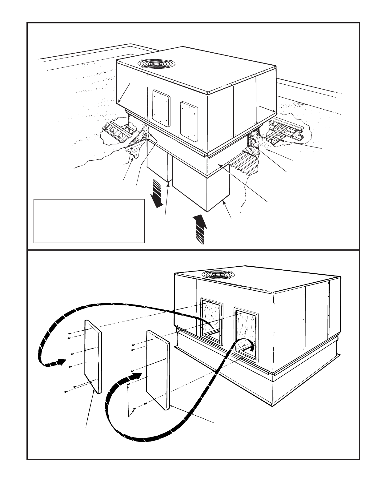
CONVERTING HORIZONTAL TO DOWNFLOW
TYPICAL ROOFTOP INSTALLATION WITH BAYCURB030A
(WCY024-060G Models)
NOTE
SUPPLY OPENING
1. REMOVE THE SCREW NEAREST TO THE
OPENING AND PULL THE PANEL FIRMLY
TOWARD THE OUTSIDE OF THE UNIT TO
DISENGAGE THE BACK ATTACHMENT.
RETURN OPENING
2. REMOVE RIGHT HAND SCREW AND
MOVE PANEL TO THE RIGHT OR
REMOVE BOTH SCREWS.
3. REMOVE EXTERIOR GASKET MATERIAL.
2
3
NOTE 1: The WCY036-042G Models extend
out past this end of the curb only.
NOTE 2: Only the WCY048-060G Models
extend past both the end and the
side of the curb as illustrated
HORIZONTAL SUPPLY
AIR COVER
HORIZONTAL RETURN
AIR COVER
SHEET METAL
SCREWS
Page 4
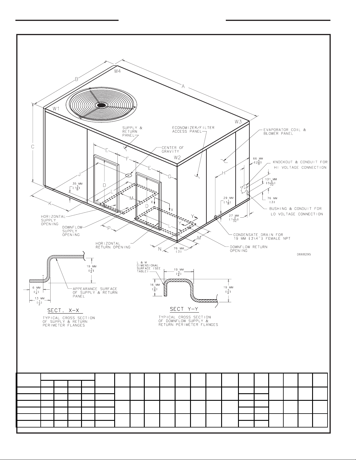
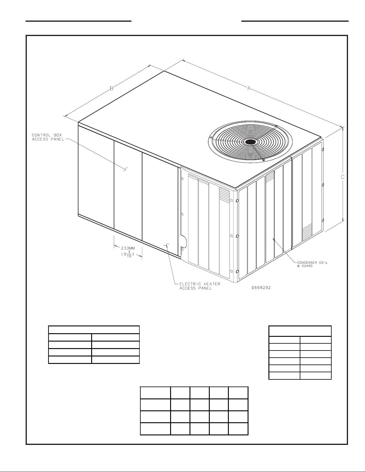
DIMENSIONAL DATA
4
MODEL
CORNER WEIGHT(LBS)
UNIT
WEIGHT
ABCDEFG H JKLMNP
W1 W2 W3 W4
WCY024G 79 74 74 104 331
56-1/2 36 29-3/16 18-9/16 11-1/16 6-9/16 6-13/16 17
21 25-3/8
17-1/2 10 3 4-7/16
WCY030G 82 64 86 110 342 21 24-3/8
WCY036G 110 82 88 118 398
64 36 29-1/ 16 18-9/16 11-1/16 6-9/16 11-1/8 17
19-1/4 27-1/2
17-1/2 10 3 8-3 /4
WCY042G 110 82 88 118 398 19-1/4 27-1/2
WCY048G 149 104 117 134 504
65-1/8 45 33-1/8 21-1/16 15-1/16 4-15/16 9-1/8 21-15/16
24-1/4 28-1/2
20 14 3-1/2 8-5/16
WCY060G 126 98 121 157 502 20 28
WCY024-060G OUTLINE - BACK
Page 5
DIMENSIONAL DATA
5
From Dwg. 21D664
MODEL A B C D
WCY024G
WCY030G
56-1/2 36 29-3/16 12-15/1
6
WCO36G
WCY042G
64 36 29-3/16 14-1/2
WCY048G
WCY060G
65-1/8 45 33-3/8 14-13/1
6
RECOMMENDED SERVICE CLEARANC
E
BACK * 6.0"
LEFT SIDE 30.0"
RIGHT SIDE 24.0"
FRONT SIDE 30.0"
* 18" WITH FRESH AIR ACCESSORY
* 30" WITH EC ONOMI ZE R
CLEARANCE TO
COMBUSTIBLE MATERIA
L
BOTTOM 0.0"
BACK 1.0"
LEFT SIDE 6.0"
RIGHT SIDE 6.0"
FRONT SIDE 12.0"
TOP 36.0"
WCY024-060G OUTLINE - FRONT
Page 6
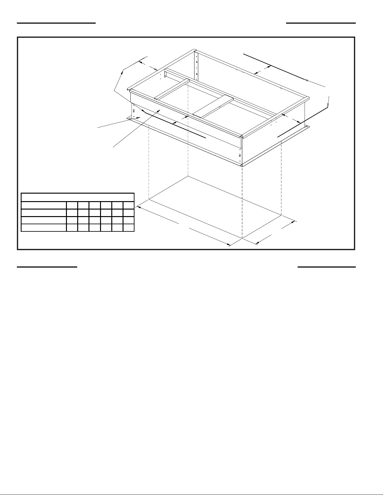
REQUIRED CLEARANCE FOR UNIT INSTALLATION
AND ROOF PENETRATION HOLE SIZE REQUIRED
LOCATIONS AND RECOMMENDATIONS
These units are designed for outdoor installation. For proper instal-
lation, the following recommendations must be considered.
NOTE: Unit shipped for horizontal installation. Convert to
downflow per instruction.
The discharge air from the condenser fans must be unrestricted for
a minimum of 3 feet above the unit.
Roof Mounting Curb (field assembled BAYCURB030A and
BAYCURB033A, BAYCURB034A) or a field fabricated curb must be
in place before unit is hoisted to the roof.
Roof Mounting Curb (frame) must be installed on a flat, level
section of the roof (max. of 1/4" per foot pitch), providing a level
mounting surface for the unit. In addition, provide sufficient
height above the roof to prevent water from entering unit.
In locations where deep snows are encountered,RAlSE THE UNlT
A MINIMUM OF 12" OFF THE ROOF, DECK OR SLAB—the chance
of the coil being blocked with snow will be reduced. The water that
occurs during the defrost has a better chance of flowing from the
vicinity of the unit.
Roof Mounting Curb used with WCY—F models is approximately
14" high. This is normally sufficient height to prevent snow blockage
and additional clearance is not necessary.
AVOID LOCATING THE UNIT WHERE SNOW TENDS TO DRIFT.
This will reduce the times when it is necessary for the customer to
remove the snow from around the unit. MAKE CERTAIN THE
CUSTOMER KNOWS THAT SNOW ACCUMULATIONS SHOULD
BE REMOVED FROM THE SIDES OF THE UNIT FOR BEST
EFFICIENCY.
A snow drift barrier may be installed around the unit to prevent a
build up of snow on the sides of the unit. The barrier should be of
sufficient distance from the unit to prevent restriction of airflow to
and from unit.
LOCATE THE UNIT SO THAT THE WATER VAPOR THAT DIS-
CHARGES UPWARD DURING DEFROST DOES NOT CONDENSE
ON WINDOWS AND FOG THEM OR CAUSE ICICLES TO FORM
ON OVERHANGS.
1. Be sure the mounting curb spans structural members (trusses)
of the roof, thereby providing sufficient support for weight of the
unit, curb and duct(s) plus any accessories (factory or field
installed). See Figures 1, 2, 3, 4, 5, 6, 7, 8, 9,10,11 and 12.
NOTE: If any internal accessories are to be added to the unit it
should be done at the shop if at all practical.
2. Unit should be positioned so Roof-Run-Off water does not pour
directly on unit.
6
E
F
HOLE IN ROOF
WOOD NAILER
SIDE RAIL
SERVICE
CLEARANCE
LINES
SERVICE
CLEARANCE
LINES
A
B
C
D
SUPPLY AIR
RETURN AIR
SERVICE CLEARANCE & PENETRATION DIMENSIONS
MODEL NO. A B C D E F
WCY024-030G 30" 30" *12" 24" 36" 25
"
WCY036-042G 30" 30" *12" 30" 44" 25
"
WCY048-060G 42" 30" *12" 36" 50" 25
"
* 18" WITH FRESH AIR ACCESSORY
* 30" WITH ECONOMIZER
 Loading...