


WSHP
Table of contents
 Loading...
Installation, Operation,
and Maintenance
Water Source Heat Pump
Axiom™ High Efficiency Vertical Stack — GET
¾-3Tons-60Hz
SAFETY WARNING
Only qualified personnel should install and service the equipment. The installation, starting up, and servicing of
heating, ventilating, and air-conditioning equipment can be hazardous and requires specific knowledge and training.
Improperly installed, adjusted or altered equipment by an unqualified person could result in death or serious injury.
When working on the equipment, observe all precautions in the literature and on the tags, stickers, and labels that
are attached to the equipment.
November 2013
WSHP-SVX10B-EN
Warnings, Cautions and Notices
Warnings, Cautions and Notices. Note thatwarnings,
cautions and notices appear at appropriate intervals
throughout this manual. Warnings are provide to alert
installing contractors to potentialhazards that could result
in death or personal injury. Cautions are designed to alert
personnel to hazardous situations that could result in
personal injury, while notices indicate a situation that
could result in equipment or property-damage-only
accidents.
Your personal safety and the proper operation of this
machine depend upon the strict observance of these
precautions.
Read this manual thoroughlybefore operating or servicing
this unit.
ATTENTION: Warnings, Cautions and Notices appear at
appropriate sections throughout this literature. Read
these carefully:
WARNING
CAUTIONs
NOTICE:
Indicates a potentially hazardous
situation which, if not avoided, could
result in death or serious injury.
Indicates a potentially hazardous
situation which, if not avoided, could
result in minor or moderate injury. It
could also be used to alert against
unsafe practices.
Indicates a situationthat could resultin
equipment or property-damage only
Contains Refrigerant!
System contains oil and refrigerant under high
pressure. Recover refrigerant to relieve pressure before
opening the system. See unit nameplate for refrigerant
type. Do not use non-approved refrigerants, refrigerant
substitutes, or refrigerant additives.
Failure to follow proper procedures or the use of nonapproved refrigerants, refrigerant substitutes, or
refrigerant additives could result in death or serious
injury or equipment damage.
Proper Field Wiring and Grounding
Required!
All field wiring MUST be performed by qualified
personnel. Improperly installed and grounded field
wiring poses FIRE and ELECTROCUTION hazards. To
avoid these hazards, you MUST follow requirements for
field wiring installation and grounding as described in
NEC and your local/state electrical codes. Failure to
follow code could result in death or serious injury.
WARNING
WARNING
Important
Environmental Concerns!
Scientific research has shown that certain man-made
chemicals can affect the earth’s naturally occurring
stratospheric ozone layer when released to the
atmosphere. In particular, several of the identified
chemicals that may affect the ozone layer are refrigerants
that contain Chlorine, Fluorine and Carbon (CFCs) and
those containing Hydrogen, Chlorine, Fluorine and
Carbon (HCFCs). Not all refrigerants containing these
compounds have the same potential impact to the
environment.Trane advocates the responsible handling of
all refrigerants-including industry replacements for CFCs
such as HCFCs and HFCs.
Responsible Refrigerant Practices!
Trane believes that responsible refrigerant practices are
important to the environment, our customers, and the air
conditioning industry. All technicians who handle
refrigerants must be certified.The Federal Clean Air Act
(Section 608) sets forth the requirements for handling,
reclaiming, recovering and recycling of certain
refrigerants and the equipment that is used in these
service procedures. In addition, some states or
municipalities may have additional requirements that
must also be adhered to for responsible management of
refrigerants. Know the applicable laws and follow them.
© 2013Trane All rights reserved WSHP-SVX10B-EN
Personal Protective Equipment (PPE)
Required!
Installing/servicing this unit could result in exposure to
electrical, mechanical and chemical hazards.
• Before installing/servicing this unit, technicians
MUST put on all Personal ProtectiveEquipment (PPE)
recommended for the work being undertaken.
ALWAYSrefer to appropriate MSDS sheets and OSHA
guidelines for proper PPE.
• When working with or around hazardous chemicals,
ALWAYS refer to the appropriate MSDS sheets and
OSHA guidelines for information on allowable
personal exposure levels, proper respiratory
protection and handling recommendations.
• If there is a risk of arc or flash, technicians MUST put
on all Personal Protective Equipment (PPE) in
accordance with NFPA 70E or other country-specific
requirements for arc flash protection, PRIOR to
servicing the unit.
Failure to follow recommendations could result in death
or serious injury.
WARNING

Revision Summary
WSHP-SVX10B-EN (15 November 2013)
• WPRD Chassis Model Number change
WSHP-SVX10B-EN (18 June 2013)
• Add ECM motor
Trademarks
Trane and theTrane logo are trademarks or registered
trademarks ofTrane in the United States and other
countries.Trane is a business of Ingersoll Rand. All
trademarks referenced in this document are the
trademarks of their respective owners.
Warnings, Cautions and Notices
WSHP-SVX10B-EN 3

Table of Contents
Model Number Descriptions .............. 5
General Information ..................... 7
Pre-Installation .......................... 8
Dimensions and Weights ................. 9
Installation ............................. 12
Electrical Data .......................... 21
Pre-Start-up ............................ 22
Checklist ............................ 22
Initial Unit Start-up ................... 22
Operating Pressures .................... 23
Start-up ................................ 26
Maintenance ........................... 27
Troubleshooting ........................ 28
Unit Wiring ............................ 30
Warranty ............................... 34
4 WSHP-SVX10B-EN

Model Number Descriptions
Vertical High-Rise Cabinet
WSHP
Digits 1-3: Unit Configuration
GET = High Efficiency Vertical High Rise
Heat Pump
Digit 4: Development Sequence
E = R-410A
Digits 5-7: Nominal Size (Tons)
009=¾Tons
012=1Tons
015=1¼Tons
018=1½Tons
024 = 2Tons
036 = 3Tons
Digit 8: Voltage (Volts/Hz/Phase)
1 = 208/60/1
2 = 230/60/1
7 = 265/60/1
Digit 9: Heat Exchanger
1 = Copper Water Coil
2 = Cupro-Nickel Water Coil
3 = Copper Water Coil with Isolation
Valve and Low Flow Control
4 = Cupro- Nickel Water Coil with
Isolation Valve and Low Flow Control
5 = Copper Water Coil with Isolation
Valve and High Flow Control
6 = Cupro-Nickel Water Coil with Isolation
Valve and High Flow Control
Digit 10: Current Design
Sequence
Digit 11: Refrigeration Circuit
0 = Heating and Cooling Circuit
Digit 12: Blower Configuration
1 = Free Discharge - PSC motor
2 = Ducted Discharge - PSC motor
3 = Free Discharge w/1" Flange -
PSC motor
4 = Free Discharge w/3" Flange -
PSC motor
5 = ECM motor w/o flange
6 = ECM motor w/1" flange
7 = ECM motor w/3" flange
8 = Chassis only/No motor (ECM Control)
9 = Chassis only/No motor (PSC Control)
Digit 13: Freeze Protection
A = 20° freezestat
B = 35° freezestat
Digit 14: Open Digit
0 = Open
S = Special
Digit 15: Supply Air
Arrangement
0 = No Supply Air Arrangement
1 = Back and Front Supply Air
2 = Back and Left Supply Air
3 = Back and Right Supply Air
4 = Front and Left Supply Air
5 = Front and Right Supply Air
6 = Left and Right Supply Air
7 = Back, Front and Right Supply Air
8 = Back, Front and Left Supply Air
9 = Front, Right and Left Supply Air
B = Back Supply Air
L = Left Supply Air
R = Right Supply Air
T =Top Supply Air
F = Front Supply Air
Digit 16: Return Air
Arrangement
0 = No Return Air Door (Field Provided)
1 = Flush with Wall, Acoustic Hinged
Return Air Door with Keyless Entry
2 = Flush with Wall, Acoustic Hinged
Return Air Door with Keylock Entry
Digit 17: Control Types
D = Deluxe 24V Controls
C =Tracer™ ZN510 Controls
Digit 18: Thermostat Sensor
Location
0 = Wall Mounted Location
Digit 19: Fault Sensors
0 = No Fault Sensors
1 = Condensate Overflow Sensor
2 = Filter MaintenanceTimer
3 = Condensate Overflow and Filter
MaintenanceTimer
Digit 20-22: Open Digits
Digit 23: Unit Mounted
Disconnect
0 = No Unit Mounted Switch
C =Toggle Switch Only
D =Toggle Switch with Fuses
Digit 24: Filter Type
1 = 1-inchThrowaway Filter
Digit 25: Acoustic Arrangement
0 = Enhanced Sound Attenuation
1 = Deluxe Sound Attenuation
Digit 26: Factory Configuration
3 = R-410A Cabinet
Digit 27: Paint Color
8 = Polar White
Digit 28: Outside Air Option
0 = No Outside Air
Digit 29: Piping Arrangement
B = Back Riser Location
L = Left Hand Riser Location
R = Right Hand Riser Location
Digit 30: Riser Type
0 = No Riser
L =Type L Riser
M=Type M Riser
Digit 31: Supply Riser
0 = No Riser
B = 1" Dia. Riser with Insulation
C = 1¼" Dia. Riser with Insulation
D = 1½" Dia. Riser with Insulation
E = 2 Dia. Riser with Insulation
F = 2½" Dia. Riser with Insulation
G = 3" Dia. Riser with Insulation
2 = 1" Dia. Riser
3 = 1¼" Dia. Riser
4 = 1½" Dia. Riser
5 = 2" Dia. Riser
6 = 2½" Dia. Riser
7 = 3" Dia. Riser
Digit 32: Return Riser
0 = No Riser
B = 1" Dia. Riser with Insulation
C = 1¼" Dia. Riser with Insulation
D = 1½" Dia. Riser with Insulation
E = 2" Dia. Riser with Insulation
F = 2½" Dia. Riser with Insulation
G = 3" Dia. Riser with Insulation
2 = 1" Dia. Riser
3 = 1¼" Dia. Riser
4 = 1½" Dia. Riser
5 = 2" Dia. Riser
6 = 2½" Dia. Riser
7 = 3" Dia. Riser
Digit 33: Condensate Riser
0 = No Riser
B = 1" Dia. Riser with Insulation
C = 1¼" Dia. Riser with Insulation
D = 1½" Dia. Riser with Insulation
E = 2" Dia. Riser with Insulation
F = 2½" Dia. Riser with Insulation
G = 3" Dia. Riser with Insulation
2 = 1" Dia. Riser
3 = 1¼" Dia. Riser
4 = 1½" Dia. Riser
5 = 2" Dia. Riser
6 = 2½" Dia. Riser
7 = 3" Dia. Riser
WSHP-SVX10B-EN 5

Model Number Descriptions
Digit 34, 35, 36: Riser Length
000 = No Riser
096 = 96" Riser Length
097 = 97" Riser Length
098 = 98" Riser Length
099 = 99" Riser Length
100 = 100" Riser Length
101 = 101" Riser Length
102 = 102" Riser Length
103 = 103" Riser Length
104 = 104" Riser Length
105 = 105" Riser Length
106 = 106" Riser Length
107 = 107" Riser Length
108 = 108" Riser Length
109 = 109" Riser Length
110 = 110" Riser Length
111 = 111" Riser Length
112 = 112" Riser Length
113 = 113" Riser Length
114 = 114" Riser Length
115 = 115" Riser Length
116 = 116" Riser Length
117 = 117" Riser Length
118 = 118" Riser Length
119 = 119" Riser Length
120 = 120" Riser Length
Vertical High-Rise Chassis
WSHP
Digits 1-3: Unit Configuration
GET = High Efficiency Vertical High Rise
Heat Pump (cabinet with blower/motor)
Digit 4: Development Sequence
E = R-410A
Digits 5-7: Nominal Size (Tons)
009=¾Tons
012=1Tons
015=1¼Tons
018=1½Tons
024 = 2Tons
036 = 3Tons
Digit 8: Voltage (Volts/Hz/Phase)
1 = 208/60/1
2 = 230/60/1
7 = 265/60/1
Digit 9: Heat Exchanger
1 = Copper Water Coil
2 = Cupro-Nickel Water Coil
3 = Copper Water Coil with Isolation
Valve and Low Flow Control
4 = Cupro- Nickel Water Coil with Isolation
Valve and Low Flow Control
5 = Copper Water Coil with Isolation
Valve and High Flow Control
6 = Cupro-Nickel Water Coil with Isolation
Valve and High Flow Control
Digit 10: Current Design
Sequence
Digit 11: Refrigeration Circuit
0 = Heating and Cooling Circuit
Digit 12: Blower Configuration
1 = Free Discharge - PSC motor
2 = Ducted Discharge - PSC motor
3 = Free Discharge w/1" Flange -
PSC motor
4 = Free Discharge w/3" Flange -
PSC motor
5 = ECM motor w/o flange
6 = ECM motor w/1" flange
7 = ECM motor w/3" flange
8 = Chassis only/No motor (ECM Control)
9 = Chassis only/No motor (PSC Control)
Digit 13: Freeze Protection
0 = None or Standard
A = 20° Freezestat
B = 35° Freezestat
Digit 14: Open Digit
0 = Open
Digit 15: Supply Air
Arrangement
0 = No Supply Air Arrangement
1 = Back and Front Supply Air
2 = Back and Left Supply Air
3 = Back and Right Supply Air
4 = Front and Left Supply Air
5 = Front and Right Supply Air
6 = Left and Right Supply Air
7 = Back, Front and Right Supply Air
8 = Back, Front and Left Supply Air
9 = Front, Right and Left Supply Air
B = Back Supply Air
L = Left Supply Air
R = Right Supply Air
T =Top Supply Air
F = Front Supply Air
Digit 16: Return Air
Arrangement
0 = No Door (Chassis Only)
1 = Flush with Wall, Acoustic Hinged
Return Air Door with Keyless Entry
2 = Flush with Wall, Acoustic Hinged
Return Air Door with Keylock Entry
Digit 17: Control Types
0 = Basic Controls for WPRD Retrofit
Chassis
D = Deluxe 24V Controls
C =Tracer™ ZN510 Controls
Digit 18: Thermostat Sensor
Location
0 = Wall Mounted Location
Digit 19: Fault Sensors
0= No Fault Sensors
1 = Condensate Overflow Sensor
2 = Filter Maintenance Timer
3 = Condensate Overflow and Filter
MaintenanceTimer
Digit 20-22: Open Digits
Digit 23: Unit Mounted
Disconnect
0 = No Unit Mounted Switch
C = Switch Only
D = Switch with Fuses
Digit 24: Filter Type
1 = 1-inchThrowaway Filter
Digit 25: Acoustic Arrangement
0 = Enhanced Sound Attenuation
1 = Deluxe Sound Attenuation
Digit 26: Factory Configuration
2 = R-410A Chassis
R = WPRD Retrofit Chassis
Digit 27: Paint Color
8 = Polar White
Digit 28: Outside Air Option
0 = No Outside Air
Digit 29: Piping Arrangement
B = Back Riser Location
L = Left Hand Riser Location
R = Right Hand Riser Location
Digit 30: Riser Type
0 = No Riser (Chassis Only)
Digit 31: Supply Riser
0 = No Riser (Chassis Only)
Digit 32: Return Riser
0 = No Riser (Chassis Only)
Digit 33: Condensate Riser
0 = No Riser (Chassis Only)
Digit 34, 35, 36: Riser Length
000 = No Riser (Chassis Only)
6 WSHP-SVX10B-EN

General Information
Blower/Motor
The blower and motor is located inside the unit cabinet.
The blower and motor may be removed from the cabinet
through the chassis opening. After removing the chassis,
the blower assembly is strapped into the unit cabinet
through a single metal, flexible bracket. We refer to this
bracket as a housing belly bracket. After detaching one
screw at the bottom/front edge of the bracket, the housing
and motor are free to be lifted from the fan deck.
Compressor Nameplate
The nameplate for the compressors are located on the
compressor shell.
Controls
A 75 VA transformer is factory supplied on this unit
configuration. See wiring diagram on chassis access panel
for field wiring connection to the 24V mechanical
thermostat.
Deluxe 24V Controls
Units containing the Deluxe 24V control design will
incorporate a microprocessor-based control board.The
Trane microprocessor board is factory wired to a terminal
strip to provide all necessary terminals for field
connection.The deluxe board is equipped with a random
start relay, anti-short cycle timer, brown out protection,
compressor disable, unit safety control, diagnostics and a
generic relay (which may be available for field use). See
p. 14 for diagnostic information.
Power wiring is made at the contactor.The wiring is fed
through the left or right conduittube, and intothe cabinet’s
control box (contactor).
Schrader Connections
Connections for the low and high side of the refrigeration
system are located conveniently on the chassis’ front
beneath a sheet metal plate.
Unit Description
Before shipment, each unit is leak tested, dehydrated,
charged with refrigerant and run tested for proper control
operation.
Unit Nameplate
The unit nameplate is located at the front of the unit. It
includes the unit model number, serial number, electrical
characteristics,refrigerant charge, and otherpertinent unit
data.
Water Connections
½" or ¾" water connections are located on the chassis’s
upper section and clearly labeled for water-in/out hose to
riser hook-up.
Water-to-Refrigerant Coils
The co-axial water-to-refrigerant heat exchanger for the ¾
ton through 3 ton equipment is constructed of copper or
cupro-nickel (option) for the water section and stainless
steel for the refrigeration section.
The heat exchanger is leak tested to assure there is no
cross leakage between the water and refrigerant gas.
ZN510 Controls
Units incorporating the ZN510 control option design will
include a digital LonTalk™ certified control board.The
control board will support such options as: random start
delay, heating/cooling status,occupied/unoccupied mode
and fan/filter status.
Power wiring is made at the contactor.The wiring is fed
through the left or right conduittube, and intothe cabinet’s
control box (contactor). See manual WSHP-IOP-2 for
diagnostic information.
Sound Attenuation
Sound attenuation is applied as a standard feature in the
product design.The enhanced reduction package includes
a heavy gage base plate, and gasket/insulation around the
compressor enclosure.
An optional deluxe sound reduction package is also
available. It includes a heavy gage base plate, gasket and
insulation around the compressor enclosure, and
vibration isolation between the chassis and cabinet. An
additional dampening treatment is applied around the
compressor enclosure to achieve greater acoustical
reductions.
WSHP-SVX10B-EN 7
Pre-Installation
WARNING
Fiberglass Wool!
Product contains fiberglass wool. Disturbing the
insulation in this product during installation,
maintenance or repair will expose you to airborne
particles of glass wool fibers and ceramic fibers known
to the state of California to cause cancer through
inhalation. Glass wool fibers could result in respiratory,
skin or eye irritation.
Jobsite Inspection
Always perform the following checks before accepting a
unit:
1. Verify that the nameplate data matches the data on the
sales order and bill of lading (including electrical data).
2. Verify that the power supply complies with the unit
nameplate specifications.
3. Visually inspect the exterior of the unit, for signs of
shipping damage. Do not sign the bill of lading
accepting the unit(s) until inspection has been
completed. Check for damage promptly after the
unit(s) are unloaded. Once the billof lading is signed at
the jobsite, the unit(s) are now the property of the
SOLDTO party and future freight claims MAY NOT be
accepted by the freight company.
4. Verify that the refrigerant charge has been retained
during shipment by use of gauges. Schrader taps are
located external to the cabinet on the ¾-3 ton
equipment.
5. After assuring that charge has been retained, reinstall
the schrader caps to assure that refrigerant leakage
does not occur.
Jobsite Storage
NOTICE:
Microbial Growth!
Wet interior unit insulation can become an
amplification site for microbial growth (mold), which
may cause odors and damage to the equipment and
building materials. If there is evidence of microbial
growth on the interior insulation, the insulation should
be removed and replaced prior to operating the system.
This unit is intended for indoor useonly.To protect the unit
from damage due to the elements, and to prevent possible
IAQ contaminant sources from growing, the unitshould be
stored indoors. If indoor storage is not possible, the
following provisions for outdoor storage must be met:
1. Place the unit(s) on a dry surface or raise above the
ground to assure adequate air circulation beneath the
unit.
2. Cover the unit(s) with a water proof tarp to protect
them from the elements.
3. Make provisionsfor continuous venting of the covered
units to prevent moisture from standing on the unit(s)
surfaces. Wet interior unit insulation can become an
amplification site for microbial growthwhich has been
determined to be a cause of odors and serious health
related indoor air quality problems.
4. Store refrigeration units (chassis) units in the normal
UP orientation to maintain oil in the compressor.
Cabinet configurations may be stored as crated.
5. Do not stack units.
8 WSHP-SVX10B-EN
Dimensions and Weights
WARNING
Improper Unit Lift!
Test lift unit approximately 24 inches to verify proper
center of gravity lift point. To avoid dropping of unit,
reposition lifting point if unit is not level. Failure to
properly lift unit could result in death or serious injury
or possible equipment or property-only damage.
Table 1. Unit weights
Size
009 135 115
012 135 115
015 175 150
018 175 150
024 225 195
036 225 195
009 88 78
012 107 97
015 112 102
018 117 107
024 174 164
036 190 180
Shipping weight with
pallet (lb)
Cabinet
Chassis
Shipping weight
without pallet (lb)
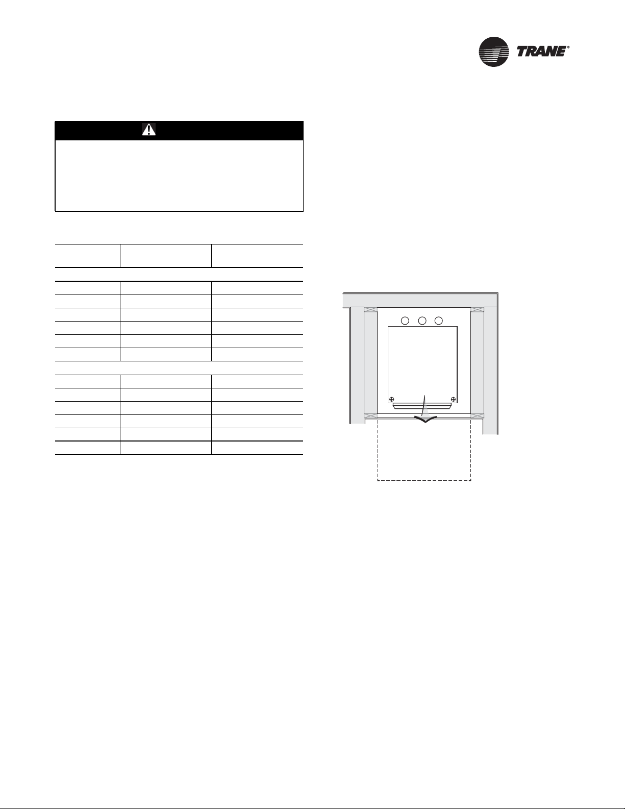
Unit Location and Clearances
Locate the unit in an indoor area.The ambient
temperature surrounding the unit must not be less than
45°F. Do not locate the unit in areas subject to freezing.
Attention should be given to service clearance and
technician safety.The unit chassis should be easily
removed from the cabinet in all applications.There must
be enough space for service personnel to perform
maintenance or repair. Provide sufficient room to make
water, and electrical connection(s). Local and national
codes should be followed in providing electrical power
connections.
Figure 1. Mechanical clearances
RSD
ALLOW 36" (914 mm)
AT UNIT FRONT FOR
CHASSIS REMOVAL
WSHP-SVX10B-EN 9
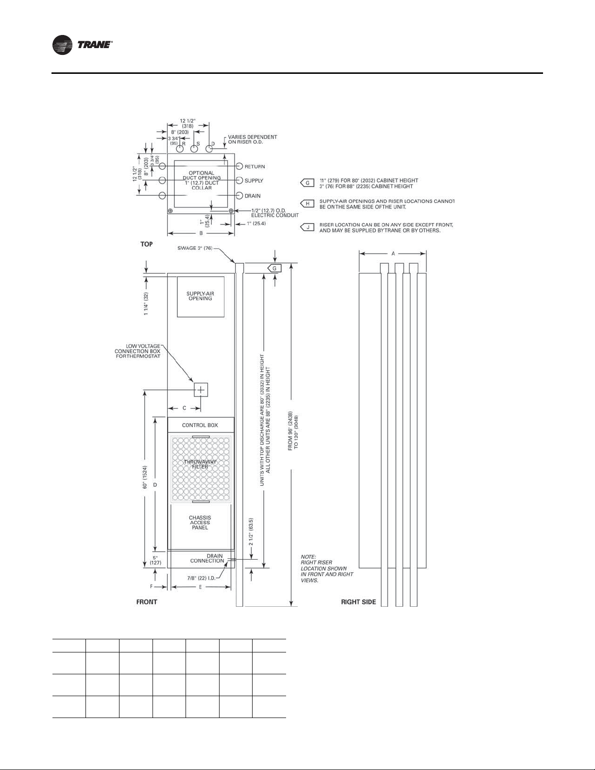
Dimensions and Weights
Figure 2. GET 009-036
Table 2. GET 009-036
GET A B C D E F
009, 012
015-018
024-036
16¼"
(413)
18"
(457)
24"
(610)
10 WSHP-SVX10B-EN
16¼"
(413)
20"
(508)
24"
(610)
8 1/8"
(206)
10"
(254)
12"
(305)
39 1/8"
(994)
40 5/8"
(1032)
49 5/8"
(1260)
14¾"
(375)¾"(19)
18¾"
(476)¾"(19)
22 5/8"
(575)¾"(19)
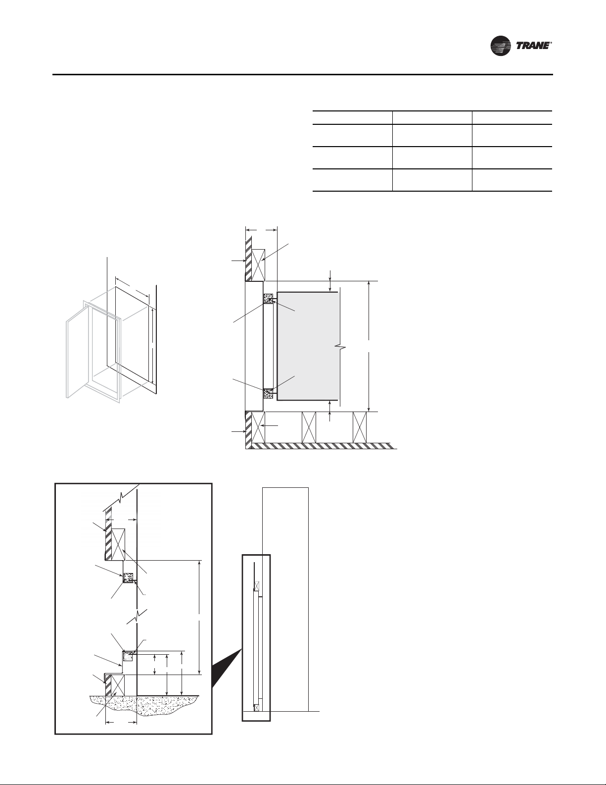
Dimensions and Weights
Return Air (hinged) Acoustical Door
The hinged acousticaldoor is recessedinto the wall so that
the door is flush with the surface of the wall.
The opening through the wall for the door assembly must
be centered with the return-air opening of the unit cabinet.
For full installing instructions of the return-air acoustical
door, see p. 14.
Figure 3. Return air (hinged) acoustical door
3 1/2” ±3/8”
SHEETROCK
A
RETURN AIR OPENING
FLANGE ON CABINET
B
RETURN AIR
DOOR FLANGE
RETURN AIR OPENING
FLANGE ON CABINET
Table 3. Return air hinged acoustical door
Unit Size A B
2“ X 4” STUD
1“ X 1” CLOSED
CELL INSULATION
CABINET
1“ X 1” CLOSED
CELL INSULATION
1 1/4”
+1/2”/-0”
009
012
015
018
024
036
A
19¼”
(489)
23¼”
(591)
27 1/8”
(689)
44 1/8”
(1121)
45¼”
(1149)
54 5/8”
(1387)
SHEETROCK
RETURN AIR
DOOR FRAME
1“ X 1” CLOSED
CELL INSULATION
1“ X 1” CLOSED
CELL INSULATION
RETURN AIR
DOOR FRAME
SHEETROCK
FLOOR
SHEET ROCK
OPENING
3 1/2” ±3/8”
K
2 X 4 STUD
RETURN-AIR OPENING
FLANGE ON CABINET
RETURN-AIR OPENING
FLANGE ON CABINET
2 1/4“
4 5/8“
CABINET
SHEETROCK
Note:
Finished wall and framing should not
touch the unit cabinetry.
B
5“
2“ X 4”
STUD
CABINET
1 1/4”
+1/2”/-0”
TOP VIEW
1 1/2” X 2 3/8”
3 1/2” ±3/8”
SIDE VIEW
WSHP-SVX10B-EN 11
Loading...