


 Loading...
Installation, Operation,
and Maintenance
Vertical Unit Ventilator
Classroom Unit Ventilator—Model VUV
Models |
“A” and later Design Sequence |
VUVE |
750 cfm—1500 cfm |
 SAFETY WARNING
Only qualified personnel should install and service the equipment. The installation, starting up, and servicing of heating, ventilating, and air-conditioning equipment can be hazardous and requires specific knowledge and training. Improperly installed, adjusted or altered equipment by an unqualified person could result in death or serious injury. When working on the equipment, observe all precautions in the literature and on the tags, stickers, and labels that are attached to the equipment.
January 2013 |
UV-SVN03F-EN |
Warnings, Cautions and Notices
Warnings, Cautions, and Notices. Note that warnings, cautions, and notices appear at appropriate intervals throughout this manual. Warnings are provide to alert installing contractors to potential hazards that could result in death or personal injury. Cautions are designed to alert personnel to hazardous situations that could result in personal injury, while notices indicate a situation that could result in equipment or property-damage-only accidents.
Your personal safety and the proper operation of this machine depend upon the strict observance of these precautions.
Read this manual thoroughly before operating or servicing this unit.
ATTENTION: Warnings, Cautions, and Notices appear at appropriate sections throughout this literature. Read these carefully:
 WARNING
 CAUTIONs
NOTICE:
Indicates a potentially hazardous situation which, if not avoided, could result in death or serious injury.
Indicates a potentially hazardous situation which, if not avoided, could result in minor or moderate injury. It could also be used to alert against unsafe practices.
Indicates a situation that could result in equipment or property-damage only
Important
Environmental Concerns!
Scientific research has shown that certain man-made chemicals can affect the earth’s naturally occurring stratospheric ozone layer when released to the atmosphere. In particular, several of the identified chemicals that may affect the ozone layer are refrigerants that contain Chlorine, Fluorine and Carbon (CFCs) and those containing Hydrogen, Chlorine, Fluorine and Carbon (HCFCs). Not all refrigerants containing these compounds have the same potential impact to the environment. Trane advocates the responsible handling of all refrigerants-including industry replacements for CFCs such as HCFCs and HFCs.
Responsible Refrigerant Practices!
Trane believes that responsible refrigerant practices are important to the environment, our customers, and the air conditioning industry. All technicians who handle refrigerants must be certified. The Federal Clean Air Act (Section 608) sets forth the requirements for handling, reclaiming, recovering and recycling of certain refrigerants and the equipment that is used in these service procedures. In addition, some states or municipalities may have additional requirements that
must also be adhered to for responsible management of refrigerants. Know the applicable laws and follow them.
 WARNING
Contains Refrigerant!
System contains oil and refrigerant under high pressure. Recover refrigerant to relieve pressure before opening the system. See unit nameplate for refrigerant type. Do not use non-approved refrigerants, refrigerant substitutes, or refrigerant additives.
Failure to follow proper procedures or the use of nonapproved refrigerants, refrigerant substitutes, or refrigerant additives could result in death or serious injury or equipment damage.
 WARNING
Proper Field Wiring and Grounding
Required!
All field wiring MUST be performed by qualified personnel. Improperly installed and grounded field wiring poses FIRE and ELECTROCUTION hazards. To avoid these hazards, you MUST follow requirements for field wiring installation and grounding as described in NEC and your local/state electrical codes. Failure to follow code could result in death or serious injury.
 WARNING
Personal Protective Equipment (PPE)
Required!
Installing/servicing this unit could result in exposure to electrical, mechanical and chemical hazards.
•Before installing/servicing this unit, technicians MUST put on all PPE required for the work being undertaken. ALWAYS refer to appropriate MSDS sheets and OSHA guidelines for proper PPE.
•When working with or around hazardous chemicals, ALWAYS refer to the appropriate MSDS sheets and OSHA guidelines for information on allowable personal exposure levels, proper respiratory protection and handling instructions.
•If there is a risk of arc or flash, technicians MUST put on all PPE in accordance with NFPA 70E or other country-specific requirements for arc flash protection, PRIOR to servicing the unit.
Failure to follow instructions could result in death or serious injury.
© 2013 Trane All rights reserved |
UV-SVN03F-EN |

Warnings, Cautions and Notices
 WARNING
Hazard of Explosion and Deadly Gases!
Never solder, braze or weld on refrigerant lines or any unit components that are above atmospheric pressure or where refrigerant may be present. Always remove refrigerant by following the guidelines established by the EPA Federal Clean Air Act or other state or local codes as appropriate. After refrigerant removal, use dry nitrogen to bring system back to atmospheric pressure before opening system for repairs. Mixtures of refrigerants and air under pressure may become combustible in the presence of an ignition source leading to an explosion. Excessive heat from soldering, brazing or welding with refrigerant vapors present can form highly toxic gases and extremely corrosive acids. Failure to follow all proper safe refrigerant handling practices could result in death or serious injury.
Introduction
Important: Equipment is shipped FOB (Free On Board) at the manufacturer. Therefore, freight claims for damages against the carrier must be initiated by the receiver.
Trademarks
ComfortLink, EarthWise, Rover, Tracer, Tracer Summit, Trane, and the Trane logo are trademarks or registered trademarks of Trane in the United States and other countries. All trademarks referenced in this document are the trademarks of their respective owners.
BACnet is a registered trademark of American Society of Heating, Refrigerating and Air-Conditioning Engineers (ASHRAE); Echelon, LonTalk, and LONWORKS are registered trademarks of Echelon Corporation; Energizer is a registered trademark of Eveready Battery Company, Inc.; National Electrical Code, National Fire Protection Association, and NEC are registered trademarks of the National Fire Protection Association.
UV-SVN03F-EN |
3 |

Table of Contents
Introduction . . . . . . . . . . . . . . . . . . . . . . . . . . . 3
. . . . . . . . . . . . . . 6
General Information . . . . . . . . . . . . . . . . . . . . . 8
Unit Description . . . . . . . . . . . . . . . . . . . . . 8
Options . . . . . . . . . . . . . . . . . . . . . . . . . . . . 8
. . . . . . . . . . . . . . . . . . 10
Dimensions and Weights . . . . . . . . . . . . . . . . 11
Unit Location and Clearances . . . . . . . . . 11
. . . . . . . . . . . . . . . . . 18
Pre-Installation . . . . . . . . . . . . . . . . . . . . . . . . . 19
Jobsite Inspection . . . . . . . . . . . . . . . . . . 19
Jobsite Storage . . . . . . . . . . . . . . . . . . . . 19
Installation—Mechanical . . . . . . . . . . . . . . . . 20
Wall Box Installation . . . . . . . . . . . . . . . . 20
General Installation Checks . . . . . . . . . . . 20
Location Considerations . . . . . . . . . . . . . 21
Unit Mounting . . . . . . . . . . . . . . . . . . . . . 21
Installation—Piping . . . . . . . . . . . . . . . . . . . . . 24
Piping Installation . . . . . . . . . . . . . . . . . . . 24
Refrigerant Piping . . . . . . . . . . . . . . . . . . 25
Steam Piping . . . . . . . . . . . . . . . . . . . . . . 25
Modulating Water Valves (Option) . . . . . 25
Heating Coils with Direct Expansion Cooling
. . . . . . . . . . . . . . . . . . . . . . . . . . . . . . . . . . 28
Installation—Sensors . . . . . . . . . . . . . . . . . . . 29
Control Options . . . . . . . . . . . . . . . . . . . . . . 29
Installing Wall-Mounted Wired Sensors . 30
Location Considerations . . . . . . . . . . . . . 31
Location Considerations for Wireless zone sensors . . . . . . . . . . . . . . . . . . . . . . . . . . . 31
Fan Mode Switch Installation . . . . . . . . . 31 Zone Sensor Installation . . . . . . . . . . . . . 31
Wireless Sensors . . . . . . . . . . . . . . . . . . . . . 32
Address Setting . . . . . . . . . . . . . . . . . . . . 32
Observing the Receiver for Readiness to Associate . . . . . . . . . . . . . . . . . . . . . . . . . . . . 33
Associating the Sensor to the Receiver . 33
Testing Signal Strength and Battery Status
. . . . . . . . . . . . . . . . . . . . . . . . . . . . . . . . . . 34
Configuring the Wireless Display Sensor (Model WDS only) . . . . . . . . . . . . . . . . . . .35
Sensor Operations . . . . . . . . . . . . . . . . . . .37
Wireless Sensor Specifications . . . . . . . . .40
Installation—Electrical . . . . . . . . . . . . . . . . . . .42
Wiring . . . . . . . . . . . . . . . . . . . . . . . . . . . . .42
Electrical Wiring . . . . . . . . . . . . . . . . . . . . .42
Electric Heat (Option) . . . . . . . . . . . . . . . . .43
DX System . . . . . . . . . . . . . . . . . . . . . . . . .43
Split System Start-Up . . . . . . . . . . . . . . . .43
ECM Overview and Setup . . . . . . . . . . . . . . . .45
Overview . . . . . . . . . . . . . . . . . . . . . . . . . . . . .45
General Information . . . . . . . . . . . . . . . . . . .45
Trane BLDC Motor . . . . . . . . . . . . . . . . . . .45
ECM Engine Controller . . . . . . . . . . . . . . .45
Standard Adapter Board . . . . . . . . . . . . . .46
CSTI Adapter Board . . . . . . . . . . . . . . . . . .46
Installation and Initial Setup . . . . . . . . . . . .47
Installation and Initial Setup . . . . . . . . . . .47
Adjustment and Configuration of the Engine
Board . . . . . . . . . . . . . . . . . . . . . . . . . . . . . .49
Status Display . . . . . . . . . . . . . . . . . . . . . . .50
Initial Setup and Configuration . . . . . . . . .55
Configuration . . . . . . . . . . . . . . . . . . . . . . . . .55
Configuring the ECM Engine Controller . .55
Configuring the ECM Engine Board . . . . .60
Time Clock . . . . . . . . . . . . . . . . . . . . . . . . . . . . . .65
Setting the Time Clock . . . . . . . . . . . . . . . .65
Wired Controllers—Communication Wiring 67
Wiring Installation (ZN520) . . . . . . . . . . . . .67
Device Addressing . . . . . . . . . . . . . . . . . . .67
Recommended Communication Wiring Practices . . . . . . . . . . . . . . . . . . . . . . . . . . . . . . .67
Wiring Installation (Tracer UC400) . . . . . . .67
Wiring Overview Outline . . . . . . . . . . . . . .68
General Instructions . . . . . . . . . . . . . . . . . .68
BACnet MS/TP Link . . . . . . . . . . . . . . . . . .68
Power Supply . . . . . . . . . . . . . . . . . . . . . . .69
Pre-Start . . . . . . . . . . . . . . . . . . . . . . . . . . . . . . . .71
4 |
UV-SVN03F-EN |

Pre-Start-up Checklist . . . . . . . . . . . . . . . |
71 |
Startup . . . . . . . . . . . . . . . . . . . . . . . . . . . |
. . |
. . . |
72 |
Tracer ZN520 Unit Startup . . . . . . . |
. . |
. . . |
72 |
Tracer UC400 Unit Startup . . . . . . |
. . |
. . . |
72 |
General Information . . . . . . . . . . . . . |
. |
. . . |
72 |
Fan Mode Switch Operation . . . . . . |
. |
. . . |
72 |
Tracer ZN520 Operation . . . . . . . . . |
. |
. . . |
72 |
UC400 Controller Operation . . . . . . |
. |
. . . |
73 |
Tracer ZN520 Sequence of Operation |
. . . |
73 |
|
Cooling Operation (Tracer ZN520) . . . . . |
74 |
||
Fan Mode Operation (Tracer ZN520) |
. . . 75 |
||
UC400 Sequence of Operation . . . . . |
. |
. . . |
80 |
Power-up Sequence (UC400) . . . . . |
. |
. . . |
80 |
Random Start (UC400) . . . . . . . . . . . |
. |
. . . |
80 |
Occupancy Modes (UC400) . . . . . . . |
. |
. . . |
80 |
Timed Override Control (UC400) . . |
. |
. . . |
81 |
Zone Temperature Control (UC400) . . . . 81 |
|||
Discharge Air Tempering (UC400) |
. . . . . 82 |
||
Heating or Cooling Mode (UC400) |
. . . . . 82 |
||
Entering Water Temperature Sampling Func- |
|||
tion (UC400) . . . . . . . . . . . . . . . . . . . |
. |
. . . |
82 |
Fan Operation (UC400) . . . . . . . . . . |
. |
. . . |
82 |
Exhaust Control (UC400) . . . . . . . . . |
. |
. . . |
83 |
Valve Operation (UC400) . . . . . . . . . |
. |
. . . |
83 |
Modulating Outdoor/Return Air Damper |
|
||
(UC400) . . . . . . . . . . . . . . . . . . . . . . . |
. |
. . . |
84 |
Two-position Control Of A Modulating Out- |
|||
door Air Damper (UC400) . . . . . . . . |
. |
. . . |
85 |
Electric Heat Operation (UC400) . . . |
. |
. . . |
85 |
Dehumidification Operation (UC400) |
. . . 85 |
||
Peer-to-peer Communication (UC400) . . 85 |
|||
Unit Protection Strategies (UC400) . |
. |
. . . |
85 |
Maintenance . . . . . . . . . . . . . . . . . . . . . . . |
. |
. . . |
87 |
Service Access . . . . . . . . . . . . . . . . . |
. |
. . . |
87 |
Periodic Maintenance . . . . . . . . . . . |
. |
. . . |
87 |
Preventive Maintenance . . . . . . . . . |
. |
. . . |
89 |
Diagnostics . . . . . . . . . . . . . . . . . . . . . . . . |
. |
. . . |
90 |
Troubleshooting Checklist . . . . . . . . |
. |
. . . |
90 |
Output Testing and Diagnostics (Tracer |
|
||
ZN520) . . . . . . . . . . . . . . . . . . . . . . . . . . |
. |
. . . |
91 |
Output Testing and Diagnostics (UC400) . 95
Output Testing (UC400) . . . . . . . . . . . . . . .95
Diagnostics (UC400) . . . . . . . . . . . . . . . . .95
Troubleshooting (Wireless Controls) . . . . .96
Troubleshooting (Tracer ZN520) . . . . . . .102
Troubleshooting (UC400) . . . . . . . . . . . .103
Troubleshooting (ECM) . . . . . . . . . . . . . .105
General Information (ECM) . . . . . . . . . . .106
Troubleshooting Information (ECM) . . .106
Replacing ECM Components . . . . . . . . . . . .108
Circuit Modules Replacement Notes/Work Instructions . . . . . . . . . . . . . . . . . . . . . . . . .109
Softsetting the IMC Address of an ECM Engine Module . . . . . . . . . . . . . . . . . . . . . . .110
UV-SVN03F-EN |
5 |

Model Number Descriptions
Vertical Unit
Ventilator Model
Number
Digits 1, 2, 3 — Unit
Configuration
VUV= Vertical Unit Ventilator
Digit 4 — Development
Sequence
E
Digits 5, 6, 7 — Nominal Airflow
075 = |
750 cfm |
100 = |
1000 cfm |
125 = |
1250 cfm |
150 = |
1500 cfm |
Digit 8 — Voltage (Volts/Hz/
Phase)
0 |
= |
115/60/1 |
1 |
= |
208/60/1 |
2 |
= |
230/60/1 |
3 |
= |
208/60/3 |
4 |
= |
460/60/3 |
7 |
= |
277/60/1 |
8 |
= |
230/60/3 |
Digit 9 — Open Digit = 0
Digits 10, 11 — Current Design
Sequence
Digit 12 — Face & Bypass
Y |
= |
Yes, Include Damper |
N |
= |
No Damper |
Digit 13 — Unit Arrangement
1= Return Air Front / Fresh Air Back
2= 100% Return Air Front
3= 100% Fresh Air Back
4= Dynamic Air Barrier
5= ERS-Compatible w/RH Connection
6= ERS-Compatible w/LH Connection
Digit 14 — Preheat / Reheat /
Changeover
A= 4-Pipe Preheat (RH Clg/LH Htg)
B= 4-Pipe Preheat (LH Clg/RH Htg)
C= 4-Pipe Reheat (RH Clg/LH Htg)
D= 4-Pipe Reheat (LH Clg/RH Htg)
E= 2-Pipe (RH Connections)
F= 2-Pipe (LH Connections)
Digit 15 — Cooling / 2-Pipe Coil
0 = None
B= 2-Row, 12 F.P.I.
C= 2-Row, 16 F.P.I.
D= 3-Row, 12 F.P.I.
E= 3-Row, 16 F.P.I.
F= 4-Row, 12 F.P.I.
G= 4-Row, 14 F.P.I.
H= 3-Row, 16 F.P.I, EarthWise™ Coil
J = 3-Row, DX (R-410A) Cooling Coil
Digit 16 — Heating Coil
0 = None
A= 1-Row, 12 F.P.I.
B= 2-Row, 12 F.P.I.
C= 2-Row, 16 F.P.I.
D= 3-Row, 12 F.P.I.
E= 3-Row, 16 F.P.I.
F= 4-Row, 12 F.P.I.
G= 4-Row, 14 F.P.I.
H= 3-Row, 16 F.P.I, EarthWise Coil
K= Steam Low
L= Steam High
M= Electric Heat - Low
N= Electric Heat - Med
P= Electric Heat - High
Digit 17 — Motor
0 = ECM
1= ECM & Low Acoustic Option
2= ECM & Low FLA Option
3= ECM & Low Acoustic & Low FLA Option
Digit 18 — Other Motor Items
A |
= |
None |
B |
= |
Toggle |
C |
= |
Circuit Breaker |
Digit 19 — 2- or 3-Way Valve - Cooling Changeover Coil
0 = None
2= 2-Way; 3-Point Floating
3= 3-Way; 3-Point Floating
4= 2-Way; 2–10 Volt
5= 3-Way; 2–10 Volt
6= Isolation Valve; 2-Way
7= Isolation Valve; 3-Way
Digit 20 — CV - Cooling or Changeover Coil
0 = None
L= Low Cv
M= Medium Cv
H= High Cv
Digit 21 — 2- or 3-Way Valve - Preheat or Reheat Heating Coil
0 = None
2= 2-Way; 3-Point Floating
3= 3-Way; 3-Point Floating
4= 2-Way; 2–10 Volt
5= 3-Way; 2–10 Volt
6= Isolation Valve; 2-Way
7= Isolation Valve; 3-Way
Digit 22 — CV - Preheat or Reheat Heating Coil
0 = None
L= Low Cv
M= Medium Cv
H= High Cv
Digit 23 — Discharge
Arrangement
0 = Opening Only, No Grille
A= Discharge Grille
B= Double Deflection Discharge Grille
C= Grille Discharge with Wire Mesh
Digit 24 — Outside Air Damper
Control
0 = None
A= 3-Wire Actuator
B= 2–10 Volt Actuator
Digit 25 — Face and Bypass
Damper Control
0 = None
A= 3-Wire Actuator
B= 2–10 Volt Actuator
Digit 26 — Controls
0 = None, Unit-Mounted Speed
Switch
2= Customer Supplied Terminal Interface (CSTI)
3= CSTI w/Low Temp Detection
4= Tracer™ ZN520
5= Tracer ZN520 w/Time Clock
6= Tracer ZN520 w/Fan Status
7= Tracer UC400
8= Tracer UC400 w/Time Clock
Digit 27 — Unitor WallMounted Controls
0 |
= |
None |
1 |
= |
Unit-Mounted |
2 |
= |
Wall-Mounted |
3= Unit-Nounted Fan Speed Switch & Wall-Mounted Temperature Sensor
4= Wireless Zone Sensor
Note: The wall-mounted room sensor is ordered as separate line item in Job Configurator.
Digit 28 — Internal or External Set Point
0 |
= |
None |
1 |
= |
Internal |
2 |
= |
External |
3 |
= |
Digital Display |
Digit 29 — Timed Override
0 |
= |
No |
1 |
= |
Yes |
Digit 30 — Exhaust Control
A= No Exhaust Control with 3-Speed Supply Fan
B= Exhaust Control with 2-Speed Supply Fan
C= No Exhaust Control with 1-Speed Supply Fan (DX/EH Units)
D= Exhaust Control with 1-Speed Supply Fan (DX/EH Units)
Digit 31 — DDC Programming
0 = None
1= Humidity Sensor Programming
2= CO2 Sensor Programming
Note: The humidity and CO2 sensor must be ordered as a separate line item in Job Configurator.
6 |
UV-SVN03F-EN |

Model Number Descriptions
Digit 32 — Unit Depth
A= Standard (16-5/8 in.)
B= 21-1/4 in. Depth with Baffle
C= 21-1/4 in. Depth with Full Sheet Metal Back and Baffle
D= 21-1/4 in. Depth with 25 in. High Falseback
E= 21-1/4 in. Depth with 26 in. High Falseback
F= 21-1/4 in. Depth with 27 in. High Falseback
G= 21-1/4 in. Depth with 28 in. High Falseback
H= 21-1/4 in. Depth with 29 in. High Falseback
J = 21-1/4 in. Depth without Baffle
Note: Selection “J” should be applied if OA opening is raised above standard baffle location.
Digit 33 — End Covers
0 = None
1= 16-5/8 in. Depth without Cutouts
2= 16-5/8 in. Depth with 3 x 7-1/4 in. Cutout
4= 21-1/4 in. Depth without Cutouts
5= 21-1/4 in. Depth with 3 x 7-1/4 in. Cutout
6= 21-1/4 in. Depth with 3-1/4 in. x 16-7/8 in. Cutout
Digit 34 — Front Panel
1= Standard Front Panel
2= Heavy Gauge Front Panel
Digit 35 — Subbase
0 |
= |
No Subbase |
2 |
= |
2 in. Subbase |
4 |
= |
4 in. Subbase |
6 |
= |
6 in. Subbase |
Digit 36 — Piping Package
0 = None
1= Ball Valves & P/T Ports
2= Ball Valve & Circuit-Setter with P/T Ports
3= Ball Valve, Circuit-Setter with P/T Ports & Strainer
Digit 37 — Flow Control -
Cooling/Changeover Coil
0 = None
Digit 38 — Flow Controls -
Heating Coil
0 = None
Digit 39 — Auxiliary Drain Pan -
Piping
Y = Yes, Auxiliary Drain Pan
N = No Auxiliary Drain Pan
Digit 40 — Crossover Piping
0 |
= |
None |
1 |
= |
Internal |
2= External 1-3/8 in. Crossover Piping
3= External 2-1/8 in. Crossover Piping
Digit 41 — Filter
1= Standard Throwaway Filter
2= MERV 8 Filter
3= MERV 13 Filter
Digit 42 — Color
1= Deluxe Beige
2= Cameo White
3= Soft Dove
4= Stone Gray
5= Driftwood Gray
UV-SVN03F-EN |
7 |

General Information
Unit Description
Unit Nameplate. The unit nameplate is located in the left hand end pocket, behind the control box. It includes the unit model number, serial number, electrical characteristics, and other pertinent unit data.
Factory Shipment. Before shipment, each unit is leaktested and run-tested for proper control operation.
Access. A three-panel front access of the unit ventilator allows for speedy set-up during field commissioning. This design allows for the end pocket of the unit ventilator to be open while the fan (airside) section stays closed.
End Pockets. Access for piping and controls is made through the unit ventilator’s end pockets.
Coil Connections. The coil headers and drain connections are made within the unit chassis to allow a tight seal and help prevent air leakage around the coil. The connection sizes vary dependent upon type of coil combination specified.
Coil type |
Size (in.) |
|
|
Hydronic cooling (main) coil or |
3/4 in. nominal |
Heating/cooling changeover coil |
7/8 in. ID |
|
|
Heating (auxiliary) coil |
1/2 in. nominal |
|
5/8 in. ID |
|
|
Steam heating coil |
1 in. FNPT |
|
|
Direct expansion coil |
3/8 in. OD liquid |
|
7/8 in. OD suction |
|
|
Unit Drain Pan. The drain pan is dual-sloped for effective condensate removal. It is made from a noncorrosive material to help eliminate issues associated to leaking or standing water. It may be easily removed for cleaning. The drain pan connection size for all Trane VUVE models is 7/8 in. OD.
Motor. Motors for the VUVE model do not include an external fan bearing on the end of the fan shaft. This helps avoid issues related to fan bearing maintenance (oiling is not needed), and/or bearing replacement.
Filters. Filter sizing for the unit ventilator are an off-the- shelf design to reduce or help eliminate local stocking of the filters. Options include throwaway filters, MERV 8, and MERV 13 filters.
Sliding Fan Deck. Convenient access to the fan motor and wheels for maintenance and serviceability may be made through Trane’s easy-slide fan deck design.
Note: Ground wire must be reconnected if removed for service of fan deck.
Outside-Air/Return-Air Dampers. The outside-air/ return-air damper is a one piece, linkage free design resulting in a superior air-tight seal.
Options
Field-Installed Controls (Option). The unit comes equipped with a fan speed switch, damper blade (only), and an optional low temperature detection.
Customer Supplied Terminal Interface (CSTI)
(Option). Units containing the end device control design will incorporate a pre-wired, selected control components to a terminal strip for wiring a field-provided controller and temperature sensor.
Note: For controller operation malfunction of any nonTrane, field installed controls, consult the literature or technical support of the controls manufacturer.
Tracer ZN520 Control Package (Option). The Tracer ZN520 electronic digital controller is a factory installed, tested and commissioned LonTalk® certified design. It may be used in a stand-alone control scheme, or as part of a building automation system. The controller is pre-wired to Trane selected control components best suited for room comfort. For more information on the Tracer ZN520 unit controller operation and service issues, refer to CNT-SVX04A-EN (Installation, Operation, and Programming Guide: Tracer ZN520 Unit Controller), or the most recent version.
Tracer UC400 Control Package (Option). The Tracer UC400 electronic digital controller is a factory installed, tested and commissioned BACnet® certified design. The Tracer UC400 operates as a single zone VAV controller and ramps fan speed based on space load. It may be used in a stand-alone control scheme, or as part of a building automation system. The controller is mounted, pre-wired, and pre-programmed to selected control components best suited for room comfort. For more information on the Tracer UC400 unit controller operation and service issues, refer to BAS-SVX48B-EN (Installation, Operation, and Programming Manual: Tracer UC400 Programmable Controller), or the most recent version.
OA/RA Actuator (Option). The OA/RA actuator provides true spring-return operation for positive close-off of the OA/RA damper. The spring return system of the actuator closes the outside damper if power is lost to the building. When ordered with factory controls, the actuator is a 3-point floating design. A 2 to 10 Vdc actuator is available when other than Trane controls are specified. Refer to Table 1, p. 9 for OA/RA technical data.
Note: Because the damper actuator is a spring return type an inner spring will close the damper upon loss of power. If the need to service or replace the actuator is required, the spring must be “loaded” for the damper to function properly. The term loaded means that the blade must be held in the return air position upon replacement of the actuator.
8 |
UV-SVN03F-EN |

General Information
Face and Bypass Actuator (Option). The face and bypass damper actuator incorporates a direct couple design. It provides electronic protection against overload. A limit switch is not included, nor required as part of the design. When reaching the damper end position, the actuator automatically stops. The gears can be manually disengaged with a button on the housing. Refer to Table 2, p. 9 for face and bypass actuator specifications.
Modulating Water Valves (Option). The modulating control valve provides optimum control of hot and chilled water flow in various heating and cooling applications.
They are designed to provide sinusoidal valve actuator travel and operate silently, resisting water hammer.
The actuator on the valve is a 24V, 3-point floating type. Refer to Table 3 for modulating water valve specifications.
Isolation Valve (Option). The isolation valve is a two position 24V, spring return type valve. It provides added control in heating and cooling applications when used in conjunction with the face and bypass damper.
On heating coils, and two-pipe changeover applications, the valve is normally open to help prevent the coil from freezing in-case of power loss.
For cooling, the valve is normally closed and opens when there is a call for cooling. Refer to Table 4, p. 9 for isolation valve specifications.
Table 1. |
OA/RA actuator specification |
||
|
|
|
|
|
|
|
|
|
Power supply |
24 Vac ±20% 50/60 Hz |
|
|
|
|
24 Vac ±10% |
|
|
|
|
|
Power consumption |
Running: 2.5 W |
|
|
|
|
Holding: 1 W |
|
|
|
|
|
Transformer sizing |
5 VA (class 2-power source) |
|
|
|
|
|
|
Overload protection |
Electronic throughout 0° to 95° rotation |
|
|
|
|
|
|
Control signal |
2 to 10 Vdc |
|
|
|
|
3-point floating with Trane controls |
|
|
|
|
|
Angle of rotation |
Maximum 95° |
|
|
|
|
Adjustable with mechanical stop |
|
|
|
|
|
Torque |
|
35 in·lb |
|
|
|
|
|
Direction of rotation |
Spring return reversible with cw/ccw |
|
|
|
|
mounting |
|
|
|
|
|
Position indication |
Visual indicator, 0° to 95° |
|
|
|
|
|
|
Noise level |
|
Running: 30 dB |
|
|
|
|
Table 2. Face-bypass actuator specification
|
|
|
|
|
Power supply |
24 Vac ± 20% 50/60 Hz |
|
|
|
24 Vac ± 10% |
|
|
Power consumption |
2 W |
|
|
|
|
|
|
Transformer sizing |
3 VA (class 2-power source) |
|
|
|
|
|
|
Angle of rotation |
Maximum 95-degree |
|
|
|
Adjustable with mechanical stop |
|
|
|
|
|
|
Torque |
35 in./lb |
|
|
|
|
|
|
Direction of rotation |
Reversible with switch L/R |
|
|
|
|
|
|
Position indication |
Clip-on indicator |
|
|
|
|
|
|
Manual override |
External push button |
|
|
|
|
|
|
Noise level |
Less than 35 dB |
|
|
|
|
|
|
Control signal |
3-point floating |
|
|
|
|
|
Table 3. Mod. water valve specification |
|||
|
|
|
|
|
|
|
|
|
Power supply |
|
24 Vac - 50/60 Hz |
|
Power consumption |
|
4 W |
|
|
|
|
|
Max. duty cycle |
|
15% |
|
|
|
|
|
Operating ambient temp. |
0 to 65°C |
|
|
|
|
32 to 150°F |
|
|
|
|
|
Min./max. fluid temp. |
|
1 to 95°C |
|
|
|
34 to 203°F |
|
|
|
|
|
Operating pressure |
|
Max. - 4 bar (60 psi) |
|
differential |
|
|
|
|
|
|
|
Pressure rating |
|
Static - 20 bar (300 psi) |
|
|
|
Burst - 100 bar (1500 psi) |
|
|
|
|
|
Flow characteristic |
|
Linear |
|
|
|
|
Table 4. Isolation valve specification
|
|
Power supply |
24 Vac - 50/60 Hz |
Power consumption |
5 W |
|
|
Max. fluid temp. |
94°C |
|
200°F |
|
|
Min. fluid temp. |
1°C |
|
34°F |
|
|
Max. operating pressure |
300 psi |
|
|
Max. close-off pressure |
1/2 in. = 30 psi |
|
3/4 in. = 20 psi |
|
1 in. = 15 psi |
|
|
UV-SVN03F-EN |
9 |

ECM Application Notes
The new Trane BLDC system has some notable differences to traditional designs.
RPM Mode
The motors are programmed from the factory to run in rpm mode and will not change rpm based on external static pressure, except at the performance limits of the motor/controller. For ducted units, the units are shipped with the rpm set for 0.2 in. ESP for High, Medium, and Low speeds. The speeds can for high, medium, and low operation, but should not be changed for the electric heat actuation speeds.
Generally, the fans deliver less cfm for the same rpm, if the static is increased and the power will decrease. The fan will deliver more cfm for the same rpm, if the static is decreased and the fan power will increase. A unit with high static configuration should not be used to free-deliver air (i.e., with no ducting attached).
Field Power Wiring
Note: This product uses an electronic variable speed motor control, which includes a line reactor to minimize power line harmonic currents. It is recommended that good wiring practices be followed to manage building electrical power system harmonic voltages and currents to avoid electrical system problems or other equipment interaction.
Performance Boundaries
While the speeds of the fan motors can be adjusted, never program a fan speed higher than 1700 rpm, or lower than 450 rpm. In many cases, units configured for high-static operation will not achieve the desired rpm if the ESP of the unit is too low, or the unit is allowed to “free-discharge.” The ECM engine contains settings that will limit the output power of the motor under these overload conditions. If the motors cannot achieve rpm close to the target for a specific period of time, the unit will disable electric heat and fanstatus indicators.
MCA/MFS and Power Draw
The Trane BLDC motors have variable output but are shipped at specific settings to deliver proper performance and reliability. The power draw indicated in the catalogue indicates the power consumed when applied properly (as shipped and with the nominal ESP applied). However, the nameplate of the unit indicates the maximum input draw of the motor, as the motor settings can be changed to draw more power.
Electric Heat Relays
For quiet operation, the new BLDC units employ power relays instead of definite purpose contactors for electric heat actuation. The coils of multiple relays are hooked in parallel to simulate a multi-pole contactor, as shown in Figure 1. In Figure 1, two sets of three relays are used to
perform the function of a two 3-pole contactors.
Figure 1. Sample arrangement: electric heat relay
Troubleshooting Other Unit Functions
In some cases, the normal or abnormal operation of the BLDC system may interact with other components in the system. Generally, verification of the engine and adapter boards’ wiring and configuration should be checked if there are unexplained abnormalities in other areas of the unit:
1.Valve operation
2.Electric Heat operation
3.Changeover sensor operation
4.Damper operation
5.Condensate overflow switch
A high degree of protection is provided on electric heat units. If electric heat fails to actuate, it may be because of one of the following events:
1.Fans are failing to meet target speed. If a second motor is not present, all settings for speeds for Motor 2 should be set to 0000.
2.Hot water may be available in the changeover coil.
3.The connection to analogue input 1 on the Tracer ZN controller may be reversed in polarity.
4.Target speeds for motors may be set too high:
a.The parameter may be set incorrectly.
b.The parameter may be set incorrectly.
10 |
UV-SVN03F-EN |
Dimensions and Weights
Unit Location and Clearances
Locate the unit in an indoor area. The ambient temperature surrounding the unit must not be less than 45°F. Do not locate the unit in areas subject to freezing.
NOTICE:
Equipment Damage!
Do not locate the unit in areas subject to freezing. Pipes could burst at lower temperature resulting in equipment damage.
Attention should be given to service clearance and technician safety. The unit should contain enough space for service personnel to perform maintenance or repair. Provide sufficient room to make water, and electrical connection(s).
Table 5. VUVE general data
 WARNING
Electrocution and Fire Hazards with Improperly Installed and Grounded Field Wiring!
Improperly installed and grounded field wiring poses FIRE & ELECTROCUTION hazards. To avoid these hazards, you MUST follow requirements for field wiring installation and grounding as described in NEC and your local/state electrical codes. All field wiring MUST be performed by qualified personnel.
Failure to follow these requirements could result in death or serious injury.
A 36-inch clearance at the unit front is sufficient for maintenance and service of the equipment.
|
|
|
|
Unit size |
|
|
|
|
|
|
|
|
|
Description |
|
0750 |
1000 |
|
1250 |
1500 |
|
|
|
|
|
|
|
Unit length w/o end covers (in.) |
|
69 |
81 |
|
93 |
105 |
|
|
|
|
|
|
|
Unit depth - standard (in.) |
|
16-5/8 |
16-5/8 |
|
16-5/8 |
16-5/8 |
Unit depth - with false back (in.) |
|
21-1/4 |
21-1/4 |
|
21-1/4 |
21-1/4 |
|
|
|
|
|
|
|
Unit height - standard (in.) |
|
30 |
30 |
|
30 |
30 |
|
|
|
|
|
|
|
Shipping weight (lb) |
|
320 |
405 |
|
450 |
470 |
|
|
|
|
|
|
|
Nominal filter size (in.) and quantity |
|
14 x 20 x 1 (2) |
14 x 24 x 1 (1) |
|
14 x 20 x 1 (2) |
14 x 24 x 1 (2) |
|
|
|
14 x 30 x 1 (1) |
|
14 x 24 x 1 (1) |
14 x 30 x 1 (1) |
|
|
|
|
|
|
|
Dynamic air filter nominal size (in.) and quantity |
|
7 x 42 x 1 (1) |
7 x 54 x 1 (1) |
|
7 x 66 x 1 (1) |
7 x 78 x 1 (1) |
|
|
|
|
|
|
|
Drain connection size (in.) |
|
7/8 I.D. hose |
7/8 I.D. hose |
|
7/8 I.D. hose |
7/8 I.D. hose |
|
|
|
|
|
|
|
Fan type / quantity |
|
FC / 2 |
FC / 2 |
|
FC / 4 |
FC / 4 |
|
|
|
|
|
|
|
Motor data |
|
|
|
|
|
|
Quantity |
1 |
1 |
|
2 |
2 |
|
Horsepower (each) |
1/4 |
1/4 |
|
1/4 |
1/4 |
|
|
|
|
|
|
|
|
Coil volume (gal) |
|
|
|
|
|
|
Coil type A |
0.178 |
0.228 |
|
0.277 |
0.327 |
|
|
B |
0.311 |
0.410 |
|
0.510 |
0.610 |
|
C |
0.311 |
0.410 |
|
0.510 |
0.610 |
|
D |
0.444 |
0.571 |
|
0.704 |
0.931 |
|
E |
0.444 |
0.571 |
|
0.704 |
0.931 |
|
F |
0.610 |
0.809 |
|
1.014 |
1.213 |
|
G |
0.610 |
0.809 |
|
1.014 |
1.213 |
|
H |
0.395 |
0.593 |
|
0.742 |
0.837 |
|
|
|
|
|
|
|
Table 6. |
Control Methodology |
|
|
|
Fan Speed |
|
|
FSS |
3 or infinite(a) |
CSTI |
3 or infinite(a) |
ZN520 |
3 |
|
|
UC400 |
Infinite |
(a) With a field-supplied 2–10 Vdc controller.
Table 7. Control Sequences
|
Fan Speeds |
|
|
DX operation(a) |
1 |
Electric heat operation(a) |
1 |
Sidewall Exhaust(b) |
2 |
ERSA(b) |
2 |
(a)Fan speed during sequence operation.
(b)Unit Ventilator when operating with option.
UV-SVN03F-EN |
11 |

Dimensions and Weights
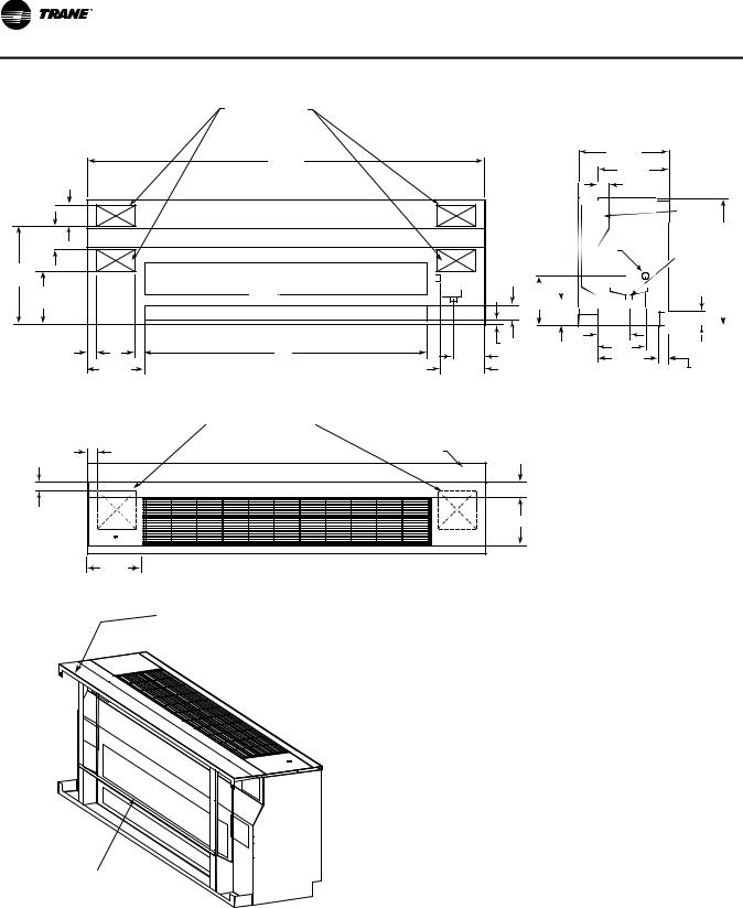
Figure 2. Standard depth unit
(4)K.O. FOR PIPING OR ELECTRICAL
|
|
A |
|
5 3/4" |
|
|
|
5" |
|
|
|
22 5/8" |
|
|
|
12 1/2" |
|
|
|
|
|
FRESH AIR OPENING (OPTIONAL) |
3 3/4" |
2 1/4" |
9" |
B |
3/4" |
8 1/8" |
|||
|
13 1/2" |
|
12 1/4" |
|
|
|
16 5/8" |
|
|
2 3/8" |
|
|
|
PIPE |
|
|
CHASE |
|
7/8" O.D. |
|
30" |
DRAIN CONN. |
7/8" O.D. |
|
|
|
|
|
AUX. |
|
|
DRAIN CONN. |
|
|
(optional) |
|
9 1/4" |
|
|
5 1/4" |
|
|
|
|
|
|
|
|
|
|
|
|
|
|
|
|
|
|
|
||
|
|
|
|
|
|
|
|
|
|
|
|
|
2 1/2" |
||||||||
|
|
|
|
|
|
|
|
|
|
|
|
|
|
|
|||||||
|
|
|
|
7" |
|
|
|
|
|
|
|
|
|
|
|
|
|
|
|||
|
|
|
|
|
|
|
|
|
|
|
|
|
|
|
|
|
|
||||
|
|
|
|
|
|
|
|
|
|
|
|
|
|
|
|||||||
|
|
|
|
|
|
11" |
|
|
|
|
|
|
|
|
|
|
|
|
|
|
|
|
|
|
|
|
|
|
|
|
|
|
|
|
|
|
|
|
|
|
|||
|
|
|
|
|
|
|
14 3/8" |
|
|
|
|
|
|
|
2 1/4" |
||||||
|
|
|
|
|
|
|
|
|
|
|
|
|
|
|
|
|
|
||||
|
|
|
|
|
|
|
|
|
|
|
|
|
|
|
|
|
|||||
BACK VIEW |
SIDE VIEW |
|
|
(2)9" x 9"[229mm x 229mm] |
|
13" |
KNOCKOUTS IN BOTTOM |
|
|
|
2 1/4" |
|
|
2" |
|
|
|
|
3 3/4" |
16 5/8" |
|
10 7/8" |
|
|
TOP VIEW
|
GRILLE |
|
|
|
UNIT MOUNTED |
UNIT SIZE |
NO. FANS |
A |
B |
FAN SWITCH |
||||
(OPTIONAL) |
|
|
|
|
|
075 |
2 |
69" |
42" |
|
100 |
2 |
81" |
54" |
|
FRONT OF UNIT |
|
|
|
|
125 |
4 |
93" |
66" |
|
150 |
4 |
105" |
78" |
RETURN AIR
(OPTIONAL)
NOTE:
1. THE UNIT LENGTH DOES NOT INCLUDE 5/8" END PANELS.
2. THE POWER CONNECTION IS MADE IN THE LEFT HAND END POCKET FOR ALL OPTIONS BUT ELECTRIC HEAT.
3. THE POWER CONNECTION FOR ELECTRIC HEAT OPTION IS MADE IN THE RIGHT HAND END POCKET.
12 |
UV-SVN03F-EN |

Dimensions and Weights
Figure 3. Falseback unit
|
|
|
|
|
|
|
|
|
A |
|
|
|
|
|
|
|
|
|
|
21 1/4" |
|
|
|
|
|
||||
|
|
|
|
|
|
|
|
|
|
|
|
|
|
|
|
|
|
|
|
|
|
16 5/8" |
|
|
|
|
|||
|
|
|
|
|
|
|
|
|
|
|
|
|
|
|
|
|
|
|
|
|
|
|
|||||||
|
|
|
|
|
|
|
|
|
|
|
|
|
|
|
|
|
|
|
|
|
|
2 3/8" |
|
|
|
|
|||
|
|
|
|
|
|
|
|
|
|
|
|
|
|
|
|
|
|
|
|
|
|
|
|
|
|
|
|
|
|
5 3/4" |
|
|
|
|
|
(4)K.O. FOR PIPING |
|
|
7/8" O.D. |
|
|
|
|
|
|
|
|
|
|
|
|
||||||||
|
|
|
|
|
|
|
|
|
|
PIPE |
|||||||||||||||||||
|
|
|
|
|
|
|
|
OR ELECTRICAL |
|
|
|
|
|
|
|
|
|
|
|
|
|
||||||||
|
|
|
|
|
|
|
|
|
|
|
|
|
|
|
|
|
|
|
|
|
|||||||||
|
DRAIN CONN. |
CHASE |
|||
5" |
|
|
|
7/8" O.D. 30 |
|
|
|
|
AUX. |
||
|
|
|
|
||
22 5/8" |
|
|
|
DRAIN CONN. |
|
|
18" |
1/4"9 |
1/4"5 |
(optional) |
|
12 1/2" |
2 |
/2 |
|||
|
|
|
|
|
|
FRESH AIR OPENING (OPTIONAL) |
3 3/4" |
|
|
|
|
|
|
|
|
|
|
|
|
|
|
|
|
|
|
|
|
|
|
|
|
|
7" |
|
|
|
|
|
|
|
|
|
|
|||
2 1/4" |
|
|
|
|
9" |
|
|
|
|
B |
|
|
|
|
|
8 1/8" |
3/4" |
|
|
|
11" |
|
|
|
|
|
|
|
|
|
|
|||
|
|
|
|
|
|
|
|
|
|
|
|
|
|
|
|
|
|
|
|
|
|
|
|
|
||||||||||
|
|
|
|
|
|
|
|
|
|
|
|
|
|
|
|
|
14 3/8" |
|
|
|
|
|
|
|
||||||||||
|
|
|
|
|
|
|
|
|
|
|
|
|
|
|
|
|
|
|
|
|||||||||||||||
|
|
|
|
|
|
|
|
|
|
|
|
|
|
|
12 1/4" |
|
|
|
|
|
|
|
|
|
|
|
|
|
|
|
|
|
|
|
|
|
|
13 1/2" |
|
|
|
|
|
|
|
|
|
|
|
|
|
|
|
|
|
|
|
|
|
|
|
|
2 1/4" |
||||||
|
|
|
|
|
|
|
|
|
BACK VIEW |
|
|
|
|
|
|
|
|
|
SIDE VIEW |
|||||||||||||||
|
|
|
STEP-DOWN |
21 1/4" |
|
|
|
IS IN 1" |
|
|
|
|
INCREMENTS |
16 5/8" |
|
|
|
|
|
|
(2)9" x 9"[229mm x 229mm] |
|
|
2 3/8" |
|
|
|
|
|
13" |
KNOCKOUTS IN BOTTOM |
|
|
|
|
|
|
|
|
2 1/4" |
|
FALSEBACK |
|
|
|
|
3 3/4" |
|
30" |
|
|
|
C |
|
2" |
|
|
|
|
|
|
18" |
|
|
|
|
10 7/8" |
|
|
|
|
|
|
|
|
|
|
|
2 1/2" |
TOP VIEW |
|
|
|
14 3/8" |
FALSEBACK |
|
|
2 1/4" |
|
|
|
|
|
|
|
SIDE VIEW |
|
|
|
Depicting Step-down |
||
|
|
|
Falseback |
|
UNIT SIZE NO. FANS |
A |
B |
C |
|
FRONT OF UNIT |
|
|
|
|
075 |
2 |
69" |
42" |
25" to 29" |
100 |
2 |
81" |
54" |
25" to 29" |
RETURN AIR |
|
|
|
|
(OPTIONAL) |
4 |
93" |
66" |
25" to 29" |
125 |
||||
150 |
4 |
105" |
78" |
25" to 29" |
NOTE:
STEP-DOWN FALSEBACK
STEP-DOWN
FALSEBACK
FOR RETROFIT
APPLICATIONS
WHERE WINDOW SEAL MAY INTERFERE
WITH UNIT INSTALLATION
(OPTIONAL)
1.THE UNIT LENGTH DOES NOT INCLUDE 5/8" END PANELS.
2.THE POWER CONNECTION IS MADE IN THE LEFT HAND END POCKET FOR ALL OPTIONS BUT ELECTRIC HEAT.
3.THE POWER CONNECTION FOR ELECTRIC HEAT OPTION IS MADE IN THE RIGHT HAND END POCKET.
4.THE UNIT SHOWN INCLUDES THE INSULATED HORIZONTAL BAFFLE OPTION.
UV-SVN03F-EN |
13 |
Dimensions and Weights |
|
|
|
|
|
|
Figure 4. |
Dynamic air barrier unit |
|
|
|
|
|
|
|
(4)K.O. FOR PIPING |
|
|
|
|
|
|
OR ELECTRICAL |
|
|
|
|
|
|
A |
|
21 1/4" |
|
|
|
|
|
16 5/8" |
|
|
|
|
|
|
|
|
|
|
|
|
|
|
2 3/8 |
|
|
5 3/4" |
|
|
|
PIPE |
|
|
|
|
|
|
|
CHASE |
|
5" |
|
|
|
7/8" O.D. |
|
30" |
|
|
|
|
DRAIN CONN. |
|
|
|
|
|
|
7/8" O.D. |
||
|
|
|
|
|
||
22 5/8" |
|
|
|
|
AUX. |
|
|
RETURN AIR OPENING |
|
|
DRAIN CONN. |
||
|
|
|
|
|
(optional) |
|
12 1/2" |
|
|
|
9 1/4" |
|
|
|
|
FRESH AIR OPENING |
3 3/4" |
5 1/4" |
2 |
/2 |
|
|
|
|
|
||
|
|
|
3/4" |
7" |
|
|
2 1/4" |
9" |
B |
11" |
|
|
|
8 1/8" |
14 3/8" |
2 1/4" |
||||
|
|
|
|
|||
|
13 1/2" |
|
12 1/4" |
|
||
|
|
|
|
|
||
BACK VIEW |
SIDE VIEW |
(2)9" x 9"[229mm x 229mm] KNOCKOUTS IN BOTTOM
2 1/4" |
FALSEBACK |
2" |
|
|
3 3/4" |
|
10 7/8" |
13" |
|
TOP VIEW
FALSEBACK
UNIT SIZE |
NO. FANS |
A |
B |
|
|
|
|
075 |
2 |
69" |
42" |
|
|
|
|
100 |
2 |
81" |
54" |
|
|
|
|
125 |
4 |
93" |
66" |
|
|
|
|
150 |
4 |
105" |
78" |
|
|
|
|
NOTE:
1. THE UNIT LENGTH DOES NOT INCLUDE 5/8" END PANELS.
2. THE POWER CONNECTION IS MADE IN THE LEFT HAND END POCKET FOR ALL OPTIONS BUT ELECTRIC HEAT.
3. THE POWER CONNECTION FOR ELECTRIC HEAT OPTION
IS MADE IN THE RIGHT HAND END POCKET.
BARRIER
14 |
UV-SVN03F-EN |

Dimensions and Weights
Figure 5. End covers
UV-SVN03F-EN |
15 |

Dimensions and Weights
Figure 6. Wall boxes
16 |
UV-SVN03F-EN |

|
|
Dimensions and Weights |
|
Figure 7. |
Crossover piping |
|
|
16 5/8" DEPTH UNIT |
|
|
|
|
|
7/8" I.D. FIELD |
|
|
FLUSH |
CONN.W/ SHUT |
1 1/2" |
|
OFF VALVE |
RETURN |
|
|
|
|
3" |
|
|
S R |
|
|
|
|
SUPPLY |
|
|
3 1/2" |
24" |
|
|
4 1/2" |
|
|
|
19 3/8" |
|
|
|
|
|
|
|
TOP VIEW |
3 5/8" |
|
|
|
5 3/8" |
21 1/4" DEPTH UNIT |
SIDE VIEW |
||
|
|
||
|
|
7/8" I.D. FIELD |
1 1/4" |
|
FLUSH |
CONN. W/ SHUT |
|
|
RETURN |
||
|
OFF VALVE |
||
|
|
||
|
|
|
3" |
|
|
|
SUPPLY |
|
|
S R |
|
|
|
|
24" |
|
|
|
19 3/8" |
|
|
3 1/2" |
|
|
|
4 1/2" |
|
|
|
TOP VIEW |
8 1/4" |
|
|
|
|
|
|
|
10" |
SIDE VIEW
Note: 1-3/8 in. OD and 2-1/8 in. ID crossover piping
1.Crossover piping is available for all 2- or 4-pipe coils selections. Trane provides the crossover for the hot water only. The crossover pipe is factory insulated with 3/8 in.-thick insulation.
2.Expansion compensation between the factory piping package and the crossover piping is achieved using a flex hose rated at 250 psi working pressure. Flex hose is only available with factory mounted piping packages.
3.Expansion compensation for the crossover piping must be handled external to the unit ventilator.
4.Crossover connections terminate in the same end pocket as the heating coil on all 2- and 4-pipe coils.
UV-SVN03F-EN |
17 |
Receiving and Handling
The unit ventilator is packaged in clear stretch wrap and protective cardboard.
Note: Before unwrapping, make a visual inspection of the unit for any damage that may have occurred during shipping. All orders are shipped FOB (Freight on Board) from the factory, therefore any claims must be made with the delivering carrier.
Following visual inspection, carefully begin the following procedures:
1.Carefully remove the stretch wrap and the top cardboard cover.
2.Remove remaining cardboard blocking.
3.Remove the bottom access panel with a 7/32-in. Allen wrench.
4.Verify nameplate sales order number is correct.
5.Remove shipping bracket from the lower rear corners of the unit and shipping skid. Access to the screws holding unit to the skid is obtained inside the unit.
Figure 8. Shipping skid removal
6.Rotate fan wheels manually. Wheels should move freely and be in proper alignment. Visually inspect the fan area for obstructions or shipping damage.
7.Remove all applicable knock-outs for coil piping and electrical connections (see Figure 2, p. 12 through Figure 4, p. 14).
18 |
UV-SVN03F-EN |

Pre-Installation
Jobsite Inspection
Always perform the following checks before accepting a unit:
1.Verify that the nameplate data matches the data on the sales order and bill of lading (including electrical data).
2.Verify that the power supply complies with the unit nameplate specifications.
3.Visually inspect the exterior of the unit, for signs of shipping damage. Do not sign the bill of lading accepting the unit(s) until inspection has been completed. Check for damage promptly after the unit(s) are unloaded. Once the bill of lading is signed at the jobsite, the unit(s) are now the property of the SOLD TO party and future freight claims MAY NOT be accepted by the freight company.
Jobsite Storage
This unit is intended for indoor use only. To protect the unit from damage due to the elements, and to prevent possible IAQ contaminant sources from growing.
1.Place the unit(s) on a dry surface or raise above the ground to assure adequate air circulation beneath the unit.
2.Cover the unit(s) with a water proof tarp to protect them from the elements.
NOTICE:
Microbial Growth!
Wet interior unit insulation can become an amplification site for microbial growth (mold), which may cause odors and damage to the equipment and building materials. If there is evidence of microbial growth on the interior insulation, the insulation should be removed and replaced prior to operating the system.
3.Make provisions for continuous venting of the covered units to prevent moisture from standing on the unit(s) surfaces.
4.Do not stack units.
UV-SVN03F-EN |
19 |
Installation—Mechanical
Wall Box Installation
The following instructions are general recommendations for installing wall intake boxes. Consult the architectural plans for specific requirements.
Additional materials required to complete any specific installations (such as duct connections, metal mounting plates, or flanges) are not furnished by Trane.
For best results, all air intake boxes should be removable from outside of the building. Weep holes must be at the bottom to permit free drainage. A positive air and moisture seal should be provided around all edges.
General Instructions. Trane wall boxes are illustrated in the dimensional section of this manual. Dimensions are actual, and may be used to define the wall opening.
Vertical louvers in the wall intake box provide extra strength for a high load bearing capacity. The lintel may be omitted on masonry wall installations.
Weep holes are provided in the outside face of the bottom channel in the wallbox frame. Install all wall boxes to permit free drainage through the weep holes to the outside of the building.
All wallboxes are furnished with diamond pattern expanded aluminum bird screen.
Note: V1 and V2 (vertical) wall models are all unflanged. H2, V3, and V6 are flanged.
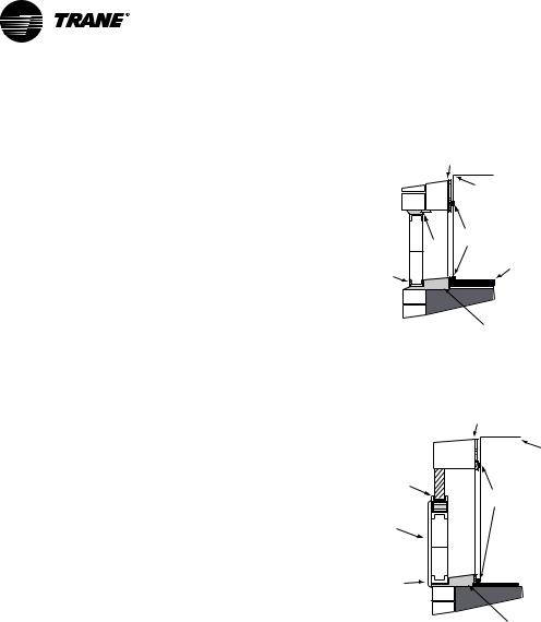
Installation in Masonry Walls. A typical method of installing the wall box in a masonry wall opening is shown in Figure 9.
Grout the top and bottom of the wall box frame as noted. A sloped water dam located in the space between the unit and wall facilitates moisture drainage. Grouting at the ends of the intake box will complete the seal between the wall box frame and the masonry opening.
Installation in Curtain Walls. In all cases, the wall intake box should be caulked to provide a tight, weatherproof seal (see Figure 10).
Note: A minimum of 2-1/8 in. of clearance must be maintained between the exterior wall and back of the unit. Failure to provide this gap will not allow the wall box to fit properly.
Figure 9. Masonry wall installation
Interior Wall w/ sheetrock
Outside |
|
Unit |
Wall |
|
|
|
|
|
|
|
Rubber |
|
Grout |
Seals |
|
|
|
Weep |
|
Floor |
Holes |
|
|
Water dam sloped toward exterior
Figure 10. Flanged wall box installation in 2-in. curtain wall
Interior Wall w/ sheetrock
Outside |
|
Wall |
Unit |
Caulking
Rubber
Seals
Flanged wallbox
Weep
Holes
Water dam sloped toward exterior
General Installation Checks
The checklist below is a summary of the steps required to successfully install a unit. This checklist is intended to acquaint the installing personnel with procedures required in the installation process. It does not replace the detailed instructions called out in the applicable sections of this manual.
1.Carefully remove the stretch wrap and top cardboard cover. Check the unit for shipping damage and material shortage; file a freight claim and notify appropriate sales representation. If end panels have been ordered, the panel will already be mounted to the unit.
Note: The unit ventilator is packaged in clear stretch wrap to allow for immediate visual inspection. A protective cardboard cover helps prevent scratching and other cosmetic blemishes during transport.
2.Remove remaining cardboard blocking.
3.Remove the unit’s left front panel to verify nameplate/ sales order number is correct. It is located behind the control box.
20 |
UV-SVN03F-EN |
Installation—Mechanical
4.Remove shipping bracket from the lower rear corners of the unit to separate the unit from the skid. Access to the screws holding the bracket to the skid is obtained inside the unit.
5.Rotate the fan wheels manually. The wheels should move freely and be in proper alignment. Visually inspect the fan area for obstructions or shipping damage.
6.Remove all applicable knockouts for coil piping and electrical connections.
Location Considerations
Selecting the appropriate location for installing a unit is very important. The following factors should be considered:
 WARNING
Heavy Object!
Floor structure must be strong enough to support the weight of the unit. Consult the structural plans, and have a structural engineer ensure the floor can withstand the weight of the unit. Inadequate structural support could result in unit falling.
Failure to follow recommendations could result in death or serious injury.
1.Floor design must have sufficient structure to withstand the weight of the unit while allowing for openings in the floor for a return air duct, electrical and piping supply lines fed through the floor. Refer to “Dimensions and Weights,” p. 11 for unit weights.
2.Wall space design should allow the unit to be mounted to the wall securely. The wall surface behind the unit should be smooth and level. Wall and floor moldings should be removed prior to installation. A wall slightly out of level may cause problems with unconditioned air leaking into the room. Remove any object projecting more then 1/8 in. (0.3175 cm) from the wall surface.
Note: Additional gasket or furr strips may be installed to accommodate for an uneven wall.
3.There are two removable knock-outs in the rear of the unit, on either end, for piping and electrical supply lines. A pipe chase is located in the upper back portion of the unit for crossover piping. The outside air opening is located in the lower back of the unit and the path to the wallbox on the outside wall should be unobstructed.
4.The physical layout of the room should accommodate any accessories ordered with the unit. Conditioned air is distributed through the grille on top of the unit and returned through the return air grille on the bottom of the unit. Avoid placing any objects that may obstruct either grille or interfere with airflow.
5.Internal access to the unit is provided by the removable front panel. Sufficient space should be allowed to lift the panel for maintenance purposes.
6.Ensure the floor surface is level.
Note: The unit leveling legs can be adjusted to accommodate slight out-of-level installation surfaces.
Unit Mounting
Note: All wall intake boxes should be installed prior to mounting the unit ventilator. Refer to p. 20 for wall box installation instructions.
The 1/2 in. mounting or anchoring holes are located on the back of the unit on each end (see Figure 11, p. 22).
Note: All mounting fasteners are to be provided by the installer.
UV-SVN03F-EN |
21 |

Installation—Mechanical
Figure 11. Mounting hole location
E |
F |
C |
C |
|
B |
B |
|
 A
A D
D
|
|
A |
B |
C |
D |
E |
F |
075 |
Standard unit (no falseback) |
1.31 |
13.50 |
2.75 |
66.39 |
10.38 |
45.64 |
|
Standard falseback |
1.00 |
2.13 |
26.00 |
67.00 |
10.00 |
47.00 |
|
29 in. stepdown falseback |
1.00 |
2.13 |
24.44 |
67.00 |
10.00 |
47.00 |
|
28 in. stepdown falseback |
1.00 |
2.13 |
23.44 |
67.00 |
10.00 |
47.00 |
|
27 in. stepdown falseback |
1.00 |
2.13 |
22.44 |
67.00 |
10.00 |
47.00 |
|
26 in. stepdown falseback |
1.00 |
2.13 |
21.44 |
67.00 |
10.00 |
47.00 |
|
25 in. stepdown falseback |
1.00 |
2.13 |
20.44 |
67.00 |
10.00 |
47.00 |
100 |
Standard unit (no falseback) |
1.31 |
13.50 |
2.75 |
78.39 |
10.38 |
57.64 |
|
Standard falseback |
1.00 |
2.13 |
26.00 |
79.00 |
10.00 |
59.00 |
|
29 in. stepdown falseback |
1.00 |
2.13 |
24.44 |
79.00 |
10.00 |
59.00 |
|
28 in. stepdown falseback |
1.00 |
2.13 |
23.44 |
79.00 |
10.00 |
59.00 |
|
27 in. stepdown falseback |
1.00 |
2.13 |
22.44 |
79.00 |
10.00 |
59.00 |
|
26 in. stepdown falseback |
1.00 |
2.13 |
21.44 |
79.00 |
10.00 |
59.00 |
|
25 in. stepdown falseback |
1.00 |
2.13 |
20.44 |
79.00 |
10.00 |
59.00 |
125 |
Standard unit (no falseback) |
1.31 |
13.50 |
2.75 |
90.39 |
10.38 |
69.64 |
|
Standard falseback |
1.00 |
2.13 |
26.00 |
91.00 |
10.00 |
71.00 |
|
29 in. stepdown falseback |
1.00 |
2.13 |
24.44 |
91.00 |
10.00 |
71.00 |
|
28 in. stepdown falseback |
1.00 |
2.13 |
23.44 |
91.00 |
10.00 |
71.00 |
|
27 in. stepdown falseback |
1.00 |
2.13 |
22.44 |
91.00 |
10.00 |
71.00 |
|
26 in. stepdown falseback |
1.00 |
2.13 |
21.44 |
91.00 |
10.00 |
71.00 |
|
25 in. stepdown falseback |
1.00 |
2.13 |
20.44 |
91.00 |
10.00 |
71.00 |
150 |
Standard unit (no falseback) |
1.31 |
13.50 |
2.75 |
102.39 |
10.38 |
81.64 |
|
Standard falseback |
1.00 |
2.13 |
26.00 |
103.00 |
10.00 |
83.00 |
|
29 in. stepdown falseback |
1.00 |
2.13 |
24.44 |
103.00 |
10.00 |
83.00 |
|
28 in. stepdown falseback |
1.00 |
2.13 |
23.44 |
103.00 |
10.00 |
83.00 |
|
27 in. stepdown falseback |
1.00 |
2.13 |
22.44 |
103.00 |
10.00 |
83.00 |
|
26 in. stepdown falseback |
1.00 |
2.13 |
21.44 |
103.00 |
10.00 |
83.00 |
|
25 in. stepdown falseback |
1.00 |
2.13 |
20.44 |
103.00 |
10.00 |
83.00 |
 WARNING
Improper Unit Lift!
Test lift unit approximately 24 inches to verify proper center of gravity lift point. To avoid dropping of unit, reposition lifting point if unit is not level. Failure to properly lift unit could result in death or serious injury or possible equipment or property-only damage.
7.Set the unit into selected location and adjust leveling legs if necessary to ensure level fit.
Note: Care should be taken when handling the unit to ensure that the front return air grille does not bend.
8.Push the unit tightly against the wall to compress the seal on the back edge of the unit and intake opening. Anchor the unit by using the 1/2 in. mounting holes in both end pockets.
Units containing a falseback: The falseback unit ventilator contains mounting holes located on the
falseback metal. Use these holes rather than the holes located in the unit’s end pockets.
Note: Ensure the unit is level. Coils and drain pans inside the unit are pitched properly for draining before shipment.
9.Ensure the unit rests tightly against the wall. Check for proper seal and that air does not leak underneath the unit.
Subbase (Option)
A subbase may be used to increase the unit height and aid in leveling the unit. The subbase is shipped separately for field installation. Slots and leveling screws are provided on the subbase.
1.Remove the leveling legs provided with the unit (see Figure 12).
22 |
UV-SVN03F-EN |

Installation—Mechanical
Figure 12. Subbase with leveling legs
Unit Base
 Weld
Weld
Nuts
2"- 6" Subbase
For leveling legs
2.Set the unit on the subbase and fasten with four, 3/8 in. x 16 ft x 1 in. hex head cap screws and 3/8 in. lock washers.
Note: Hex screws and lock washers are provided by the factory. They are located in a baggy and are used to attach the base to the unit ventilator.
Pre-drilled slots in the subbase flange will line up with the weld nuts in the bottom of the unit.
3.The bottom of the subbase has weld nuts in four slots. Place the leveling legs in those slots and level the unit.
End Panels
When ordered as an option, end covers ship already attached to the vertical unit ventilator. The following section is for installing end covers purchased as an addon.
It is recommended end panels be installed on the unit ventilator after all piping, wiring and accessory installation is completed. To install the end panel:
1.Insert the four factory provided metal studs into the four pre-mounted nuts on the inside of the panel.
2.Align each stud with the four pre-drilled holes on the side of the unit.
3.Secure the panel to the unit by fastening with the four factory provided nuts.
4.Do not overtighten screws.
NOTICE:
Equipment Damage!
Do not run units for any length of time without all panels and filters properly installed. Failure to do so could result in equipment failure.
UV-SVN03F-EN |
23 |

Installation—Piping
Piping Installation
Before installation of piping package, the shipping bracket holding the piping in place, must be removed.
Proper installation of piping is necessary to provide efficient coil operation and to prevent damage during operation. Follow standard piping practices and include all accessories as necessary.
Piping connection knockouts are shown in “Dimensions and Weights,” p. 11. Field connection types and sizes for unit coils are listed in Table 8. These sizes are provided for field piping connection.
Table 8. |
Coil data for field piping |
|
|
|
|
|
|
Coil type |
|
Connection location |
Field connection size |
|
|
|
|
4-pipe chilled water / |
Left or right (opposite |
7/8 in. OD / 5/8 in. OD |
|
hot water |
|
ends) |
|
|
|
|
|
2-pipe changeover coil |
Left or right |
7/8 in. OD |
|
|
|
|
|
Hot water only |
Left or right |
7/8 in. OD |
|
|
|
|
|
Steam |
|
Left or right |
1 in. MPT |
|
|
|
|
Chilled water / electric |
Left cooling |
7/8 in. OD |
|
heat |
|
|
|
|
|
|
|
Chilled water / steam |
Left or right |
7/8 in. OD / 1 in. MPT |
|
|
|
|
|
DX |
|
Left |
7/8 in. suction, 3/8 in. |
|
|
|
|
DX / hot water |
Left cooling / right |
7/8 in. suction, |
|
|
|
heating |
3/8 in. / 5/8 in. OD |
|
|
|
|
DX / steam |
|
Left cooling / right |
7/8 in. suction, |
|
|
heating |
3/8 in. / 1 in. MPT |
|
|
|
|
DX / electric heat |
Left cooling / right |
7/8 in. suction, |
|
|
|
heating |
3/8 in. / NA |
|
|
|
|
A 7/8 in. OD condensate drain connection is provided on the chilled water supply end of the unit.
1.Attach a flexible condensate drain hose over the drain pan connection and secure with a hose clamp.
The drain pan on the vertical is vacuum-molded with a drain connection and P-trap on the cooling coil, connection side.
Note: Condensate removal to the main system should be made through the bottom of the unit ventilator. If other location for condensate removal is desired, a specific field cut-out for the connection should be made in the back of the unit ventilator. To help avoid cold air infiltration, the field cut-out should only be large enough to allow for the condensate hose to exit the unit.
To field reverse the slope of a vertical unit drain pan:
2.Slide out fan deck (disconnecting the condensate line and fan plug will release fan deck for sliding).
3.Remove pipe clamp that hold the p-trap to the drain pan.
4.Remove clips that hold the drain pan in-place.
5.Lift and rotate the drain pan.
6.Reconnect p-trap to the drain pan and replace clips to secure the pan to the fan deck.
7.After the condensate drain piping has been completed, check water flow to ensure the system properly carries and away all condensate accumulation.
Note: A P-trap is factory supplied in every vertical unit ventilator.
Trane Piping Packages (Option). Trane Standard Piping Package includes a 2- or 3-way valve with bypass balance valve, ball valves, Pete’s plugs and unions. A strainer and circuit balancing valve are optional.
All union connections should be tightened in the field. Units are shipped with union connections hand tightened only in the factory.
Note: All connections made in the field should be sweat connections.
Piping packages are not shipped insulated. Any insulation should be provided in the field by the installing contractor.
The auxiliary drain pan (optional) is the main condensate connection to the unit when specified. The chilled water or DX coil drain pan will empty into the auxiliary drain pan if a factory-installed, auxiliary pan is ordered. All field-piping condensate connections should be made at the auxiliary drain pan.
Installation Crossover Piping
Crossover piping is available for all hydronic coils. It is either 1-3/8 in. \[34.9\] or 2-1/8 in. \[54\] in diameter (OD) as specified by the customer. Crossover piping can be found in either the left or right hand end pocket. Refer to “Dimensions and Weights,” p. 11 for dimensional data.
On 4-pipe coils, crossover piping connects to the main cooling coil.
Factory insulation is provided on all crossover piping.
When a Trane piping package is ordered, it is installed with the connections made to the supply and return of both the coil and the crossover piping. However, supply and return connections must be made in the field when a piping package is furnished by the installer.
The crossover piping is located at the back of the unit along the wall and the ends of the piping are flush with the end of the unit.
Expansion compensation between the piping package and the crossover piping is achieved using flex hoses rated at 250 psi working pressure. Expansion compensation for the crossover piping must be handled external to the unit ventilator.
Split System Units
The following refrigerant piping and interconnecting wiring instructions apply to unit ventilators with direct expansion type cooling coils used in conjunction with aircooled condensing units. Reference must also be made to
24 |
UV-SVN03F-EN |

Installation—Piping
the condensing unit installation and wiring manuals which are shipped with the condensing unit.
Note: The ETL listing mark applied to a unit ventilator does not apply to any associated refrigerant condensing unit.
Refrigerant Piping
 WARNING
Hazard of Explosion and Deadly Gases!
Never solder, braze or weld on refrigerant lines or any unit components that are above atmospheric pressure or where refrigerant may be present. Always remove refrigerant by following the guidelines established by the EPA Federal Clean Air Act or other state or local codes as appropriate. After refrigerant removal, use dry nitrogen to bring system back to atmospheric pressure before opening system for repairs. Mixtures of refrigerants and air under pressure may become combustible in the presence of an ignition source leading to an explosion. Excessive heat from soldering, brazing or welding with refrigerant vapors present can form highly toxic gases and extremely corrosive acids. Failure to follow all proper safe refrigerant handling practices could result in death or serious injury.
Unit ventilators with direct expansion cooling contain a nitrogen holding charge in the evaporator coils. Connections are “pinched-off” at the factory.
To connect the condensing unit lines, cut off the stubouts and swage. The condensing unit lines can then be brought into the swage and brazed. Trane recommends the use of nitrogen purge when brazing refrigerant lines to prevent formation of oxides in the lines.
Install the refrigerant suction and liquid lines as described in the condensing unit installation instructions. The TXV is factory installed on the unit ventilator. Piping should be run straight out through the back of the unit. Access piping knockouts are located in the rear panels of the unit, as shown “Dimensions and Weights,” p. 11.
Recommended refrigerant line connections for various unit combinations are given in Table 8, p. 24. Typical Superheat Charging Charts are shown in the Trane Service Facts found in the condensing unit section manual. Refrigerant charge weights can also be determined with your local Trane sales engineer using a valid Trane Selection Program.
Steam Piping
When air, water or another product is heated, the temperature or heat transfer rate can be regulated by a modulating steam pressure control valve. Since pressure and temperature do not vary at the same rate as load, the steam trap capacity, which is determined by the pressure differential between the trap inlet and outlet, may be adequate at full load, but not some lesser load.
There are detailed methods for determining condensate load under various operating conditions. However, in most cases this is not necessary if the coils are piped as shown in Figure 13. Follow the procedure documented in the ASHRAE Systems Handbook, Steam Systems.
Figure 13. Steam piping
Temp. Regulating Valve
|
Coil |
To Condensate |
|
return |
H= 12" |
|
minimum |
|
Vacuum Equalizer |
|
F&TTrap |
|
See text for sizing |
Gravity flow to vented receiver
Modulating Water Valves (Option)
The actuator on the valve is a 24V, 3-point floating valve. The actuator can be easily removed from the valve body by pressing in on the locking tab and rotating the actuator 45° counter-clockwise (see Figure 14). The 2-way valves are bi-directional flow; the 3-way valves can be mixing or diverting (see Figure 15, p. 26).
Note: The actuator must be removed if soldering is being conducted near the valve. High heat may cause damage to the actuator’s plastic body/ mechanisms.
Figure 14. Remove modulating valve actuator by pressing in tab (inset) and turning actuator 45° counterclockwise
UV-SVN03F-EN |
25 |
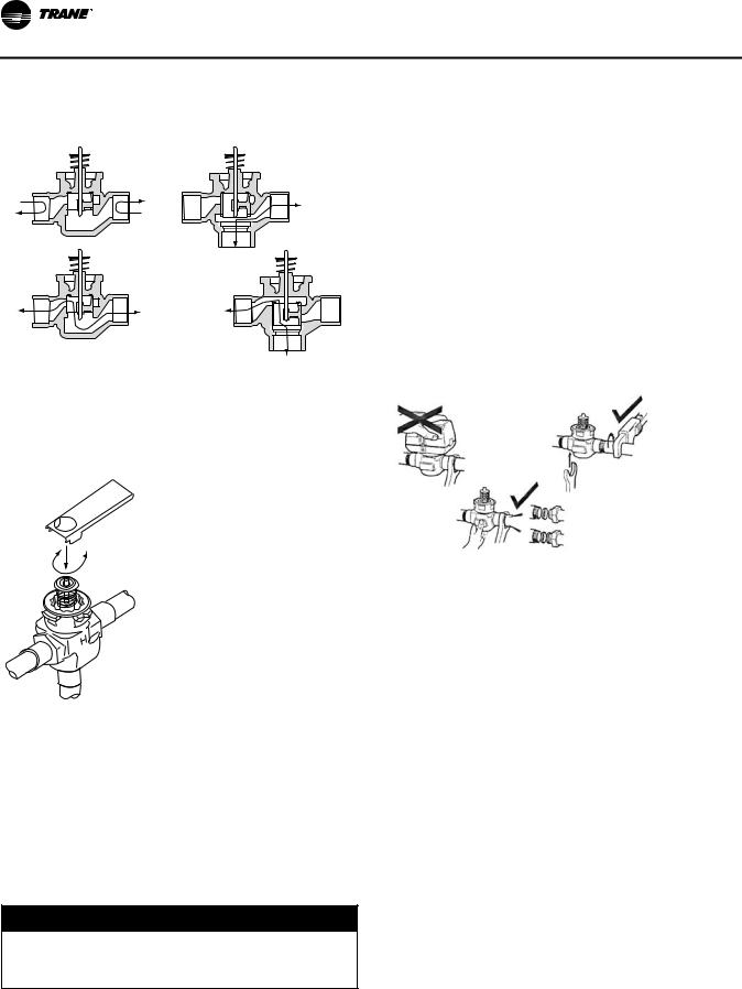
Installation—Piping
Figure 15. Steam piping: 2- and 3-way valves
2-way valve |
|
3-way valve |
|
Closed |
AB<->B |
A |
B |
B |
|
|
|
|
Open |
AB |
|
|
|
|
|
AB<->A |
A |
B |
A |
|
AB
On applications without the optional, factory installed piping packages, it is important to remove the cartridge assembly from the valve body with the provided tool (see Figure 16).
Figure 16. Cartridge removal tool
Plumbing the Valve
The valve may be plumbed in any angle but preferably not with the actuator below horizontal level of the body. Make sure there is enough room around the actuator for servicing or replacement.
For use in diverting applications, the valve is installed with the flow water entering through the bottom AB port and diverting through end ports A or B. In mixing applications the valve is installed with inlet to A or B and outlet through AB.
Mount directly to the tube or pipe. Do not grip the actuator while making or tightening plumbing connections. Either hold valve body by hand or attach an adjustable spanner (38 mm/1-1/2”) across the hexagonal or flat faces on the valve body (see Figure 17).
Figure 17. Proper plumbing technique for modulating valves
Use the following steps to complete cartridge assembly removal:
1.Remove valve actuator.
2.Remove the cartridge assembly from the valve body with the enclosed tool.
3.Solder the valve in accordance with normal soldering practices.
4.Re-install the cartridge after soldering by tightening until it bottoms out. The top surface of the cartridge will be flush with the top edge of the body casting.
NOTICE:
Over-tightening!
Do not over-tighten. Maximum torque is 40 in·lb. Overtightening could result in equipment damage.
5.Replace valve actuator and wire in accordance with instructions.
Manually Opening Valve
The manual opener can be manipulated only when in the up position. The A port can be manually opened by firmly pushing the white manual lever down to the midway position and pushing the lever in. In this position, both A and B ports are open. This “manual open” position may be used for filling, venting and draining the system or opening the valve during power failure.
The valve can be closed by depressing the white lever lightly and then pulling the lever outward. The valve and actuator will return to the automatic position when power is restored.
Note: If the valve is powered open, it cannot be manually closed, unless the actuator is removed.
26 |
UV-SVN03F-EN |

Installation—Piping
Wiring the Valve
 WARNING
Electrocution and Fire Hazards with Improperly Installed and Grounded Field Wiring!
Improperly installed and grounded field wiring poses FIRE & ELECTROCUTION hazards. To avoid these hazards, you MUST follow requirements for field wiring installation and grounding as described in NEC and your local/state electrical codes. All field wiring MUST be performed by qualified personnel.
Failure to follow these requirements could result in death or serious injury.
A controller and a separate transformer is required to operate each valve (see Figure 18 and Figure 19, p. 27). Port A “open” and “closed” denote valve open and closed positions.
Figure 18. Wiring for modulating valve actuator
Figure 19. Wiring for modulating valve actuator
The typical floating controller is an SPDT controller with a center-off position. On a change in temperature from the set point, the controller will close the normally open (NO) or normally closed (NC) contacts, driving the valve to an intermediate position until a further change at the controller.
The valve is set between the limits of the controller to satisfy various load requirements. In the event of power failure, the valve will stay in the position it was in before loss of power. When power is restored, the valve will again respond to controller demand.
Isolation Valves Installation
The valve can be mounted in any position on a vertical line. If the valve is mounted horizontally, the actuator must be even with or above the center line. Make sure there is
enough room to remove actuator cover for servicing. Mount the valve on the tube or pipe.
Note: Ensure the flow through the valve is in the direction indicated by the arrow stamped on the valve body.
Figure 20. Proper mounting for isolation valves
Servicing/Removal of Valves
The actuator can be removed from the valve body. Removing the actuator is recommended if soldering is being conducted near the valve. To remove the actuator:
1.Place the manual operating lever to the Open position (see Figure 21, p. 27).
2.Depress the locking button and lift actuator until it separates from the valve body.
To install the actuator to the valve body:
3.Align the slot on the shaft of the valve with the valve body notch on side of body (see Figure 22, p. 28).
Figure 21. Removing valve actuator
UV-SVN03F-EN |
27 |

Installation—Piping
Figure 22. Installing isolation valve
Figure 23. Preparation for soldering
4. Install body valve into pipe.
 WARNING
Electrocution and Fire Hazards with Improperly Installed and Grounded Field Wiring!
Improperly installed and grounded field wiring poses FIRE & ELECTROCUTION hazards. To avoid these hazards, you MUST follow requirements for field wiring installation and grounding as described in NEC and your local/state electrical codes. All field wiring MUST be performed by qualified personnel.
Failure to follow these requirements could result in death or serious injury.
5.Wiring connections may be made either before or after actuator installed on body.
6.Place the manual operating lever on the actuator in the OPEN position.
7.Align actuator coupling to slot on the shaft of the valve body and fit the head onto the valve body to ensure the shaft seats correctly (see Figure 20, p. 27).
8.Press the actuator and valve body until it secures together.
Soldering Procedures
1.Remove actuator as stated earlier.
2.Place valves on the pipe. Rotate valve stem so the shaft slot points at the notch in the side of the body (90° to flow direction). This protects the plug inside the valve by removing it from the seat (see Figure 23).
3.Sweat the joints, keeping outer surface free from solder.
Note: Do not use silver solder due to high temperature requirements.
Heating Coils with Direct Expansion Cooling
Heating options for direct expansion cooling in the unit ventilator are hot water, steam or electric heat.
These coils facilitate direct expansion cooling with standard capacities. The supply and return connections are located in the right-hand end pocket. Hot water field connections are made with a 5/8 in. \[15.9\] OD male sweated joint, while steam coils have a 1 in. \[25.4\] male pipe thread (MPT) connection. Refer to Table 8, p. 24 for coil connection sizes.
Electric heat coils provide a third way to supply heating to the direct expansion cooling. The coil utilizes three to six preheat elements which are factory-wired.
28 |
UV-SVN03F-EN |

Installation—Sensors
Control Options
Figure 24. Unit mtd temp sensor
(SP, OCC/UNOCC, OALMH)
(Electric heat with auto and off speeds)
X13790844-01 (unit)
Figure 25. Unit mtd display sensor (SP, OCC/UNOCC, COMM)
X13790886-04 (unit; 3-speed)
Figure 26. Unit mtd display sensor (SP, OCC/UNOCC, COMM)
X13790886-03 (unit; 2-speed)
Figure 28. Wall mtd display sensor (SP, OCC/UNOCC, COMM)
X13790886-04 (wall; 3-speed)
Figure 29. Wall mtd display sensor (SP, OCC/UNOCC, COMM)
X13790886-03 (wall; 2-speed)
Figure 30. Unit mtd FSS (OALMH), wall mtd temp sensor (SP, OCC/UNOCC, COMM)
X13511527-01 (wall)
X13790849-01 (unit)
X13651467-01 (comm)
Figure 27. Wall mtd temp sensor
(SP, OCC/UNOCC, OALMH, COMM)
X13790842-02 (wall)
X13651467-01 (comm)
Figure 31. Unit mtd FSS (OALMH),
wall mtd display temp sensor (SP, OCC/UNOCC, COMM)
X13790886-04 (wall)
X13790841-02 (unit)
UV-SVN03F-EN |
29 |

Installation—Sensors
Figure 32. Unit mtd FSS (OLH),
wall mtd display temp sensor (SP, OCC/UNOCC, COMM)
X13790886-03 (wall)
X13790475-01 (unit)
Installing Wall-Mounted Wired
Sensors
Reference the wall-mounted zone sensor dimensions in Figure 36, p. 30. Position the sensor on an inside wall three to five feet above the floor and at least 18 inches from the nearest outside wall. Installing the sensor at a lower height may give the advantage of monitoring the temperature closer to the zone, but it also exposes the sensor to airflow obstructions. Ensure that air flows freely over the sensor.
Figure 36. Wall-mounted wired and wireless zone sensor dimensions
|
|
|
1 |
|
2 |
Figure 33. Wireless temp sensor |
|
|
|
||
|
|
|
|
||
|
(SP, OCC/UNOCC, OALMH, COMM) |
|
|
|
|
|
|
|
4 |
|
3 |
|
|
|
|
5 |
|
|
|
|
6 |
|
|
|
|
|
|
|
|
|
X13790492-01 (wall) |
|
|
|
|
|
X13790855-01 (unit) |
|
|
|
|
|
|
|
7 |
|
|
Figure 34. |
Wireless temp sensor with display |
8 |
|
|
9 |
|
(SP, OCC/UNOCC, COMM) |
|
|
|
|
|
|
|
|
|
|
|
X13790822-04 (wall) |
|
0 |
|
|
|
|
|
|
|
|
|
X13790855-01 (unit; 3-speed) |
|
|
|
|
|
|
|
- |
|
|
|
|
|
= |
|
|
Figure 35. Wireless temp sensor with display |
1. |
0.31 in |
7. |
3.39 in |
|
|
(SP, OCC/UNOCC, COMM) |
2. |
TYP R.07 in (R1.9) |
8. |
4.68 in |
|
|
3. |
TYP 0.24 in) |
9. |
2.48 in |
|
|
4. |
2.9 in |
10. |
0.63 in |
|
X13790822-01 (wall) |
5. |
1.08 in |
11. |
1.45 in |
|
6. |
0.12 in |
12. |
2.62 in |
|
|
X13790855-01 (unit; 2-speed) |
Sensor |
|
|
|
|
|
|
|
||
|
|
When selecting a sensor location, avoid the following: |
|||
|
|
• Areas of direct sunlight |
|
|
|
|
|
• Areas in the direct airstream of air diffusers |
|||
|
|
• Exterior walls and other walls that have a temperature |
|||
|
|
|
differential between the two sides |
||
30 |
UV-SVN03F-EN |
Loading...