


 Loading...
- Data Brochure |
D 363 |
Universal Reset Control 363 |
12/08 |
TheUniversalResetControl363isamicroprocessorbasedcontroldesignedtomaximizethecomfortandefficiencyprovidedbyahydronic heating system. The control automatically adjusts the boiler and mixed loop water temperatures that are delivered to the heating system by using outdoor reset. For a mixing device, the 363 can use a variable speed driven wet-rotor circulator or a floating action driven mixing valve. The 363 is capable of controlling an indirect Domestic Hot Water (DHW) storage tank and / or a setpoint load. The temperature of individual zones can be controlled by connecting a conventional thermostat system or a tekmar Zone Control to the 363.
The 363 control includes a large Liquid Crystal Display (LCD) in order to view system status and operating information. The LCDand user key pad are used to set the control’s adjustment and to monitor pump and boiler running hours, DHW tank temperatures, outdoor and system high and low temperatures, boiler firing cycles, plus many other useful items.
Several energy saving features have been incorporated into the 363 such as Warm Weather Shut Down (WWSD), DHW post purge, system setback, DHW priority, Morning Boost, Soft Start and an automatic differential for boiler control. The 363 also has a unique feature that allows the control to supply heat to the mixed system from either the boiler or a thermal storage tank.
Note:
Boiler, DHW, setpoint, or mix demand must be powered with 20 to 260 V (ac) before the control will operate pump/valve outputs or the boiler is able to fire.
Input
Mix Demand signal
Input
Boiler Demand 

signal
Input
Setpoint or DHW Demand signal
Input
120 V (ac)
Power
Supply
Output
Boiler System
Pump
 M
M
Output
DHW Pump OR
DHW Valve
|
|
|
Setback |
Reset Ratio |
|
|
|
View |
|
Mix Demand |
|
Characterized |
|
|
|
|
|
Boiler Demand |
None |
|
|
|
|
|
|
Heating Curve |
|
|
|
||
|
°F |
DHW Demand |
|
|
|
|
|
|
|
|
|
|
|
||
|
|
Setpoint Demand |
|
|
Test |
|
|
|
|
WWSD |
|
|
|
|
|
|
1 2 |
|
|
|
|
|
|
% |
Minimum |
|
|
|
|
|
|
1 |
DHW |
|
|
off |
not testing |
||
|
|
Maximum |
|
|
|||
|
|
|
|
red |
testing |
|
|
|
|
|
|
|
|
||
|
|
|
|
|
red |
testing paused |
|
|
|
|
|
|
For maximum heat, |
|
|
|
|
|
|
|
press and hold Test |
|
|
|
|
|
See product literature |
button for 3 seconds. |
|||
|
|
|
INSTALLATION CATEGORY II |
|
Meets Class B: |
||
Menu |
Item |
|
Made in Canada by |
|
|||
|
|
FCC Part 15 |
|
||||
|
|
|
|
|
|
Canadian ICES |
|
|
|
|
tekmar Control Systems Ltd. |
|
|
|
|
|
|
|
tektra 929-05 |
|
|
|
|
|
|
|
Power |
115 V ±10% 60 Hz 1800 VA |
|
|
|
|
|
R |
Relays |
230 V (ac) 7.5 A 1/3 hp, pilot duty 240 VA |
|
||
|
|
|
Var. Pump |
230 V (ac) 2.4 A 1/6 hp, fuse T2.5 A 250V |
Code |
||
Universal Reset Control 363 |
|
Demands |
20 to 260 V (ac) 2 VA |
|
|
||
|
|
|
|
||||
C US |
Signal wiring must be rated at least 300 V. |
|
|
Date |
|||
Mixing, Boiler & DHW |
|
|
|
|
|||
|
|
Supply wiring must be rated 90°C minimum |
|
|
|||
|
|
|
|
|
|
|
|
|
|
|
|
|
|
|
Do not apply power |
|
|
H1153E |
|
|
||
1 |
2 |
3 |
4 |
5 |
6 |
7 |
8 |
9 |
10 11 |
12 13 14 15 16 |
17 18 19 20 21 22 23 24 25 26 |
|
|
|||||||||
|
Mix |
Com Boil Setp/ |
Power |
Boil |
DHW |
Mix |
Boiler |
Pwr Opn |
Cls/ |
Com 10K |
tN1/ Com 10K |
UnO Com Mix |
Boil |
Out |
|
|
||||||
Demand |
Dem Dem DHW |
N |
L |
P1 |
Pmp / Vlv |
P2 |
|
Mix |
Var |
2 |
tN2 |
1 |
Sw |
|
|
|
|
|
||||
|
|
|
|
|
|
|
|
|
|
|
|
|
|
|
|
|
|
|
|
|
|
Input |
|
|
|
|
|
|
|
|
|
|
|
|
|
|
|
|
|
|
|
|
|
|
Outdoor |
|
|
|
|
|
|
|
|
|
|
|
|
|
|
|
|
|
|
|
|
|
|
Sensor Included |
|
|
|
|
|
|
|
|
|
|
|
|
|
|
|
|
|
|
|
|
|
Input |
|
|
|
|
|
|
|
|
|
|
|
|
|
|
|
|
|
|
|
|
|
|
Universal |
|
|
|
|
|
|
|
|
|
|
|
|
|
|
|
|
|
|
|
|
|
|
Sensor Included |
|
|
|
|
|
|
|
|
|
|
|
|
|
|
|
|
|
|
|
|
|
|
Input |
|
|
|
|
|
|
|
|
|
|
|
|
|
|
|
|
|
|
|
|
|
|
Universal |
|
|
|
|
|
|
|
|
|
|
|
|
|
|
|
|
|
|
|
|
|
|
Sensor Included |
|
|
|
|
|
|
|
|
|
|
|
|
|
|
|
|
|
|
|
|
|
|
|
Input |
|
|
|
|
|
|
|
|
|
|
|
|
|
|
|
|
|
|
|
|
|
|
tekmar |
|
|
|
|
|
|
|
|
|
|
|
|
|
|
|
|
|
|
|
|
|
|
Timer |
|
|
|
|
|
|
|
|
|
|
|
|
|
|
|
|
|
|
|
|
|
|
Input (MIX) |
|
|
|
|
|
|
|
|
|
|
|
|
|
|
|
|
|
|
|
|
|
OR |
tekmar Slab |
|
|
|
|
|
|
|
|
|
|
|
|
|
|
|
|
|
|
|
|
|
Sensor |
|
|
|
|
|
|
|
|
|
|
|
|
|
|
|
|
|
|
|
|
|
|
|
Input (MIX) |
|
|
|
|
|
|
|
|
|
|
|
|
|
|
|
|
|
|
|
|
|
|
tekmar Indoor |
|
|
|
|
|
|
|
|
|
|
|
|
|
M |
|
|
|
|
|
|
|
|
Sensor |
|
|
|
|
|
|
|
|
|
|
|
|
|
|
|
|
|
! |
OR |
! |
OR |
|
|
|
|
|
|
|
|
|
|
|
|
OR |
|
|
|
|
|
Menu Item |
Menu Item |
|
||||
|
|
|
|
|
|
|
|
|
|
|
|
|
|
Input |
|
Input (MIX) |
|
Input |
|
Input |
||
Output |
|
|
|
|
|
|
Output |
|
Output |
|
|
|
(BOIL |
|||||||||
|
|
|
|
|
|
|
Universal |
|
|
Room |
|
|
Remote |
|
or MIX) |
|||||||
Mixed System |
Output |
|
|
Var. Speed |
Mixing Valve & |
Sensor |
|
Temperature |
|
Display |
|
tekmar Zone |
||||||||||
Pump |
|
Boiler |
|
|
Driven Pump |
Actuating Motor |
(optional) |
|
Unit (RTU) |
|
Module (RDM) |
|
Control |
|||||||||
1 of 40 |
Copyright © D 363 -12/08 |
How To Use The Data Brochure 


This brochure is organized into four main sections. They are: 1) Sequence of Operation, 2) Installation, 3) Control Settings, and 4)
Troubleshooting. The Sequence of Operation section has five sub sections. We recommend reading Section A: General of the Sequence of Operation, as this contains important information on the overall operation of the control. Then read the sub sections that apply to your installation.
The Control Settings section (starting at DIP Switch Settings) of this brochure describes the various items that are adjusted and displayed by the control. The control functions of each adjustable item are described in the Sequence of Operation.
Table of Contents 


User Interface .......................................... |
pg 2 |
Description of Display Elements ............ |
pg 3 |
Sequence of Operation ............................ |
pg 4 |
Section A: General ........................ |
pg 4 |
Section B: Boiler Reset................. |
pg 6 |
Section C: DHW / Setpoint .......... |
pg 9 |
Section D: Mixing Reset ............... |
pg 12 |
Section E: Storage ........................ |
pg 15 |
Installation ............................................... |
pg 16 |
Electrical Connections.................. |
pg 17 |
Testing The Wiring........................ |
pg 19 |
DIP Switch Settings .................................. |
pg 22 |
Access Levels ................................................ |
pg 22 |
Control Settings ............................................. |
pg 23 |
View Menu ........................................... |
pg 23 |
Adjust Menu ........................................ |
pg 24 |
Schedule Menu ................................... |
pg 28 |
Miscellaneous Menu .......................... |
pg 29 |
RTU Menu ........................................... |
pg 29 |
Testing and Troubleshooting ...................... |
pg 31 |
Monitor Menu ...................................... |
pg 33 |
Error Messages .................................. |
pg 35 |
Technical Data ............................................... |
pg 40 |
Limited Warranty ........................................... |
pg 40 |
Reference Material: Essay E 003: Characterized Heating Curve and Reset Ratio
E 021: Mixing Methods and Sizing of Variable Speed Injection Pumps
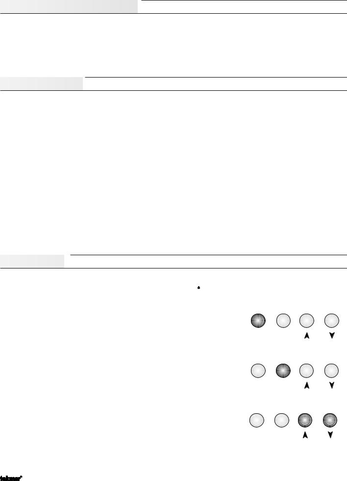
User Interface


The 363 uses a Liquid Crystal Display (LCD) as the method of supplying information. You use the LCD in order to setup and monitor the operation of your system. The 363 has four push buttons (Menu, Item, , ) for selecting and adjusting settings. As you program your control, record your settings in the Adjust Menu table which is found in the second half of this brochure.
Menu
All of the items displayed by the control are organized into various menus. These menus are listed on the left hand side of the display (Menu Field). To select a menu, use the Menu button. By pressing and releasing the Menu button, the display will advance to the next available menu. Once a menu is selected, there will be a group of items that can be viewed within that menu.
Item
The abbreviated name of the selected item will be displayed in the item field of the display. To view the next available item, press and release the Item button. Once you have reached the last available item in a menu, pressing and releasing the Item button will return the display to the first item in the selected menu.
Adjust
To make an adjustment to a setting in the control, begin by selecting the appropriate menu using the Menu button. Then select the desired item using the Item button. Finally, use the
 and / or
 button to make the adjustment.
Menu Item
Menu Item
Menu Item
Additional information can be gained by observing the Status and Pointers fields of the LCD. The status field will indicate which of the control’s outputs are currently active. Most symbols in the status field are only visible when the View Menu is selected.
Copyright © D 363 -12/08 |
2 of 40 |
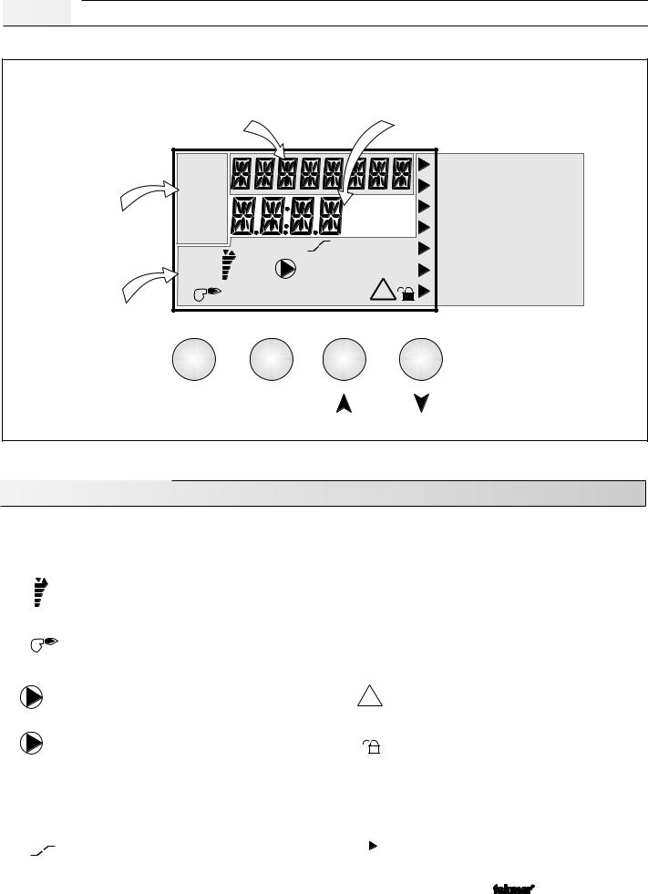
Display


Item Field |
Number Field |
Displays an abbreviated |
Displays the current value |
name of the selected item |
of the selected item |
Menu Field
Displays the current menu
Status Field
Displays the current status of the control’s inputs, outputs and operation
View |
|
|
|
|
Mix Demand |
Adjust |
|
|
|
|
Boiler Demand |
Monitor |
|
|
|
|
|
|
|
°F °C |
|
DHW Demand |
|
|
|
|
|
||
Schd |
|
|
min hr |
Setpoint Demand |
|
Misc |
|
Aux |
sec |
|
|
|
UnOcc |
Ovr |
WWSD |
||
Open |
|
||||
% |
|
1 2 |
|
Minimum |
|
Close |
1 |
|
DHW |
|
|
|
|
|
! |
|
Maximum |
|
|
|
|
|
Buttons |
|
|
|
|
|
Selects Menus, Items and |
Menu |
|
Item |
|
|
{adjusts settings |
|
|
|
|
||
Symbol Description
Open |
Open / Close |
|
|
|
UnOccupied Schedule |
|
Displays when the actuator is opening or closing |
UnOcc |
|||||
Close |
Displays when the control is in unoccupied |
|||||
the mixing valve. |
|
|
|
|||
|
|
|
|
|
mode. |
|
|
Mixing Device Output Scale |
Occ |
Occupied Schedule |
|||
% |
Shows output of injection pump or mixing valve. |
|||||
Displays when the control is in occupied mode. |
||||||
1 |
Arrows show whether the output is increasing |
|
|
|
||
|
|
|
|
|||
|
or decreasing. |
|
|
|
|
|
|
Burner |
Ovr |
Override |
|||
|
Displays when the control is in override mode. |
|||||
|
Displays when the boiler relay is turned on. |
|
|
|
||
|
|
|
|
|
||
|
|
|
|
|
|
|
1 2 |
Pump |
! |
|
Warning |
||
Displays when the boiler pump 1 and / or mixing |
|
|||||
|
|
Displays when an error exists or when a limit |
||||
|
pump 2 is operating. |
|
|
|
has been reached. |
|
|
|
|
|
|
|
|
|
DHW Pump / Valve |
|
|
|
Lock - Unlock |
|
DHW |
Displays when the DHW pump or valve is on. |
|
|
|
Displays whether the access levels are locked |
|
|
|
|
|
|
or unlocked. |
|
|
|
|
|
|
|
|
|
Storage Operation |
°F, °C, sec, |
°F, °C, sec, min, hr |
|||
Aux |
Displays when the variable speed driven injection |
|||||
Units of measurement. |
||||||
|
pump is drawing heat from the storage tank. |
min, hr |
||||
|
|
|
|
|
|
|
|
Boost |
|
|
|
Pointer |
|
|
Displays when the control is in boost after |
|
|
|
Displays the control operation as indicated by |
|
|
setback. |
|
|
|
the text. |
|
|
|
|
|
|
|
|
3 of 40 |
Copyright © D 363 -12/08 |
Sequence of Operation


Section A |
Section B |
Section C |
Section D |
Section E |
General Operation |
Boiler Reset |
Domestic Hot |
Mixing Reset |
Storage |
|
|
Water/Setpoint |
|
|
Page 4 - 6 |
Page 6 - 8 |
Page 9 - 11 |
Page 12 - 15 |
Page 15 -16 |
Section A —General Operation
POWERING UP THE CONTROL
When the Universal Reset Control 363 is powered up, the control displays the control type number in the LCD for 2 seconds. Next, the software version is displayed for 2 seconds. Finally, the control enters into the normal operating mode and the LCD defaults to displaying the current outdoor air temperature.
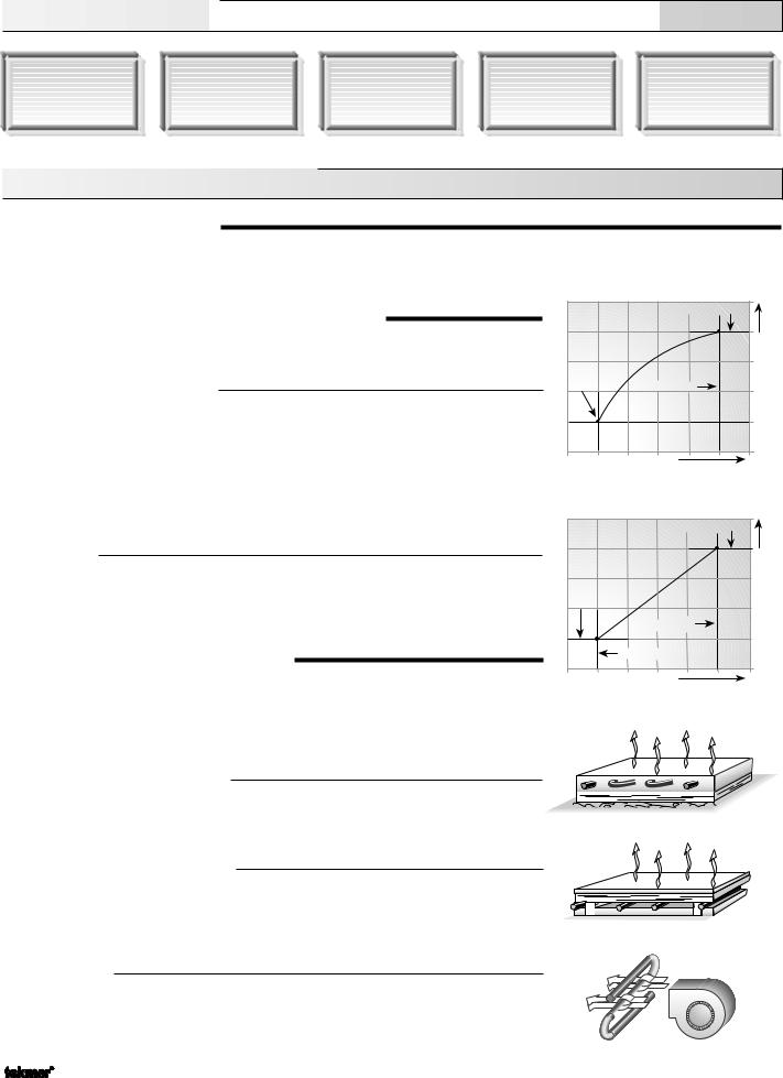
CHARACTERIZED HEATING CURVE OR RESET RATIO
The 363 has two methods of varying the supply water temperature based on the outdoor air temperature. The installer can select either a Characterized Heating Curve or a Reset Ratio.
Characterized Heating Curve
The Characterized Heating Curve method of controlling the supply water temperature based on outdoor air temperature and optionally indoor temperature is the most accurate. The control takes into account the type of terminal unit that the system is using. Since different types of terminal units transfer heat to a space using different proportions of radiation, convection and conduction, the supply water temperature must be controlled differently. Once the control is told what type of terminal unit is used, the control varies the supply water temperature according to the type of terminal unit. This improves the control of the air temperature in the building.
Reset Ratio
The Reset Ratio method of controlling the supply water temperature is based solely on the outdoor air temperature. This method does not take into account the type of terminal unit that the heating system is using and therefore is not as accurate as a Characterized Heating Curve.
TERMINAL UNITS (Boil TERM / MIX TERM)
When using a Characterized Heating Curve, the control requires the selection of a terminal unit. The terminal unit determines the shape of the Characterized Heating Curve according to how the terminal unit delivers heat into the building space. The 363 provides for selection between six different terminal unit types: two types of hydronic radiant floor heat, fancoil, fin– tube convector, radiator, and baseboard.
Hydronic Radiant Floor (HRF 1)
HRF1 is a heavy, or high mass, hydronic radiant floor system. This type of a hydronic radiant floor is embedded in either a thick concrete or gypsum pour. This heating system has a large thermal mass and is slow acting.
Hydronic Radiant Floor (HRF 2)
HRF2 is a light, or low mass, hydronic radiant floor system. Most commonly, this type of radiant heating system is either attached to the bottom of a wood sub floor, suspended in the joist space, or sandwiched between the subfloor and the surface. This type of radiant system has a relatively low thermal mass and responds faster than a high mass system.
Fancoil (COIL)
A fancoil terminal unit or air handling unit (AHU) consists of an hydronic heating coil and either a fan or blower. Air is forced across the coil at a constant velocity by the fan or blower and is then delivered into the building space.
|
MIX or BOIL DSGN |
|
MIX or |
Temperature |
|
BOIL |
||
INDR |
||
Outdoor DSGN |
||
|
IncreasingWater |
|
Decreasing Air Temperature |
||
Characterized Heating Curve
|
MIX or BOIL DSGN |
|
MIX or |
|
Temperature |
BOIL |
|
|
STRT |
|
|
|
Water |
|
|
Outdoor DSGN |
|
|
Increasing |
|
|
OUT STRT |
|
|
|
Decreasing Air Temperature
Reset Ratio
HRF 1
HRF 2
COIL
Copyright © D 363 -12/08 |
4 of 40 |

Fin–tube Convector (CONV) |
|
A convector terminal unit is made up of a heating element with fins on it. This type of terminal |
|
unit relies on the natural convection of air across the heating element to deliver heated air |
|
into the space. The amount of natural convection is dependant on the supply water |
|
temperature to the heating element and the room air temperature. |
|
Radiator (RAD) |
CONV |
A radiator terminal unit has a large heated surface that is exposed to the room. A radiator |
|
provides heat to the room through radiant heat transfer and natural convection. |
|
Baseboard (BASE) |
|
A baseboard terminal unit is similar to a radiator, but has a low profile and is installed at the |
RAD |
base of the wall. The proportion of heat transferred by radiation from a baseboard is greater |
|
than that from a fin-tube convector. |
|
|
BASE |
SETBACK (UnOccupied)
To provide greater energy savings, the 363 has a setback capability. With setback, the supply water temperatures in the system are reduced when the building is not used (AWAY) or when the building is UnOccupied. By reducing water temperatures, air temperature
in the space can be reduced even when thermostat(s) are not turned down. This feature is |
22 23 |
enabled by setting the Setback / None DIP switch to the Setback position, and providing either |
UnO Com |
an external signal or an internal override. Note: AWAY does not require the DIP switch = |
Sw |
|
|
Setback. |
|
External UnOccupied
An external signal can place the 363 into an UnOccupied mode. Any time the UnO Sw (22) and the Com (23) terminals are shorted together, the control operates in the UnOccupied mode. When in the UnOccupied mode, the UnOcc segment is displayed in the LCD. The 363 adjusts the supply water temperature(s) based on the UnOcc settings made in the control.
Internal Overrides
The 363 has a number of setback overrides that are selected through the Schd Menu. These setback overrides have priority over any external setback signal. Any time an override is in effect, the Ovr segment displays in the LCD.
Temporary (TMPY)
If a temporary override is selected, the 363 operates in the selected override mode for 3 hours. Once completed, the control reverts to the previous operation.

 Timer Switch
Schd |
|
UnOcc |
Ovr |
Permanent (PERM)
If a permanent override is selected, the 363 operates in the selected override mode until a new override is selected.
Away (AWAY)
If the AWAY override is selected, the 363 operates with a fixed WWSD of 62˚F (17˚C) and a fixed room temperature of 62˚F (17˚C). Any DHW demand is ignored. The setpoint operation is not affected by the AWAY override.
BOOSTING (Boil BST / MIX BST)
When the control changes from the UnOccupied to the Occupied mode, it enters into a Boosting mode. In this mode, the supply water temperatures to the system are raised above their normal values for a period of time to provide a faster recovery from the building’s setback temperature. The maximum length of the boost is selected in the user interface. This setting is only available if a Characterized Heating Curve is selected; It is not available for a Reset Ratio, and not needed or available if a tekmar Zone Control is used.
Water Temperature
Boost
Boil TRG (Occupied)
Boil TRG (UnOccupied)
 UnOcc to Occ
Self Adjusting
Water Temperature
Typical settings for the BOOST function vary between 30 minutes and two hours for a building that has a fast responding heating system. For a
building that has a slow responding heating system, a setting between four
hours and eight hours is typical. After a BOOST time is selected, the setback timer must be adjusted to come out of setback some time in advance of the desired Occupied time. This time in advance is normally the same as the BOOST setting. If the building is not up to temperature at the correct time, the BOOST setting should be lengthened and the setback timer should be adjusted accordingly. If the building is up to temperature before the required time, the BOOST setting should be shortened and the setback timer should be adjusted accordingly. If the system is operating near its design conditions or if the supply water temperatures are being limited by settings made in the control, the time required to bring the building up to temperature may be longer than expected.
5 of 40 


 Copyright © D 363 -12/08
SOFT START (SOF STRT)
The SOF STRT function allows the 363 to slowly ramp the water temperature up to the required supply temperature. By allowing the temperature in the system to be adjusted slowly, the control reduces any thermal expansion noises and stresses that may be caused by a quick change in supply water temperature.
WARM WEATHER SHUT DOWN (WWSD)
When the outdoor air temperature rises above the WWSD setting, the 363 turns on the WWSD pointer in the display. When the control is in Warm Weather Shut Down, the Mixing Demand and Boiler Demand pointers are displayed if there is a demand. However, the control does not operate the heating system to satisfy these demands. The control does respond to either a DHW Demand or a Setpoint Demand and operates as described in Section C.
EXERCISING (EXERCISE)
The 363 has a built-in pump and valve exercising function. The exercising period is adjustable and comes factory set at 70 hours. If a pump or valve output on the control has not been operated at least once during every exercising period, the control turns on the output for 10 seconds. This minimizes the possibility of a pump or valve seizing during a long period of inactivity. In the case where a mixing valve is being used as the mixing device, the 363 ensures that the valve operates over its entire range at least once each exercising period.
Note: The exercising function does not work if power to the control, valves or pumps is disconnected.
Section B —Boiler Reset (Mode = —1—)
Section B1
General Boiler
Operation
Section B2
Alternate Boiler
Demands
Section B1 —General Boiler Operation


BOILER DEMAND
A boiler demand is generated by applying a voltage between 24 and 240 V (ac) across the Boil Dem (4) and Com Dem (3) terminals. Once voltage is applied, the Boiler Demand pointer is displayed in the LCD. If the 363 is not in WWSD, it closes the Boiler Pump contact which starts the boiler pump. The control turns on the Boil P1 segment in the LCD. The 363 calculates a Boil TRG supply temperature based on the outdoor air temperature and settings. The 363 then fires the boiler, if required, to achieve and / or maintain the target supply temperature.
BOILER START (Boil STRT) (RESET RATIO)
The Boil STRT temperature is the boiler supply water temperature that the heating system requires when the outdoor air temperature equals the OUT STRT air temperature setting.
OUTDOOR START (OUT STRT) (RESET RATIO)
The OUT STRT temperature is the outdoor air temperature at which the control provides the Boil STRT supply water temperature to the system.
OUTDOOR DESIGN (OUT DSGN)
(RESET RATIO & CHARACTERIZED HEATING CURVE)
The OUT DSGN is the outdoor air temperature that is the typical coldest temperature of the year where the building is located. This temperature is used when doing heat loss calculations for the building.
|
Boil MAX |
210 |
Boiler Reset |
|
(99) |
|
|
|
Ratio |
Boil DSGN |
190 |
|
|
(88) |
|
|
170 |
Boil MIN |
|
(77) |
|
150 |
|
|
|
|
|
Boil SETB |
(66)Temperature |
|
|
130 |
|
|
(54)Water |
|
OUT DSGN |
110 |
Boil STRT |
|
(43)Supply |
|
90 |
|
|
|
|
|
|
(32) |
OUT STRT |
|
|
|
|
WWSD Occ |
|
|
70 |
|||||||
|
|
|
|
|
|
||||||||||
|
|
|
|
|
|
|
|
WWSD Unocc |
|
|
(21) |
||||
|
|
|
|
|
|
|
|
|
|
||||||
|
|
|
|
|
|
|
|
|
|
|
|
||||
|
|
|
|
|
|
|
|
|
|
|
|
|
|
|
|
80 |
60 |
|
40 |
|
20 |
|
0 |
-20 |
|||||||
(27) |
(16) |
(5) |
(-7) |
|
(-18) |
(-29) |
|||||||||
Outdoor Air Temperature
Copyright © D 363 -12/08 |
6 of 40 |

BOILER DESIGN (Boil DSGN) (RESETRATIO&CHARACTERIZEDHEATINGCURVE)
The Boil DSGN temperature is the supply water temperature required to heat the boiler zones when the outdoor air is as cold as the Outdoor Design temperature.
BOILER MINIMUM (Boil MIN)
(RESET RATIO & CHARACTERIZED HEATING CURVE)
The Boil MIN is the lowest water temperature that the control is allowed to use as a boiler target (Boil TRG) temperature. During mild conditions, if the 363 calculates a Boil TRG temperature that is below the Boil MIN setting, the Boil TRG temperature is adjusted to be at least the Boil MIN setting. During this condition, if the boiler is operating, the Minimum pointer turns on in the LCD while the Boil TRG or the Boil SUP temperature is viewed. If the installed boiler is designed for condensing operation, set the Boil MIN adjustment to OFF.
Boil Min + 1/2 Boiler Differential
|
|
|
|
|
|
|
|
|
|
|
e |
|
|
|
|
|
|
|
|
|
|
|
r |
|
|
|
|
|
|
|
|
|
|
|
tu |
|
|
|
|
|
|
|
|
|
|
|
a |
|
|
|
|
|
|
|
|
|
|
|
er |
|
|
|
Boil MIN |
|
|
|
|
|
|
|
p |
|
|
|
|
||
|
|
|
|
|
m |
|
|
|
|
|
|
|
|
|
|
|
e |
|
|
|
|
|
|
|
|
|
|
|
r |
T |
|
|
|
|
|
|
|
|
|
|
e |
|
|
|
|
|
|
|
|
|
|
|
at |
|
|
|
|
|
|
|
|
|
|
|
il W |
|
|
|
|
|
|
|
|
|
|
|
|
Bo |
|
|
|
|
|
|
|
|
|
|
|
|
Boil Min - 1/2 Boiler Differential
Pointer On
BOILER MAXIMUM (Boil MAX)
(RESET RATIO & CHARACTERIZED HEATING CURVE)
The Boil MAX is the highest water temperature that the control is allowed to use as a Boil TRG temperature. If the control does target Boil MAX, and the Boil SUP temperature is near the Boil MAX temperature, the Maximum pointer turns on in the LCD while the Boil TRG or the Boil SUP temperature is viewed. At no time does the control operate the boiler above 248˚F (120˚C).
Boil Max + 1/2 Boiler Differential
|
|
|
|
|
|
|
e |
|
|
|
|
|
|
|
|
r |
|
|
|
|
|
|
|
|
tu |
|
|
|
|
|
|
|
a |
|
|
|
|
|
|
|
|
r |
|
|
|
|
|
|
|
e |
|
|
|
|
|
|
|
|
p |
|
|
|
|
|
|
|
m |
|
|
|
|
|
|
|
|
e |
|
|
Boil MAX |
|
|
|
|
|
rT |
|
|
|
|
|
|
|
te |
|
|
|
|
|
|
|
a |
|
|
|
|
|
|
|
W |
|
|
|
|
|
|
|
l |
|
|
|
|
|
|
|
|
Boi |
|
|
|
|
Boil Max - 1/2 Boiler Differential |
|||
|
|
|
|
|
||||
Pointer On |
|
|
|
|
|
Pointer On |
|
|
WARM WEATHER SHUT DOWN (WWSD) OCC & UNOCC
(RESET RATIO & CHARACTERIZED HEATING CURVE )
When the outdoor air temperature rises above the WWSD setting, the 363 turns on the WWSD pointer in the display. When the control is in Warm Weather Shut Down, the Boiler Demand pointer is displayed if there is a demand. However, the control does not operate the heating system to satisfy this demand. The control does respond to either a DHW Demand or a Setpoint Demand and operates as described in Section C.
BOILER SETBACK (Boil SETB) (RESET RATIO)
The Boil SETB is the amount that the boiler supply water temperature is reduced when the 363 is placed into an UnOccupied mode, using an internal or an external setback as described in Section A. This setting is only available if the Reset Ratio DIP switch is selected and Setback / None DIP switch is set to Setback.
BOILER INDOOR (Boil INDR)
(CHARACTERIZED HEATING CURVE )
The Boil INDR is the room temperature used in the original heat loss calculations for the building. This setting establishes the beginning of the Characterized Heating Curve for the boiler zones. This single setting replaces the Boil STRT water temperature and OUT STRT air temperature settings used by the Reset Ratio.
BOILER ROOM OCC & UNOCC (Boil ROOM)
(CHARACTERIZED HEATING CURVE )
The Boil ROOM is the desired room temperature for the boiler zones and it provides a parallel shift of the Characterized Heating Curve. The room temperature desired by the occupants is often different from the designed indoor temperature (Boil INDR). If the room temperature is not correct, adjusting the Boil ROOM setting increases or decreases the amount of heat available to the building. If the Setback / None DIP switch is set to Setback, a Boil ROOM setting must be made for both the
Occupied and UnOccupied modes.
BOILER TARGET TEMPERATURE (Boil TRG)
(RESET RATIO & CHARACTERIZED HEATING CURVE )
The Boil TRG temperature is determined from either the Characterized Heating Curve or the Reset Ratio settings and the outdoor air temperature. The control displays the temperature that it is currently trying to maintain as the boiler supply temperature. If the control does not presently have a requirement for heat, it displays “- - -” in the LCD.
|
|
|
|
|
|
210 |
|
|
|
|
|
Boil MAX |
(99) |
|
|
Boiler Characterized |
Boil DSGN |
|
190 |
|
|||
|
Heating Curve |
|
|
|
(88) |
|
|
|
|
|
|
|
|
||
|
|
|
|
|
|
170 |
|
|
|
|
|
|
|
(77) |
|
|
Boil MIN |
|
|
|
150 |
|
|
|
|
|
|
|
|
|
|
|
|
|
|
|
|
(66) |
|
|
|
|
|
|
|
130Temperature |
|
|
|
|
OUT DSGN |
|
(54) |
Water |
|
|
|
|
|
|
|||
|
|
WWSD Occ |
|
|
110 |
||
|
|
|
|
Supply |
|||
|
|
|
|
|
|
||
|
|
WWSD Unocc |
|
(43) |
|||
|
|
|
|
|
|
90 |
|
|
|
|
|
|
|
|
|
Boil IND |
|
|
|
|
|
(32) |
|
|
|
Boil ROOM Occ |
|
|
70 |
|
|
|
|
|
|
(21) |
|
||
|
|
Boil ROOM UnOcc |
|
|
|||
|
|
|
|
|
|||
|
|
|
|
|
|
50 |
|
80 |
60 |
40 |
20 |
0 |
-20 (10) |
|
|
(27) |
(16) |
(5) |
(-7) |
(-18) |
(-29) |
|
|
Outdoor Air Temperature
7 of 40 |
Copyright © D 363 -12/08 |

DIFFERENTIAL (Boil DIFF)
An on / off heat source such as a boiler must be operated with a differential to prevent short cycling. This differential is centered around the Boil TRG temperature. If the boiler supply temperature drops 1/2 of the differential setting below the Boil TRG temperature, the 363 closes the boiler contact to fire the boiler. If the boiler supply temperature rises 1/2 of the differential setting above the Boil TRG temperature, the 363 opens the boiler contact to turn off the boiler. With the 363, either a fixed or automatic differential setting is selected. If the AUTO differential is selected, the 363 automatically adjusts the boiler differential setting under the current load conditions to minimize short cycling.
BOILER OPERATION
When the 363 determines that boiler operation is required, the Boiler contact terminals (12 and 13) close. While the boiler contact is closed, the burner segment in the LCD is displayed.
BOILER PUMP (P1) OPERATION
The Boiler Pump contact (P1, terminal 8) closes whenever there is a boiler demand and the 363 is not in WWSD. The boiler pump contact also closes whenever the 363 receives a Mixing Demand and is not in WWSD. Refer to the Mixing Reset Section D for more information. For boiler pump contact operation during either DHW or Setpoint operation, refer to the DHW / Setpoint Section C.
BOILER PURGE (PURGE P1)
After the boiler demand is satisfied, the 363 continues to operate the Boiler Pump (P1, terminal 8) for a period of time. The length of time that the boiler pump continues to run is adjustable (PURGE P1). This setting allows any excess heat to be purged out of the boiler after the burner is shut off. This also helps to prevent the water in the boiler from flashing into steam after the boiler is shut off. The boiler pump continues to run either until the purging time has elapsed or the Boil SUP temperature has dropped more than a differential below the Boil MIN setting. However, there must not be any motorized valves that will restrict water flow through the pump and boiler.
or |
or |
FIRE DELAY (FIRE DLY)
The FIRE DLY is the delay time that may happen between the time that the 363 closes the boiler contact and the burner fires. This delay is usually the result of a burner pre-purge or other forms of time delay built into the burner’s safety circuits.
BOILER MASS (Boil MASS)
The Boil MASS setting allows the 363 to adjust to different types of heat sources depending on their thermal mass.
Light (LITE)
The LITE setting is selected if the boiler that is being used has a low thermal mass. This means that the boiler has a very small water content and has very little metal in the heat exchanger. A boiler that has a low thermal mass comes up to temperature quite rapidly. This is typical of many copper fin-tube boilers.
Medium (MED)
The MED setting is selected if the boiler that is being used has a medium thermal mass. This means that the boiler either has a large water content and a low metal content or a low water content and a high metal content. This is typical of many modern residential cast iron boilers.
Heavy (HEVY)
The HEVY setting is selected if the boiler that is being used has a high thermal mass. This means that the boiler has both a large water content and a large metal content. A boiler that has a high thermal mass is relatively slow in coming up to temperature. This is typical of many commercial cast iron and steel tube boilers.
Section B2 —Alternate Boiler Demands
10K 1 ZONE CONTROL (10K 1 = Boil)
The 10K 1 item selects the type of device to be connected. Set the 10K 1 item to Boil to add a tekmar Zone control to the boiler loop. Control of boiler zones is then provided by a tekmar Zone Control connected to the 363. The Zone Control provides its own internal boiler demand to the 363. In this case, there is no need to provide an external boiler demand as described earlier in Section B1. The Zone Control is also capable of adjusting the Boil TRG temperature, if required, to provide improved building occupant comfort and system performance.
tekmar Zone Control
Zone Control 367 |
tekmar 363 Control
Menu |
Item |
Universal Reset Control 363
Copyright © D 363 -12/08 |
8 of 40 |
Section C —Domestic Hot Water (DHW) and Setpoint
Section C1 |
Section C2 |
Section C3 |
Section C4 |
Domestic Hot |
DHW Priority |
DHW with Low |
Setpoint |
Water (DHW) |
|
Temperature |
|
|
|
Boilers |
|
Section C1 —Domestic Hot Water (DHW)


DHW DEMAND
A DHW demand is generated on the 363 by one of two methods: either an external DHW demand from an aquastat or an internal demand from a tekmar sensor.
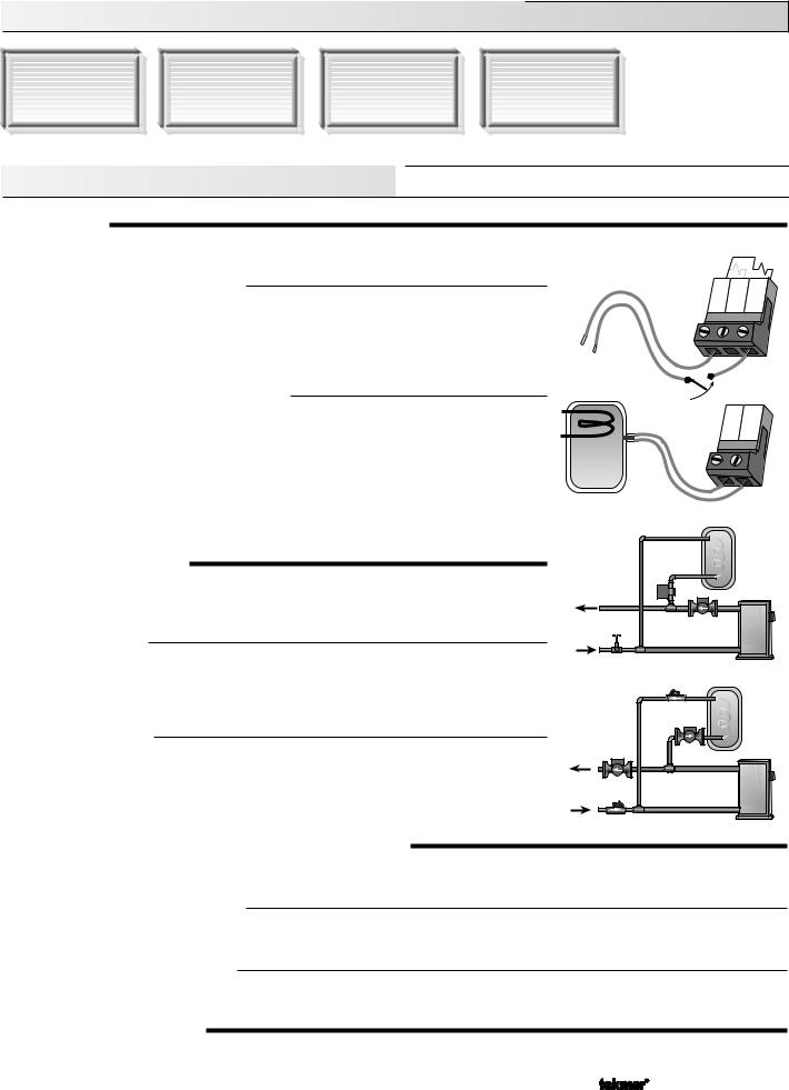
External Demand (10K 2 = NONE)
The 363 registers an external demand for DHW when a voltage between 24 and 240 V (ac) is applied across the Setp/DHW and the Com Dem terminals (5 and 3). Either a DHW aquastat or setpoint control is used as a switch in the DHW demand circuit. Once the 363 detects a DHW demand, the DHW Demand pointer turns on in the LCD and the control operates as described below.
Internal Demand Sensor (10K 2 = DHW)
If the 10K 2 setting is selected as DHW, the 363 looks for a DHW sensor connected to the 10K 2 and the Com Sen terminals (18 and 17). The DHW TANK setting is used to set the desired indirect DHW tank temperature.
When the temperature at the DHW sensor drops 3˚F (1.5˚C) below the DHW TANK setting, the DHW Demand pointer turns on in the LCD and the control operates as described below. An advantage to using the DHW sensor is that the control can display the current DHW TANK temperature and record the highest and lowest DHW TANK temperatures. Also, the 363 can control the DHW temperature with more accuracy than when using an aquastat.
24 to 240 V (ac)
DHW
Storage Tank
3 |
4 |
5 |
Com |
Boil Setp/ |
|
Dem Dem DHW |
||
Aquastat
17 |
18 |
Com 10K |
|
|
2 |
DHW DEVICE (DHW THRU)
Once the 363 has received a DHW demand, the sequence of operation depends on the type of DHW device selected. The DHW device is selected using the DHW THRU item in the Adjust menu.
DHW Valve (VALV)
If VALV is selected as the DHW device and there is a DHW demand, the 363 closes the DHW Pmp / Vlv contact (9 and 10) and the Boil P1 contact (7 and 8). The boiler pump provides flow through the DHW tank’s heat exchanger once the DHW valve is opened. The 363 operates the boiler to provide a sufficient boiler supply temperature to the DHW tank.
DHW Pump (PUMP)
If PUMP is selected as the DHW device, the 363 assumes that the DHW pump provides adequate flow through both the DHW tank heat exchanger and the boiler. To provide heat to the DHW tank, the 363 closes the DHW Pmp / Vlv contact (9 and 10) and operates the boiler to provide a sufficient Boil SUP temperature to the DHW tank. If using a primary loop with the DHW tank piped in primary / secondary, select DHW VALV.
Valve |
P |
Pump |
P |
BOILER TARGET DURING DHW GENERATION (Boil 0TRG)
The Boil TRG temperature during DHW operation depends on whether an external or internal demand is occurring. The DHW demand overrides the reset water temperature.
External Demand (10K 2 = NONE)
If the control receives a DHW demand through an external device such as an aquastat, the Boil TRG temperature is at least as hot as the DHW Heat Exchanger setting (DHW XCHG).
Internal Demand (10K 2 = DHW)
If the control receives a DHW demand from a DHW sensor attached to the 10K 2 and the Com Sen terminals (18 and 17), the Boil TRG temperature is at least as hot as the DHW TANK setting plus 40˚F (22˚C).
DHW DURING UNOCCUPIED
The DHW operation during an UnOccupied period depends on the type of DHW demand that the 363 is receiving and the type of setback that is being used. For this function to operate, the control must have the Setback / None DIP switch set to Setback.
9 of 40 |
Copyright © D 363 -12/08 |
External Demand (Aquastat)
If an external DHW Demand is used, the control can either continue operation of the DHW system as it would during the Occupied period or the control can ignore a call for DHW as long as the control is in an UnOccupied mode.
Internal Demand (Sensor)
If an internal DHW Demand is used, a DHW TANK Unocc temperature can be set. This is the temperature that the tank maintains as long as the control is in an UnOccupied mode.
Away
If the AWAY setting is made in the Schd menu, any DHW Demand is ignored and the tank cools off. Note: AWAY does not require the DIP switch = Setback.
Section C2 —DHW Priority
DHW PRIORITY
It is often desirable to limit or even stop the flow of heat to the heating system when the DHW tank calls for heat. This allows faster recovery of the DHW tank. The 363 has a number of features that it can use when dealing with DHW priority. The features available depend on the type of DHW device that is being used and the type of DHW Demand the control receives.
MixingPriority(DHW PRI= MIX)
It can be selected that the DHW tank has priority over the mixing zones. If this option is chosen, the mixing device is throttled back on a call for DHW. The Mix P2 pump continues to operate based on the Mix Demand. By reducing the mixing device output, more heat is directed to the DHW tank. The boiler zones continue to operate without change. This setting is available if DHW THRU is set to PUMP or VALV.
Boiler and Mixing Priority (DHW PRI = B+M)
It can be selected that the DHW tank has priority over the boiler and mixing zones. If this option is chosen, the mixing device is throttled back and the boiler pump (P1) turns off on a call for DHW. This setting is available only if a pump is selected as the DHW device (DHW THRU set to PUMP). Ensure that the flow rate of the DHW pump is adequate for both the DHW heat exchanger and the boiler.
P2 |
P |
P1 |
P2 |
P |
DHW |
P1 |
DHW PRIORITY OVERRIDE
To prevent the building from cooling off too much or the possibility of a potential freeze up during DHW priority, the 363 limits the amount of time for DHW priority. As the outdoor air temperature becomes colder, the length of time that the 363 provides DHW priority is reduced. Once the allowed time for priority has elapsed, the 363 overrides the DHW priority and operates DHW and heating simultaneously.
CONDITIONAL DHW PRIORITY
If the boiler supply temperature is maintained at or above the required temperature during DHW generation, this indicates that the boiler has enough capacity for DHW and possibly heating as well. As long as the boiler supply temperature is maintained near its target, DHW and heating occurs simultaneously.
DHW POST PURGE
After the DHW Demand is removed, the 363 performs a purge on the boiler. The 363 shuts off the boiler and continues to operate either the DHW pump or the DHW valve and the boiler pump. This purges the residual heat from the boiler into the DHW tank. The 363 continues this purge for a maximum of four minutes or until the boiler supply temperature drops 20˚F (11˚C) below the DHW Boil TRG temperature. The 363 also stops the purge if the boiler supply temperature drops below the current Boil TRG temperature.
DHW MIXING PURGE
After DHW operation, the boiler is extremely hot. At the same time, the heating zones may have cooled off considerably after being off for a period of time. To avoid thermally shocking the boiler after DHW priority, the 363 shuts off the boiler, but continues to operate the DHW while restarting the heating system. This allows some of the DHW return water to mix with the cool return water from the zones and temper the boiler return water.
Increasing Time |
DHW priority demand time limit |
Increasing Air Temperature
Outdoor air temperature
P |
P |
Copyright © D 363 -12/08 |
10 of 40 |
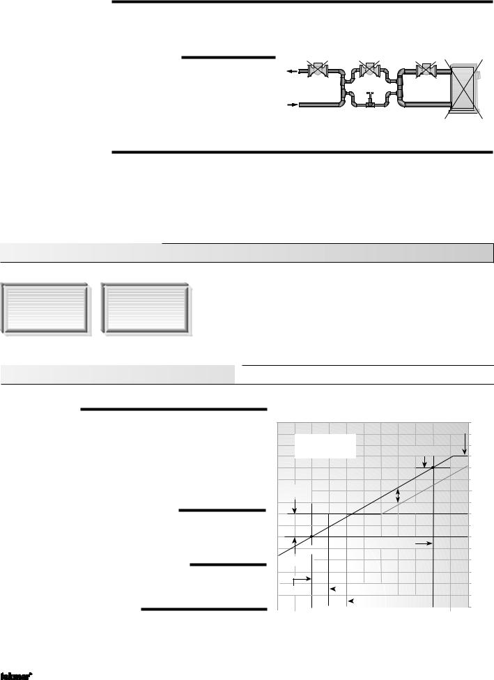
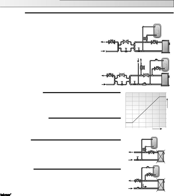
Section C3 —DHW with Low Temperature Boilers (without Mixing)
If DHW is to be incorporated into a low temperature system such as a radiant heating system, a mixing device is often installed to isolate the high DHW supply temperature from the lower system supply temperature. If a mixing device is not installed, high temperature water could be supplied to the low temperature system while trying to satisfy the DHW demand. This may result in damage to the low temperature heating system. The 363 is capable of providing DHW in such a system while ensuring that the low temperature in the heating system does not exceed its allowed maximum setting.
To prevent high temperature water from being introduced into the heating system, the Boiler Pump (P1) must be turned off during a call for DHW. To do this, DHW THRU must be set to PUMP, DHW PRI must be set to B + M, and Boil MIN must be set to OFF.
On a call for DHW, the 363 provides DHW priority by shutting off the Boiler Pump (P1) for a period of time. This time is based on the outdoor air temperature as described in the DHW Priority Override section. If the DHW Demand is not satisfied within the allotted time, the boiler shuts off and the boiler’s heat is purged into the DHW tank.
Once the boiler supply temperature is sufficiently reduced, the DHW pump shuts off. Then the heating system is turned on for a period of time to prevent the building from cooling off. After a period of heating, if the DHW demand is still present, the 363 shuts off the heating system and provides heat to the DHW tank once again.
P |
DHW |
P1 |
For correct operation, close attention must be paid to the mechanical layout of the system. When the 363 turns off the Boiler Pump (P1), flow to the heating system must stop. If flow is not stopped, the temperature in the heating system can exceed the maximum desired temperature and can result in damage to the heating system.
Section C4 —Setpoint
The 363 can handle setpoint loads which are high temperature loads connected to the boiler loop that are not heating loads or DHW. For this feature to be available, either a DHW sensor must be used or the DHW THRU item is set to NONE. If an external DHW demand is used as described in Section C1, you cannot use the setpoint feature.
SETPOINT DEMAND
The 363 registers a Setpoint Demand when a voltage between 24 and 240 V (ac) is applied |
|
across the Setp / DHW and the Com Dem terminals (5 and 3). Once voltage is applied, the |
|
setpoint demand pointer turns on in the LCD. The control operates the boiler to maintain at |
|
least the boiler supply temperature as set by the SETPOINT Occ setting. The Setpoint Demand |
|
does not turn on the Boiler Pump (P1). If a setpoint load is used, the installer must make sure |
|
that the setpoint device provides its own flow through the boiler. |
24 to 240 V (ac) |
3 |
4 |
5 |
Com Boil Setp/ |
||
Dem DemDHW |
||
BOILER TARGET DURING SETPOINT (Boil TRG)
The Boil TRG temperature during a Setpoint Demand is increased to at least the SETPOINT setting. This temperature is maintained as long as the 363 has a Setpoint Demand.
SETPOINT SETBACK (SETPOINT UnOcc)
If the 363 is placed into setback, the Setpoint Dem is ignored if the SETPOINT UnOcc setting is set to OFF. Otherwise, the setpoint operates normally. If a system override of AWAY is selected, the 363 operates the SETPOINT load at the Occupied setting.
SETPOINT PRIORITY (SETP PRI = B+M)
For setpoint loads to have priority over the Boiler and Mixing zones, set SETP PRI to B + M. If this option is chosen, the output from the mixing device is suspended and the Boiler Pump (P1) turns off during a Setpoint Demand.
Priority Override
In order to prevent the building from cooling off too much or the possibility of a potential freeze up during setpoint priority, the 363 limits the amount of time for setpoint priority. As the outdoor air temperature becomes colder, the length of time the 363 provides setpoint priority is reduced. Once the allowed time for priority has elapsed, the 363 overrides the setpoint priority and operates setpoint and heating simultaneously.
Conditional Setpoint Priority
If the Boil SUP temperature is maintained at or above the required temperature during setpoint generation, this indicates that the boiler has enough capacity for setpoint and possibly heating as well. As long as the Boil TRG temperature is maintained, setpoint and heating occur at the same time.
11 of 40 |
Copyright © D 363 -12/08 |

Section D —Mixing Reset


Section D1 |
Section D2 |
Section D3 |
General Mixing |
Mixing Device |
Alternate Mixing |
Operation |
|
Demands |
Section D1—General Mixing Operation
MIXING DEMAND
A mixing demand is generated by applying a voltage between 24 and 240 V (ac) across the Mix Demand terminals (1 and 2). Once voltage is applied, the Mix Demand pointer is displayed in the LCD. If the 363 is not in WWSD, the 363 closes the Mix P2 contact and the Boil P1 contact. The control turns on the boiler pump and mixing pump segments in the LCD. The 363 calculates a MIX TRG supply temperature based on the outdoor air temperature and settings. If required, the 363 operates the boiler in order to provide heat to the mixing device.
MIXING START (MIX STRT) (RESET RATIO)
The MIX STRT temperature is the mixing supply water temperature that the heating system requires when the outdoor air temperature equals the OUT STRT air temperature.
OUTDOOR START (OUT STRT) (RESET RATIO)
The OUT STRT temperature is the outdoor air temperature at which the control provides the MIX STRT supply water temperature to the system.
OUTDOOR DESIGN (OUT DSGN)
(RESET RATIO & CHARACTERIZED HEATING CURVE)
The OUT DSGN is the outdoor air temperature that is the typical coldest temperature of the year where the building is located. This temperature is used when doing heat loss calculations for the building.
MIX DESIGN (MIX DSGN)
(RESET RATIO & CHARACTERIZED HEATING CURVE)
The MIX DSGN temperature is the supply water temperature required to heat the mixing zones when the outdoor air is as cold as the Outdoor Design temperature.
|
|
|
|
1 |
2 |
|
|
|
|
|
|
|
Mix |
|
|
|
|
|
|
|
|
Demand |
|
|
|
|
24 to 240 V (ac) |
|
|
|
|
|
|
||
Mixing Reset |
|
|
|
|
210 |
|
||
|
|
MIX MAX |
(99) |
|
||||
|
Ratio |
|
|
|
|
|
190 |
|
|
|
|
|
MIX DSGN |
|
(88) |
|
|
|
|
|
|
|
|
|
||
|
|
|
|
|
|
|
170 |
Temperature |
|
|
|
|
|
|
|
(77) |
|
|
|
|
|
|
|
|
150 |
|
|
|
|
|
|
k |
|
(66) |
|
|
|
|
|
|
|
|
|
|
|
|
|
l |
c |
|
|
Water |
|
|
|
|
a |
|
|
|
||
|
|
|
a |
tb |
|
|
130 |
|
|
|
|
rm |
e |
|
|
||
|
|
|
o |
S |
|
|
(54) |
|
|
|
|
N |
|
|
|
||
|
|
|
MIX SETB |
|
|
110 |
Supply |
|
|
|
|
|
|
|
|
||
MIX STRT |
|
|
|
|
|
(43) |
||
|
|
|
|
|
|
|
||
|
|
|
|
|
|
|
90 |
|
|
|
|
OUT DSGN |
|
|
(32 |
|
|
|
|
WWSD Occ |
|
|
|
70 |
|
|
|
|
|
|
|
|
|
|
|
OUT STRT |
|
|
WWSD Unocc |
|
|
(21) |
|
|
80 |
60 |
40 |
20 |
|
0 |
-20 |
|
|
(27) |
(16) |
(5) |
(-7) |
(-18) |
(-29) |
|
||
Outdoor Air Temperature
MIXING MAXIMUM (MIX MAX)
(RESET RATIO & CHARACTERIZED HEATING CURVE)
The MIX MAX sets the highest water temperature that the control is allowed to calculate as the MIX TRG temperature. If the control does target the MIX MAX setting, and the MIX SUP temperature is within 5˚F (3˚C) of the MIX MAX, the Maximum pointer is displayed in the LCD while either the MIX TRG temperature or the MIX SUP temperature is being viewed.
Mixe |
|
|
|
|
|
d |
|
|
|
|
|
S |
|
|
|
|
|
u |
|
|
|
|
|
p |
|
|
|
|
|
p |
|
|
|
|
|
l |
|
|
|
|
|
y |
|
|
|
|
e |
W |
|
|
|
|
r |
a |
|
|
|
|
|
|
|
|
u |
||
t |
|
|
|
t |
|
e |
|
|
a |
|
|
|
|
r |
|
|
|
r |
|
e |
|
|
|
p |
|
|
|
||
|
Tem |
|
|
|
|
Pointer On |
|
|
|
|
Pointer On |
Mix MAX
WARM WEATHER SHUT DOWN (WWSD) OCC & UNOCC
(RESET RATIO & CHARACTERIZED HEATING CURVE )
When the outdoor air temperature rises above the WWSD setting, the 363 turns on the WWSD pointer in the display. When the control is in Warm Weather Shut Down, the Mix Demand pointer is displayed if there is a demand. However, the control does not operate the heating system to satisfy this demand. The control does respond to either a DHW Demand or a Setpoint Demand and operates as described in Section C.
Copyright © D 363 -12/08 |
12 of 40 |
Loading...