


256
- Installation & Operation Manual
D 256
Boiler Control 256
07/11
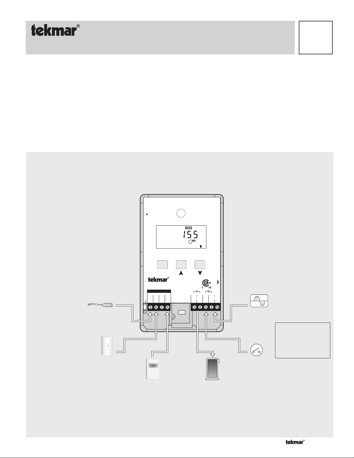
The Boiler Control 256 is designed to control a single stage heat source in order to provide outdoor reset. The control has a Liquid
Crystal Display (LCD) to view system status and operating information.
Additional functions include:
• Quick Setup for easy installation and programming of control
• User comfort adjustment to increase or decrease building space
temperature
• Advanced settings to fi ne-tune building requirements
Press & Release:
all 3 buttons, to adjust menu
Press & Hold:
Item, to view settings
, to test.
tektra 909-01
BOIL
• Test sequence to ensure proper boiler operation
• Setback input for energy savings
• CSA C US certifi ed (approved to applicable UL standards)
Power: 24 V ±10% 50/60 Hz
3 VA Class 2
Relay: 240 V (ac) 5 A 1/6 hp
Meets Class B:
Canadian ICES
FCC Part 15
H1190D
F
Input
Universal Sensor
Included
Input
Outdoor Sensor
Included
Terminal Unit Boiler Demand
Item
Boiler Control 256
One Stage Boiler
Do not apply power
1
Boil2Out3Com4UnO
Inst / Adv
Input
tekmar Timer
Optional
Sw
TIME
1
PRGM
AMPM
2
UNOCC
OVR
S
SMWTFT
OCC
Designed &
Assembled in
Canada
Signal wiring
must be rated
at least 300V
5
Boiler
67T8
Output
Boiler
Power
R+
Date Code
9
C-
Input
24 V (ac)
Power Supply
Input
Boiler Demand
Signal
Note:
Boiler demand must have
an electrical closure
between terminals 7
and 9 before the boiler
is able to fire.
1 of 20 © 2011 D 256 - 07/11
How to Use the Data Brochure
This brochure is organized into four main sections. They are: 1) Sequence of Operation, 2) Installation, 3) Control Settings, and 4)
Troubleshooting. The Sequence of Operation section has three sub-sections. We recommend reading Section A: General Operation
of the Sequence of Operation, as this contains important information on the overall operation of the control. Then read the sub-sections that apply to your installation. For quick installation and setup of the control, refer to the Installation section, DIP Switch Setting
section, followed by the Quick Setup section.
The Control Settings section (starting at DIP Switch Setting) of this brochure, describes the various items that are adjusted and displayed
by the control. The control functions of each adjustable item are described in the Sequence of Operation.
Table of Contents
User Interface ..................................................... pg 2
Description of Display Elements ....................... pg 3
Sequence of Operation ...................................... pg 4
Section A: General Operation ................ pg 4
Section B: Boiler Reset ......................... pg 5
Installation........................................................... pg 8
DIP Switch Setting .............................................pg 15
Quick Setup ........................................................pg 15
Reference Material: Essay E 003 “Characterized Heating Curve and Reset Ratio”
Control Settings .................................................pg 16
View Menu ...............................................pg 16
Adjust Menu ............................................pg 16
Testing and Troubleshooting............................pg 18
Error Messages .......................................pg 19
Technical Data ...................................................pg 19
Limited Warranty .............................................. pg 20
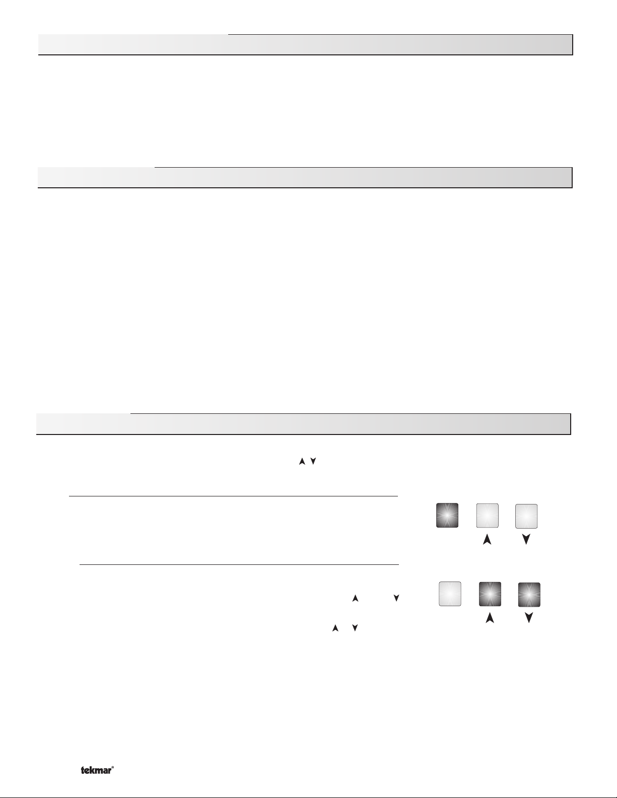
User Interface
The 256 uses a Liquid Crystal Display (LCD) as the method of supplying information. You use the LCD in order to set up and monitor the
operation of your system. The 256 has three push buttons (Item, , ) for selecting, viewing, and adjusting settings. As you program
your control, record your settings in the ADJUST menu table which is found in the second half of this brochure.
Item
The abbreviated name of the selected item will be displayed in the item fi eld of the
display. To view the next available item, press and release the Item button. Once you
have reached the last available item, pressing and releasing the Item button will return
the display to the fi rst item.
Item
Adjust
To make an adjustment to a setting in the control, press and hold simultaneously for
1 second, all 3 buttons. The display will then show the word ADJUST in the top right
corner. Then select the desired item using the Item button. Finally, use the and / or
button to make the adjustment.
To exit the ADJUST menu, either select the ESC item and press the
leave the adjustment buttons alone for 20 seconds.
When the Item button is pressed and held in the VIEW menu, the display scrolls through all the control adjust items in both access
levels.
Additional information can be gained by observing the status fi eld and pointers of the LCD. The status fi eld will indicate which of the
control’s outputs are currently active. Most symbols in the status fi eld are only visible when the VIEW menu is selected.
© 2011 D 256 - 07/11 2 of 20
or button, or
Item
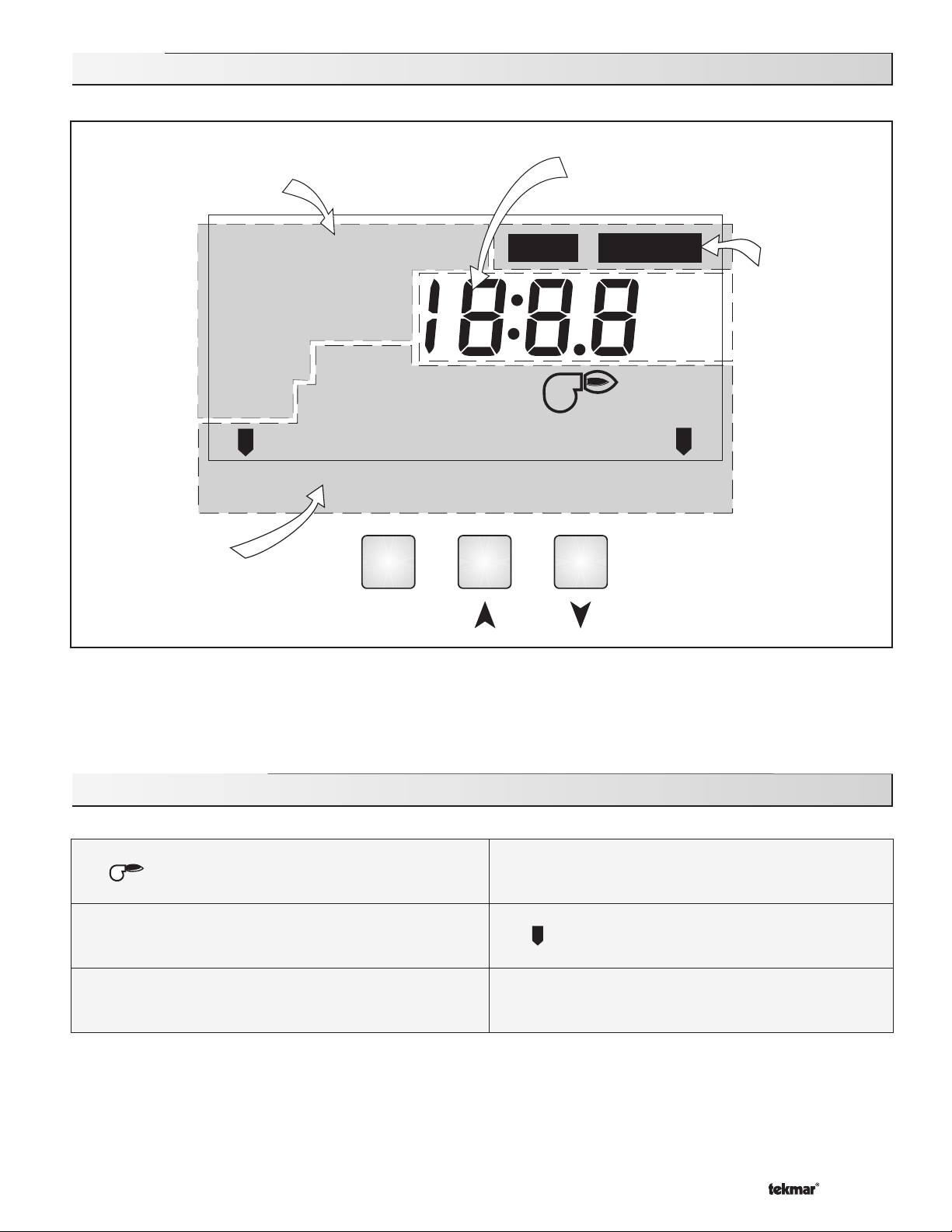
Display
Item Field
Displays an
abbreviated name of
the selected item
OUTDR
BOIL
ROOM WWSD
INDR
Terminal Unit
Status Field
Displays the current
status of the control’s
inputs, outputs and
operation
DSGN
TARGET
MAXMIN
UN
OCC
Item
DIFF
Number Field
Displays the current value
of the selected item
VIEW ADJUST
F
°
C
°
Boiler Demand
Buttons
Selects Menus, Items and
{
adjusts settings
Menu Field
Displays the
current menu
Symbol Description
Burner
Displays when the boiler relay is turned on.
OCC
UNOCC
3 of 20 © 2011 D 256 - 07/11
Occupied Schedule
Displays when the control is in occupied (Day)
mode.
Unoccupied Schedule
Displays when the control is in unoccupied
(Night) mode.
F, °C
°
°F, °C
Displays the unit of measure that all of the
temperatures are to be displayed in the control.
Pointer
Displays the control operation as indicated by
the text.
Sequence of Operation
Section A
General Operation
Page 4
Section B
Boiler Reset
Page 5-8
Section A — General Operation
POWERING UP THE CONTROL
When the Boiler Control 256 is powered up, the control displays the
control type number in the LCD for 2 seconds. Next, the software version
is displayed for 2 seconds. Finally, the control enters into the normal
operating mode, and the LCD defaults to displaying the current outdoor
air temperature.
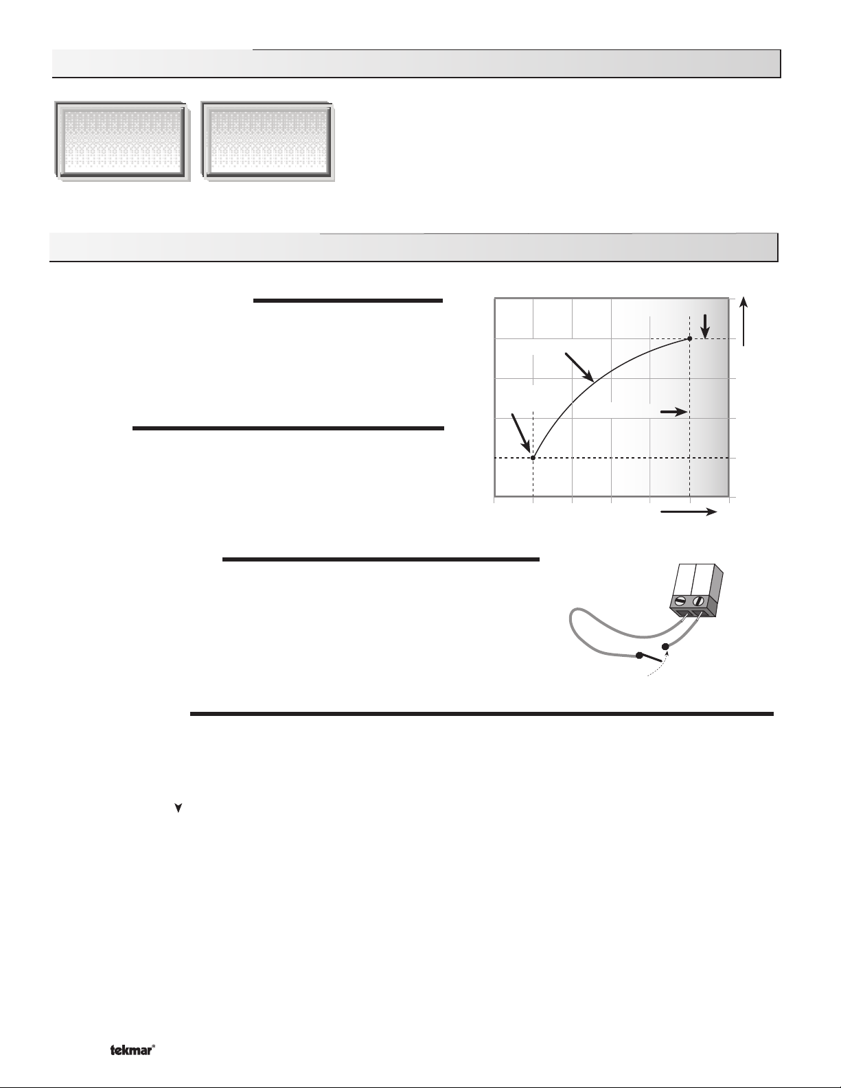
OPERATION
The 256 operates a single on / off heat source to control the supply
water temperature to a hydronic system. The supply water temperature
is based on the current outdoor air temperature and the Characterized
Heating Curve settings.
Terminal Unit
Indoor Design
Decreasing Outdoor Temperature
Outdoor Design
Design Supply
Increasing Water Temperature
SETBACK (UNOCCUPIED)
To provide greater energy savings, the 256 has a setback capability. With setback, the supply
water temperature in the system is reduced when the building is unoccupied. By reducing
the supply water temperature, air temperature in the space may be reduced even when
thermostat(s) are not turned down. Any time the Com (3) and the UnO Sw (4) terminals
are shorted together, the control operates in the unoccupied (Night) mode. When in the
unoccupied (Night) mode, the UNOCC segment is displayed in the LCD. The 256 adjusts
the supply water temperature based on the UNOCC settings made in the control.
FACTORY DEFAULTS
The control comes preset with several factory defaults. These defaults are based on the terminal unit selection (see section B2). To
fi ne-tune building requirements, these defaults may be changed. If a factory default value for a terminal unit is changed, the terminal
unit number will fl ash when selected in the ADJUST menu.
To reload the factory defaults listed in section B2, power down the control and wait for 10 seconds. Power up the control while simultaneously
holding the Item and buttons. The terminal unit number should now be displayed constantly in the LCD rather than fl ashing.
4
3
Com
UnO
Sw
Timer switch
© 2011 D 256 - 07/11 4 of 20
Section B: Boiler Reset
Section B1
General
Section B2
Installer
Section B3
Advanced
Section B1: General
7
8
9
Power
R+
C-
T
BOILER DEMAND
A boiler demand is required in order for the 256 to provide heat to the heating system. A
boiler demand is generated by connecting terminal T(7) to terminal C-(9) through a switching
device. Once the switching device closes, the Boiler Demand pointer is displayed in the
LCD. The 256 calculates a BOIL TARGET supply temperature based on the outdoor air
temperature and settings.
BOILER OPERATION
When the 256 determines that boiler operation is required, the Boiler contact terminals (5 and 6) close. While the Boiler contact is
closed, the burner segment in the LCD is displayed.
24 V (ac)
Boiler demand switches
CHARACTERIZED HEATING CURVE
The 256 varies the supply water temperature based on the outdoor air temperature. The control takes into account the type of terminal
unit that the system is using. Since different types of terminal units transfer heat to a space using different proportions of radiation,
convection and conduction, the supply water temperature must be controlled differently. Once the control is told what type of terminal
unit is used, the control varies the supply water temperature according to the type of terminal unit. This improves the control of the
air temperature in the building.
BOILER TARGET TEMPERATURE (BOIL TARGET)
The BOIL TARGET temperature is determined from the Characterized Heating Curve settings and the outdoor air temperature. The
control displays the temperature that it is currently trying to maintain as the boiler supply temperature. If the control does not presently
have a requirement for heat, it does not show a boiler target temperature. Instead, “- - -” is displayed in the LCD. At no time does the
control operate the boiler above 248°F (120°C).
Section B2: Installer
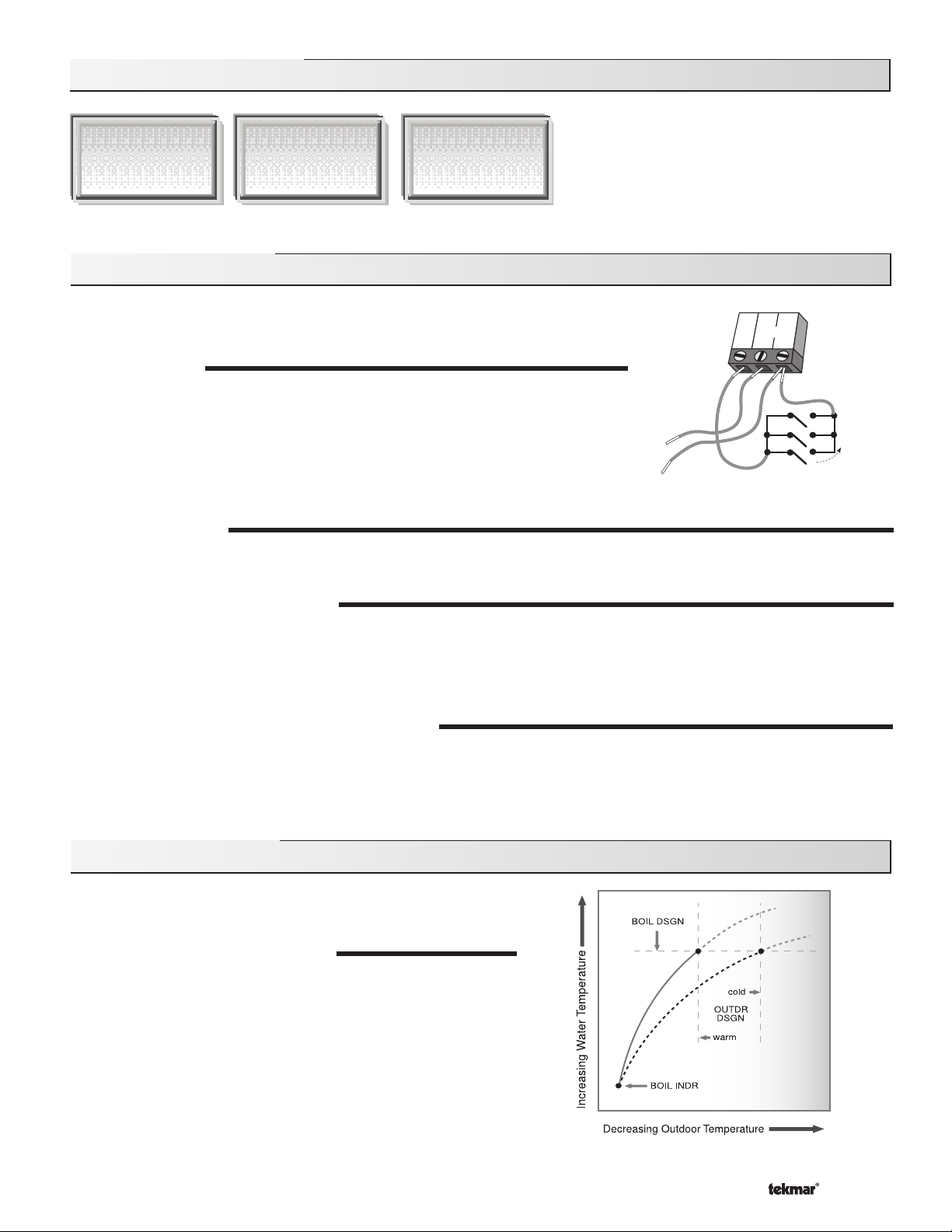
OUTDOOR DESIGN (OUTDR DSGN)
The OUTDR DSGN is the outdoor air temperature that is the typical
coldest temperature of the year where the building is located. This
temperature is used when doing the heat loss calculations for the
building. If a cold outdoor design temperature is selected, the boiler
supply temperature rises gradually as the outdoor temperature drops.
If a warm outdoor design temperature is selected, the boiler supply
temperature rises rapidly as the outdoor temperature drops.
5 of 20 © 2011 D 256 - 07/11
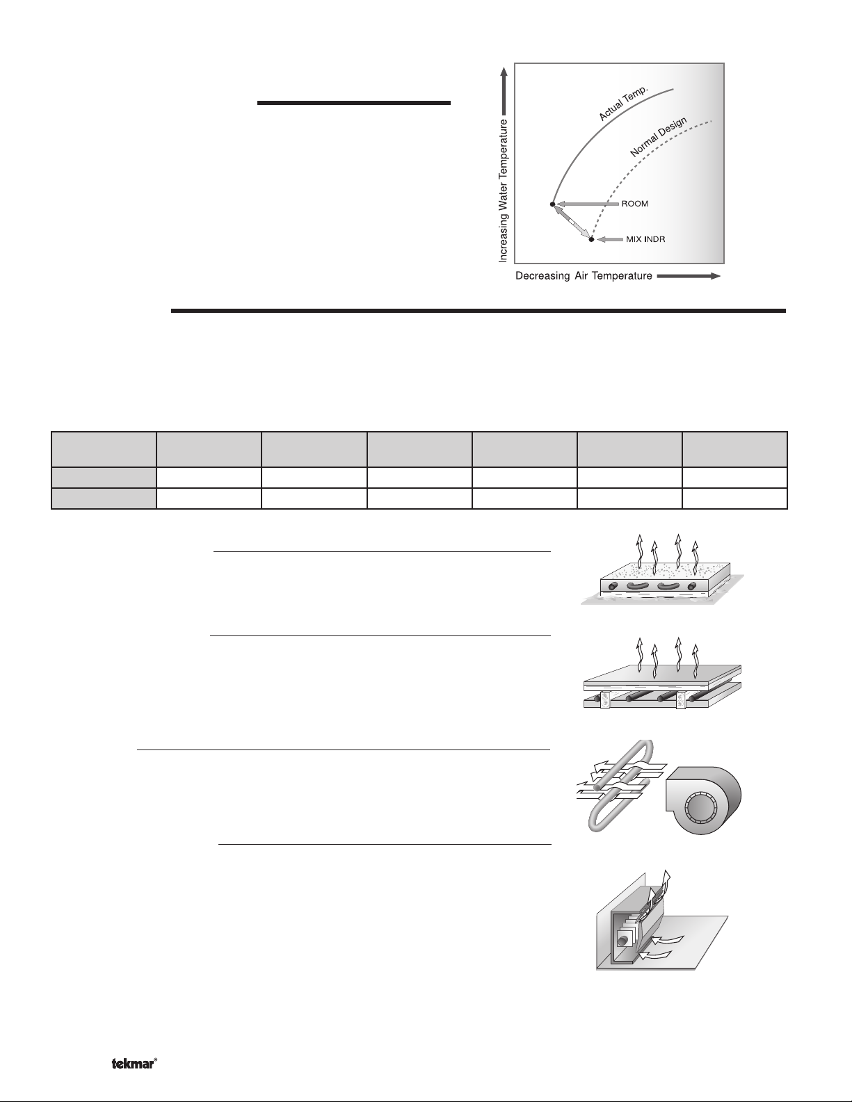
ROOM OCC & UNOCC (ROOM)
The ROOM is the desired room temperature for the boiler zones, and it
provides a parallel shift of the Characterized Heating Curve. The room
temperature desired by the occupants is often different from the design
indoor temperature (BOIL INDR). If the room temperature is not correct,
adjusting the ROOM setting increases or decreases the amount of
heat available to the building. A ROOM setting is available for both the
occupied (Day) and unoccupied (Night) modes.
TERMINAL UNITS
When using a Characterized Heating Curve, the control requires the selection of a terminal unit. The terminal unit determines the shape
of the Characterized Heating Curve according to how the terminal unit delivers heat into the building space (refer to Essay E 003). The
256 provides for selection between six different terminal unit types: two types of radiant fl oor heat, fancoil, fi n-tube convector, radiator
and baseboard. When a terminal unit is selected, the control automatically loads the design supply temperature (BOIL DSGN) and
minimum supply temperature (BOIL MIN). The factory defaults are listed below. To change defaults, refer to section B3. If a default
has been changed, refer to section A to reload the factory defaults.
Terminal Unit
BOIL DSGN 120°F (49°C) 140°F (60°C) 190°F (88°C) 180°F (82°C) 160°F (71°C) 150°F (66°C)
BOIL MIN OFF OFF 140°F (60°C) 140°F(60°C) 140°F (60°C) 140°F (60°C)
High Mass Radiant (1)
This type of a hydronic radiant fl oor is embedded in either a thick concrete or gypsum
pour. This heating system has a large thermal mass and is slow acting.
Default values: BOIL DSGN = 120°F (49°C), BOIL MIN = OFF
Low Mass Radiant (2)
This type of radiant heating system is either attached to the bottom of a wood sub-fl oor,
suspended in the joist space, or sandwiched between the sub-fl oor and the surface.
This type of radiant system has a relatively low thermal mass and responds faster than
a high mass system.
Default values: BOIL DSGN = 140°F (60°C), BOIL MIN = OFF
High Mass Radiant
(1)
Low Mass Radiant
(2)
Fancoil
(3)
Fin-tube Convector
(4)
Radiator
(5)
Baseboard
(6)
Fancoil (3)
A fancoil terminal unit or air handling unit (AHU) consists of a hydronic heating coil and
either a fan or blower. Air is forced across the coil at a constant velocity by the fan or
blower, and is then delivered into the building space.
Default values: BOIL DSGN = 190°F (88°C), BOIL MIN = 140°F (60°C)
Fin–tube Convector (4)
A convector terminal unit is made up of a heating element with fi ns on it. This type of
terminal unit relies on the natural convection of air across the heating element to deliver
heated air into the space. The amount of natural convection to the space is dependant
on the supply water temperature to the heating element and the room air temperature.
Default values: BOIL DSGN = 180°F (82°C), BOIL MIN = 140°F (60°C)
© 2011 D 256 - 07/11 6 of 20
 Loading...