


- Data Brochure |
D 662 |
Snow Detector & Melting Control 662 |
07/99 |
|
OUTSIDE |
Power |
|
|
F C |
Remote |
|
|
|
WWCO |
CWCO |
|
|
Melting |
Idling |
|
|
Water |
Maximum |
Supply |
Target ∆T |
∆T |
|
Return |
Actual ∆T |
Maximum |
Minimum |
Slab |
% Output |
Supply |
Return |
Boiler Return |
|
To change between |
|
Pump 1 |
Pump 2 |
°F and °C, press and |
|
||
hold for 1 sec. |
|
Opening |
Closing |
Item |
|
Boiler |
|
|
|
|
|
|
|
Warning |
|
Snow Detector & Melting Control 662 |
|
LR 58223 |
|
|
|
|
|
Mixing Operation |
N |
R LT / C |
|
The tekmar Snow Detector & Melting Control 662 is a microprocessor-based control which, together with the Snow/Ice Sensor 090, activates and controls the rate of heat delivery to a snow melt system. This versatile control has three modulating outputs to control the heat delivery for most pump and/or valve arrangements. Protection of both the snow melt slab and the boiler is achieved through several safety features. Faster pick up times are also ensured through a viscosity compensation function which optimizes the rate of heat delivery to the slab during start up. The 662 combines all the necessary features to make snow melting safe and trouble free.
|
|
|
|
|
Sequence of Operation |
|
|
pg. 2 |
|
Testing . . . . . . . . . . . . . |
pg. 9 |
||||||||||||||||||
|
|
|
|
|
Installation . . . . . . . . . . |
|
|
pg. 3 |
|
Error Messages . . . . . . |
pg. 10 |
||||||||||||||||||
|
|
|
|
|
Settings . . . . . . . . . . . . |
|
|
pg. 7 |
|
Technical Data . . . . . . . |
pg. 12 |
||||||||||||||||||
|
|
|
|
|
Display Operation . . . . |
|
|
pg. 8 |
|
Limited Warranty . . . . . |
pg. 12 |
||||||||||||||||||
Relative Energy |
Water is detected |
|
|
Slab is warm enough, |
|
|
|
120 Vac power |
|
|
Weather is too cold, |
|
Control is limiting heat |
|
|||||||||||||||
usage in ∆T x Hours |
by the sensor |
|
no snow melting is required |
|
|
supply is on |
|
|
|
snow melting is off |
|
output to Max ∆T setting |
|
||||||||||||||||
Boiler return |
Current % Heat |
|
|
Snow detected: |
|
Remote Enable |
|
Control is limiting supply |
|
Control is in |
|
Control is maintaining |
|||||||||||||||||
temperature |
Output to slab |
|
|
control is in |
|
|
Signal present |
|
|
temperature to Max. |
|
|
Idling mode |
|
Min. boiler return temperature |
||||||||||||||
|
|
|
|
|
Melting mode |
|
|
|
|
|
|
|
|
|
Supply setting |
|
|
|
|
|
|
|
|
|
|||||
|
|
|
|
|
|
|
|
|
|
|
|
|
|
|
|
|
|
|
|
|
|
|
|
|
|
|
|
Desired slab surface |
|
|
|
|
|
|
|
|
|
|
|
|
|
|
|
|
|
|
|
|
|
|
|
|
|
|
|
|
|
temperature during |
|
Target slab ∆T |
|
|
|
|
|
|
|
|
|
|
|
|
|
|
|
|
|
|
|
|
|
|
|
|
|
|
|
melting mode |
|
Actual slab ∆T |
|
|
|
|
|
|
|
|
|
|
|
|
|
|
|
|
|
|
Power |
|
120 V ac 50/60 Hz 300 VA |
|
|
|
Desired slab surface |
||||
|
|
|
|
|
|
|
|
|
|
|
|
|
|
|
|
|
|
System Pumps |
120 V ac 6 A 1/3 hp, pilot duty 240 VA 2 A |
|
temperature during |
||||||||
|
|
|
|
|
|
|
|
|
|
|
|
|
|
|
|
|
|
|
Variable Pump |
120 V ac 50/60 Hz 2.2 A 1/6 hp, internally fused |
|||||||||
Supply temperature to slab |
|
|
|
|
|
|
|
|
|
|
|
|
|
|
Power |
|
|
Mix Relays |
24 V ac 10 A, pilot duty 48 VA 2 A |
|
idling mode |
||||||||
|
|
|
|
|
|
|
|
OUTSIDE |
|
|
|
|
|
|
Other Relays |
120 V ac 10 A 1/3 hp, pilot duty 240 VA 2 A |
|
|
|||||||||||
|
|
|
|
|
|
|
|
|
|
|
|
|
|
|
|
|
Enclosed |
Energy |
Management Equipment |
|
|
Sensor Sensitivity to |
|||||||
Slab surface temperature |
|
|
|
|
|
|
|
|
|
|
|
|
|
|
|
|
|
|
|
|
|||||||||
|
|
|
|
|
|
|
|
|
F C |
|
|
|
|
Remote |
|
|
Manufactured |
|
|
|
2094 |
Date |
|||||||
|
|
|
|
|
|
|
|
|
|
|
|
|
|
|
|
|
|
water |
|
||||||||||
|
|
|
|
|
|
|
|
|
|
|
|
|
|
|
|
|
|
|
1234567 |
S/N |
|
||||||||
Boiler pump is on |
|
|
|
|
|
|
|
|
|
|
|
|
|
WWCO |
|
CWCO |
in Canada by |
|
|
|
|
||||||||
|
|
|
|
|
|
|
|
|
|
|
|
|
|
|
|
39°F |
|
|
29°F |
|
50 % |
|
Test button to initiate |
||||||
System pump is on |
|
|
|
|
|
|
|
|
|
|
|
|
|
|
|
|
|
|
|
|
|
|
|
||||||
|
|
|
|
|
|
|
|
|
|
|
|
|
|
Melting |
|
Idling |
|
|
|
|
|
|
|
|
|
test sequence |
|||
Valve is |
|
|
Slab |
|
|
|
|
|
|
% Output |
|
|
|
Water |
|
Maximum |
|
|
|
|
|
|
|
|
Maximum Supply |
||||
|
|
|
|
|
|
|
|
|
|
|
|
∆T |
|
|
|
|
24 |
|
|
|
|
||||||||
opening/closing |
|
|
Supply |
|
|
|
|
Usage (∆T x hrs) |
|
|
|
Maximum |
Minimum |
34 |
|
44 |
Off |
35 |
20 |
|
80 |
temperature |
|||||||
|
|
|
Actual ∆T |
|
|
|
|
|
Boiler Return |
|
|
|
Supply |
|
Return |
|
Melting |
Surface |
Idling |
Sensitivity |
Min. Boiler Return |
||||||||
LCD display |
|
|
Target ∆T |
|
|
|
|
|
|
|
|
|
|
|
|
|
|
|
|
|
|
||||||||
|
|
|
|
|
|
|
|
|
|
|
|
|
|
|
|
|
|
|
150°F |
|
100°F |
|
|||||||
item select |
|
|
|
|
|
|
|
To change between |
|
|
|
Pump 1 |
|
Pump 2 |
|
|
|
|
|
|
|
|
|
temperature |
|||||
|
|
|
|
|
|
|
|
°F and °C, press and |
|
|
|
|
|
|
|
|
|
|
|
|
|
|
|
||||||
Boiler operating |
|
|
|
|
|
|
|
hold for 1 sec. |
|
|
|
|
Opening |
Closing |
|
|
|
|
|
60 |
|
|
Max. Temperature |
||||||
|
|
|
|
|
Item |
|
|
|
|
|
|
|
|
|
|
|
|
|
|
||||||||||
|
|
|
|
|
|
|
|
|
|
|
|
|
|
|
|
|
|
Test |
|
100 |
200 |
Off |
150 |
drop across slab |
|||||
Fault warning |
|
|
|
|
|
|
|
|
|
|
|
|
|
|
Boiler |
|
|
|
|
||||||||||
|
|
|
|
|
|
|
|
|
|
|
|
|
|
|
|
|
|
|
|
Max. Supply Min. Boil Return |
|
|
|||||||
|
|
|
|
|
|
|
|
|
|
|
|
|
|
|
|
|
|
|
|
|
|
|
Cold Weather Cut-off |
||||||
|
The Snow/Ice Sensor is installed in a hostile environment. |
|
|
|
|
Warning |
|
|
30°F |
|
|
0°F |
|
130 sec |
|
||||||||||||||
Output: |
It should be cleaned and checked on a regular basis. |
|
|
|
|
|
|
|
|
|
|
|
|
|
|
|
|
|
|
temperature |
|||||||||
|
|
|
|
|
|
|
|
|
|
|
|
|
|
|
|
|
|
|
|
|
|
|
|
|
|
|
|
|
|
Melt relay is closed |
Snow Detector & Melting Control 662 |
|
|
|
R |
LR 58223 |
|
|
|
|
|
-20 |
|
|
|
tekmar |
Motor Speed setting |
||||||||||||
when control is |
|
|
|
|
|
|
|
|
|
|
|
|
|
motor |
|||||||||||||||
|
|
|
|
|
|
|
10 |
|
|
50 |
Off |
25 |
30 |
|
230 |
|
|
||||||||||||
in melting mode. |
Floating / Variable Speed / 4-20 mA |
|
|
|
|
|
|
N R T L / C |
|
|
|
|
|
|
Terminal Plugs |
||||||||||||||
|
|
|
|
|
|
|
|
|
|
|
|
|
|
|
|
|
∆T Max. |
CWCO |
Motor Speed / |
||||||||||
|
|
|
|
|
|
|
|
|
|
|
|
|
|
|
|
|
|
|
|
||||||||||
|
Use Nº 20 AWG or larger copper conductors rated for at least 75°C / 300V |
1000Ω |
|
|
|
|
|
|
|
|
|
Pump Response |
|
|
|||||||||||||||
|
|
|
|
|
Do not apply power here |
|
|
|
|
|
|||||||||||||||||||
Warning relay is |
1 |
2 |
3 |
4 |
5 |
6 |
7 |
8 |
9 |
10 |
11 |
12 13 14 |
15 |
16 17 |
18 19 20 21 22 23 24 25 26 27 28 29 |
H11002 |
|
|
|||||||||||
Melt |
Warning |
N |
L |
Pmp |
Pmp |
Pmp Pmp |
Boiler |
+ |
– |
Mix |
Mix |
Mix |
Sen Sen |
Sen |
Sen |
Sen Sen En |
Sen Sen Sen |
Sen |
Sen |
|
|
||||||||
Output: |
|
|
|
|
Power |
Com |
P1 |
P2 |
Var |
|
|
4-20 4-20 Com |
Opn |
Cls |
Red Blk |
Blu |
Yel |
Brn Com Rem |
Bret Com Ret |
Sup |
Out |
|
|
|
|||||
activated if sensor |
|
|
|
|
|
|
|
|
|
|
|
|
|
|
|
|
|
|
|
|
|
|
|
|
|
|
|
|
|
fault is detected |
|
|
|
|
|
|
|
|
|
|
|
|
|
|
|
|
|
|
|
|
|
|
|
|
|
|
|
Input: Outdoor |
|
|
|
|
|
|
|
|
|
|
|
|
|
|
|
|
|
|
|
|
|
|
|
|
|
|
|
|
|
Sensor 070 |
|
|
|
|
|
|
|
|
|
|
|
|
|
|
|
|
|
|
|
|
|
|
|
|
|
|
|
|
|
(Included) |
|
|
|
|
|
|
|
|
|
|
|
|
|
|
|
|
|
|
|
|
|
|
|
|
|
|
|
|
|
Input: System Supply |
|
|
|
|
|
|
|
|
|
|
|
|
|
|
|
|
|
|
|
|
|
|
|
|
|
|
|
|
|
Sensor 071(Included) |
|
Output: Turn on |
|
|
|
|
|
|
|
|
|
|
|
|
|
|
|
|
|
|
|
|
|
|
|
|
|
|
|
|
|
system pump P1 |
|
|
|
|
|
|
|
|
|
|
|
|
|
|
|
|
|
|
|
|
|
|
|
|
|
|
|
Input: System Return |
|
|
|
|
|
|
|
|
|
|
|
|
|
|
|
|
|
|
|
|
|
|
|
|
|
|
|
|
|
||
|
|
|
|
|
|
|
|
|
|
|
|
|
|
|
|
|
|
|
|
|
|
|
|
|
|
|
|
Sensor 071(Included) |
|
|
|
|
|
Input: Boiler Return |
|
Output: Turn on |
|
|
|
Sensor 071(Included) |
|
boiler pump P2 |
|
|
|
|
|
120 Vac |
|
OR |
|
Input: Remote Enable |
|
Power Supply |
|
|
Signal. (Optional) |
||
|
|
M |
M |
OR |
|
|
|
|
|
||
|
|
|
|
Input: Slab Sensor 072 (Included) |
|
Output: |
|
|
|
Detects slab temperature |
|
|
|
|
only. Does not detect Snow/Ice. |
||
operate pump at |
|
|
|
||
Output: |
Output: control |
Output: control |
Input: Snow/Ice Sensor 090 installed with Sensor Socket 091. (Optional) |
||
varying speeds |
|||||
|
Turn on boiler |
4-20 mA device |
Floating Action |
Both of these components must be ordered separately. |
In order for this control to operate effectively, it must be installed in a well designed melting system. The Application Brochures A 662 provide a series of schematics which can be used with this control. Any deviations from these drawings must be discussed with a tekmar factory representative to ensure that system performance is not compromised. The application drawings are not final designs - each component within the system must be correctly sized for the control to operate effectively. It is important that the sequence of operation and the application drawings for this control are fully understood to ensure that the control selected is compatible with its intended use.
Sequence of Operation


Powering up the control
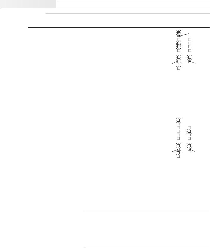
After the Snow Detector & Melting Control 662 is powered up, the red status lights and the LCD segments are turned on for 7 seconds. The control then displays the “Outdoor” temperature.
Melting Mode
Operation using a Snow/ Ice Sensor 090 - The control continually monitors the Snow/Ice Sensor 090. When water is detected, the “Water” light turns on and if the control is not in WWCO or CWCO (see page 3 for an explanation of these terms), melting mode begins.
Operation using a Remote Enable - Melting mode can also be initiated if a remote enable signal is present (terminals Com Sen and Rem Sen shorted together) and the control is not in WWCO or CWCO. The remote enable is typically used with multiple Snow Melting Controls and Snow/ Ice Sensors. It can be also be used to manually turn the melting system on by wiring a switch between the remote terminals. A remote enable switch must be installed when a Slab Sensor 072 is used as this sensor cannot detect water.
Opening light is on if the melting system requires more heat
If a remote signal is Power present, the Remote
light turns on
Remote
|
WWCO |
|
CWCO |
|
Melting |
|
Idling |
|
|
||
|
Water |
|
Maximum |
|
|
∆T |
|
|
Maximum |
|
|
|
|
Minimum |
|
|
Supply |
|
Return |
|
|
||
|
Pump 1 |
|
Pump 2 |
|
|
||
|
Opening |
|
Closing |
|
|
|
Boiler |
Closing light is on |
|
if the melting |
|
|
Warning |
system requires |
|
less heat |
Once the control is in melting mode, the Melting relay and boiler pump (relay P2 Pmp) are turned
on. After a 4 second delay, the system pump (relay P1 Pmp) is turned on and after 8 seconds, heat is applied to the snow melt system through either a variable speed pump, a floating action mixing valve or a 4-20 mA device. The opening and closing lights indicate whether the control is increasing or decreasing the heat applied to the snow melt system. Essay E 021 compares the use of these devices for controlling the system temperature and also discusses the sizing and operation of the variable speed pump. Information on floating action can be found in Essay E 000. The 4-20 mA, variable speed pump and mixing valve outputs operate simultaneously. The 4-20 mA output can therefore be used to provide a remote readout of the pump or valve operation. The control remains in melting mode until no water is detected for at least 30 seconds and the slab is up to temperature for at least 30 minutes. Cold Weather or Warm Weather Cut Off can also terminate melting mode. When the control exits melting mode the boiler and system pumps are operated for an additional 90 seconds to purge the boiler. If the control switches from melting to idling mode, the boiler is not purged.
Idling Mode |
|
|
|
|
|
|
|
|
|
|
|
||
When the melting system starts off from a cold temperature, the time required for the slab to reach |
|
Power |
|
|||
|
|
|||||
|
|
|
|
|||
“Melting” temperature can be excessive. To decrease this start up time, the slab can be maintained |
|
Remote |
|
|||
at an “Idling” temperature until melting is required. The idling feature is also useful for preventing |
|
WWCO |
|
CWCO |
||
|
|
|||||
|
Melting |
|
Idling |
|||
frost and light ice formation. When the control is in idling mode, control operation is similar to melting |
|
|
||||
|
Water |
|
Maximum |
|||
mode except the “Melting” and “Water” lights are off and the “Idling” light is on. |
|
|
∆T |
|||
|
Maximum |
|
||||
|
|
Minimum |
||||
|
|
|||||
|
|
|
|
Supply |
|
Return |
|
|
Opening light is |
|
Pump 1 |
|
Pump 2 |
|
|
|
|
|||
|
|
on if the melting |
|
Opening |
|
Closing |
|
|
system requires |
|
|
||
|
|
more heat |
|
Boiler |
Closing light is on |
|
|
|
|
|
if the melting |
||
|
|
|
|
Warning |
system requires |
|
Snow melt system protection features |
|
|
less heat |
|||
|
|
|
|
|
||
|
|
|
|
|
||
The 662 control has several features for protection of the snow melt system: |
|
|
|
|
||
-to protect the slab from cracking due to thermal stresses, the control limits the rate of heat applied to the slab through a “∆T Max” setting. The ∆T represents the difference between the slab supply and return fluid temperatures which are measured by the control. If this temperature difference approaches the “∆T Max” setting, the “Maximum ∆T” light turns on and the control operates the valve or pump to maintain the ∆T at the “∆T Max” setting.
-to protect the piping and other components in the system, the control limits the supply temperature to a “Max. Supply” setting. When the melt system supply temperature approaches the maximum supply setting, the “Maximum Supply” light turns on and the control operates the valve or pump to reduce the supply temperature.
-to prevent the flue gases in the boiler from condensing, the control limits the boiler return temperature to a “Min. Boil. Return” setting. When the boiler return temperature approaches this setting, the “Minimum Return” light turns on and the control operates the valve or pump to increase the boiler return temperature.
∆T compensation for changes in fluid viscosity
Glycol solutions used in snow melt systems have widely varying viscosities between high and low temperatures. As the glycol solution temperature drops, viscosity increases causing a reduction in flow rate. This reduction in flow rate reduces the rate of heat output if the fluid temperature drop across the slab (∆T) remains constant. To compensate for this, the control increases the Maximum ∆T. This compensation is only applied when the fluid temperature is below 30°F, which is the temperature at which the viscosity of a typical 40% ethylene glycol / 60% water solution starts to increase significantly. The compensation feature is designed for fluids containing 40% ethylene glycol or 30 % propylene glycol; however, if the glycol percentage in the solution is lower than these values, the quality of heat regulation is not significantly affected. When the control is compensating for viscosity changes, the “Maximum ∆T” light flashes.
Ramping the ∆T during melting system start up
When the control turns on the melting system, the “Target ∆T” is slowly ramped up to the maximum ∆T to prevent thermal shock of the slab. If the temperature of the fluid returning to the boiler (source) is sufficient, the ramping time is less than 17 minutes. If the heat source is not dedicated to snow melting and there are other heat demands on the source, the ramping time may be longer.
2
Warm Weather Cut Off (WWCO)
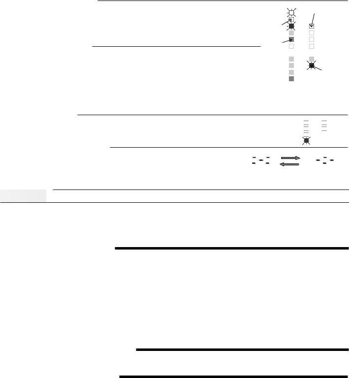
If the “Slab” and “Outdoor” temperatures rise above the “Melting” temperature, heating the slab is no longer required. The control therefore shuts down the melting system and enters WWCO. During WWCO the “Closing” light remains on continuously and the heat supplied through the valve or variable speed pump is reduced to zero. When the “Outdoor” or “Slab” temperature drops below the “Melting” temperature, the control exits WWCO and continues with normal operation.
Cold Weather Cut Off (CWCO)
|
|
|
Note: |
|
Power |
|
In Cold Weather Cut |
|
|
Off, the CWCO light is |
|
|
|
|
on and the WWCO |
|
Remote |
|
light is off |
|
|
|
|
|
|
|
|
|
|
|
|
|
|
|
|
|
|
|
|
|
|
|
|
|
|
|
|
|
|
|
|
Maintaining the slab at a “Melting” or “Idling” temperature in extremely cold weather can be expensive and may even be impossible. When it does snow at these colder temperatures, the snow
is usually dry, light and less slippery. The control therefore turns the melting system off when the “Outdoor” temperature drops below the “CWCO” setting. During CWCO the “Closing” light remains
on continuously and the heat supplied through the valve or pump is reduced to zero. The heater
in the Snow/ Ice Sensor 090 is kept on during CWCO until the control detects snow. If snow is detected, the heater is turned off but the control retains the snow detected information. When the outdoor temperature rises above the “CWCO” temperature, the control exits CWCO and if the Snow/Ice Sensor 090 detected snow during CWCO, the control initiates melting mode.
Warning Light and Relay
If a sensor fault occurs, the Warning relay and light are turned on and an error message is given. The look-up table provided on pages 10 and 11 can be used to determine which sensor has the fault.

 Pump 1
 Pump 2

 Opening
 Closing

 Boiler
Warning
Exercising of the Pumps and Valves
To prevent the pumps or valves from seizing after long inactive periods, the pumps and valves are operated after every 3 days of no operation. The Pump P1 and Pump P2 relays are turned on for 20 seconds and the mixing valve or variable speed pump output is run fully open and/or fully closed. During exercising, the LCD screen alternates between two special characters as illustrated in the diagram.
|
|
|
|
|
|
|
|
|
|
|
|
|
|
|
|
|
|
|
|
|
|
|
|
|
|
|
|
|
|
Slab |
|
|
|
|
|
|
|
|
|
|
|
|
% Output |
Slab |
|
|
|
|
|
|
|
|
|
|
|
|
% Output |
||
|
|
|
|
|
|
|
|
|
|
|
|
|
|
|
|
|
|||||||||||||
Supply |
|
|
|
|
|
|
|
|
Usage (∆T x hrs) |
Supply |
|
|
|
|
|
|
|
|
|
Usage (∆T x hrs) |
|||||||||
Actual ∆T |
|
|
|
|
|
|
|
|
|
Boiler Return |
Actual ∆T |
|
|
|
|
|
|
|
|
|
|
Boiler Return |
|||||||
|
|
|
|
|
|
|
|
|
|
|
|
|
|
|
|
|
|||||||||||||
Target ∆T |
|
|
|
|
|
|
|
|
|
|
|
|
Target ∆T |
|
|
|
|
|
|
|
|
|
|
|
|
||||
Installation


Caution
Improper installation and operation of this control could result in damage to equipment and possibly even personal injury. It is your responsibility to ensure that this control is safely installed according to all applicable codes and standards. This electronic control is not intended for use as a primary limit control. Other controls that are intended and certified as safety limits must be placed into the control circuit.
Step One |
|
Getting ready |
|
||
|
Check the contents of this package. If any of the contents listed are missing or damaged, please refer to the Limited Warranty and Product Return Procedure on the back of this brochure and contact your wholesaler or tekmar sales agent for assistance.
Type 662 includes: • One Snow Detector & Melting control 662 • One Outdoor Sensor 070
•Three Universal Sensors 071 • One Slab Sensor 072
•One Data Brochure D 662 • Application Brochures A 662 • One Data Brochure D 001
Other information available: • Essay E 021 • Essay E 000 • Essay E 600
Read Brochures A 662 and select the correct Application for your job.
Note: This control can be installed with EITHER a Snow/Ice Sensor 090 and Sensor Socket 091 OR a Slab Sensor 072. The Snow/Ice Sensor 090 and Sensor Socket 091 are not included with the type 662 and must be ordered separately.
Carefully read the details of the Sequence of Operation sections in all applicable brochures to ensure that you have chosen the proper control and understand its functions within the operational requirements of your system.
Step Two |
|
Mounting of the base |
|
||
|
The control should be removed from its base by pressing down on the release clip in the wiring chamber and sliding upwards on the control. The base is then mounted in accordance with the instructions in the Data Brochure D 001.
Step Three |
|
Rough-in Wiring |
|
||
|
All electrical wiring terminates in the control base wiring chamber. It has standard 7/8" (22mm) knock-outs that accept all common wiring hardware and conduit fittings. Before breaking out the knock-outs, check the wiring diagram and select those sections of the chamber with common voltages. Do not allow the wiring to cross over sections as safety dividers, installed later, prevent this.
Power should not be applied to any of the wires during the rough-in wiring stage.
•EITHER: Install the Snow/Ice Sensor 090 according to the instructions in Data Brochure D 090 and run the wiring back to the base. See Data Brochure 090 for very important details on sensor location and installation.
•OR: Install the Slab Sensor 072 according to the instructions in the Data Brochure D 001 and run the wiring back to the base.
See page 5 for very important details on sensor location and installation.
•Run the wiring from the other system components to the base.
•Run 120 V ac to the power terminals on the control. Use a clean 120 V ac power source to ensure proper operation.
•Multi-strand 16 AWG wire is recommended for the 120 V ac wiring due to its superior flexibility and ease of installation into the terminal.
3

Step Four |
|
|
|
|
|
|
Electrical connections to the control |
|
|
|
|
|
|
|
|
|
|
|
|
|
|
|
|
|
||||
|
|
|
|
|
|
|
|
|
|
|
|
|
|
|
|
|
|
|
|
|
|
|||||||
|
|
|
|
|
|
|
|
|
|
|
|
|
|
|
|
|
|
|
|
|
|
|||||||
Power and output connections |
|
|
|
|
|
|
|
|
|
|
|
|
|
|
|
|
|
|||||||||||
|
|
|
|
|
|
|
|
|
|
|
|
|
|
|
|
|
||||||||||||
• |
The installer should test to confirm no voltage is present at any of the wires. |
|
|
5 |
6 |
7 |
|
|
8 |
9 |
|
10 |
|
|
||||||||||||||
• |
Install the control back into the base by sliding it down until it snaps in firmly. |
|
|
Power |
Com |
|
P1 |
|
P2 |
|
Var |
|
|
|||||||||||||||
• |
Connect the 120 V ac power supply to terminals Power N — L (5 and 6). |
|
|
N |
L |
|
Pmp |
|
Pmp |
|
Pmp |
Pmp |
|
|
||||||||||||||
Melt Output |
|
|
|
|
|
|
|
|
|
|
|
|
|
|
|
|
|
|
|
|
|
|
|
|
||||
|
|
|
|
|
|
|
|
|
|
|
|
|
|
|
|
|
|
|
|
|
|
|
|
|||||
• |
Connect the melting device to terminals Melt (1 and 2). These terminals lead to an unpowered |
|
|
|
|
1 |
|
2 |
3 |
|
4 |
|
|
|||||||||||||||
|
(dry) relay contact inside the control which closes when the control enters melting mode. The |
|
|
|
|
|
|
|
|
|
|
|
|
|
|
|
|
|||||||||||
|
|
|
|
|
|
Melt |
|
Warning |
|
|
||||||||||||||||||
|
most common devices to be enabled by the 662 are pumps, heating devices or other controls. |
|
|
|
|
|
|
|
|
|||||||||||||||||||
Warning |
|
|
|
|
|
|
|
|
|
|
|
|
|
|
|
|
|
|
|
|
|
|
|
|
|
|
||
|
|
|
|
|
|
|
|
|
|
|
|
|
|
|
|
|
|
|
|
|
|
|
|
|||||
• |
If desired, connect a warning device to terminals Warning (3 and 4). These terminals lead to |
|
|
|
|
|
|
|
|
|
|
|
|
|
|
|
|
|||||||||||
|
a dry relay contact inside the control which closes when there is a sensor or wiring fault. |
|
|
|
|
1 |
|
2 |
3 |
|
4 |
|
|
|||||||||||||||
Caution: The 662 is an operating control and is not certified as a safety device. If safety |
|
|
|
|
|
|
|
|
|
|
|
|
|
|
|
|
||||||||||||
|
|
|
|
|
Melt |
Warning |
|
|
||||||||||||||||||||
|
|
|
considerations are critical, a separate alarm system must be installed. |
|
|
|
|
|
|
|
||||||||||||||||||
|
|
|
|
|
|
|
|
|
|
|
|
|
|
|
|
|
|
|
||||||||||
Pump Power Supply |
|
|
|
|
|
|
|
|
|
|
|
|
|
|
|
|
|
|
|
|
||||||||
|
|
|
|
|
|
|
|
|
|
|
|
|
|
|
|
|
|
|
|
|||||||||
• |
Terminal Com Pmp (7) is the common power supply terminal for both terminals P1 Pmp (8) |
|
|
|
|
|
|
|
|
|
|
|
|
|
|
|
|
|||||||||||
|
and P2 Pmp (9). |
|
|
5 |
6 |
|
7 |
|
|
8 |
|
9 |
|
|
10 |
|
|
|||||||||||
• |
If the pumps P1 and P2 are operated from the same 120 V ac power supply as the control, |
|
|
Po |
wer |
|
Com |
P1 |
|
P2 |
|
Var |
|
|||||||||||||||
|
connect the terminal Power L (6) to the terminal Com Pmp (7). |
|
|
N |
L |
|
Pmp |
Pmp |
Pmp |
Pmp |
|
|||||||||||||||||
• If a separate power supply is required for P1 and/or P2, contact tekmar for details. |
|
|
|
|
|
|
|
|
|
|
|
|
|
|
|
|
||||||||||||
System Pump P1 |
|
|
|
|
|
|
|
|
|
|
|
|
|
|
|
|
|
|
|
|
|
|||||||
|
|
|
|
|
|
|
|
|
|
|
|
|
|
|
|
|
|
|
|
|
||||||||
|
|
|
|
|
|
|
|
|
|
|
|
|
|
|
5 |
6 |
|
7 |
|
|
|
|
9 |
|
|
10 |
|
|
• |
Connect the System Pump to terminals Power N — P1 Pmp (5 and 8). These terminals lead |
|
|
|
|
|
8 |
|
|
|
|
|
||||||||||||||||
|
|
Po |
wer |
|
Com |
|
P1 |
|
P2 |
|
Var |
|
||||||||||||||||
|
to a dry relay contact which closes when the control requires System Pump operation. |
|
|
|
|
|
|
|
||||||||||||||||||||
Boiler Pump P2 |
|
|
|
|
|
|
|
|
N |
L |
|
Pmp |
|
Pmp |
|
Pmp |
|
Pmp |
|
|||||||||
|
|
|
|
|
|
|
|
|
|
|
|
|
|
|
|
|
|
|
|
|
|
|||||||
|
|
|
|
|
|
|
|
|
|
|
|
|
|
|
|
|
|
|
|
|
||||||||
• |
Connect the Boiler Pump to terminals Power N — P2 Pmp (5 and 9). These terminals lead |
|
5 |
6 |
7 |
|
|
8 |
|
9 |
|
10 |
|
|
||||||||||||||
|
|
Po |
wer |
|
Com |
|
P1 |
|
P2 |
|
Var |
|
||||||||||||||||
|
to a dry relay contact which closes when the control requires Boiler Pump operation. |
|
|
|
|
|
|
|
||||||||||||||||||||
Variable Speed |
|
|
|
|
|
|
|
|
|
N |
L |
|
Pmp |
|
Pmp |
|
Pmp |
|
Pmp |
|
||||||||
|
|
|
|
|
|
|
|
|
|
|
|
|
|
|
|
|
|
|
|
|
|
|
||||||
|
|
|
|
|
|
|
|
|
|
|
|
|
|
|
|
|
|
|
|
|
||||||||
• Connect the variable speed pump to terminals Power N —Var Pmp (5 and 10). Pumps |
|
|
|
|
|
|
|
|
|
|
|
|
|
|
|
|
||||||||||||
|
|
5 |
6 |
|
7 |
|
|
8 |
9 |
|
|
10 |
|
|
||||||||||||||
|
operated by this circuit must be permanent capacitor, impedance protected with a locked rotor |
|
|
|
|
|
|
|
|
|||||||||||||||||||
|
|
|
Po |
wer |
|
Com |
|
P1 |
|
P2 |
|
Var |
|
|
||||||||||||||
|
current less than 2.2 amps. The Snow Detector & Melting Control 662 has an internal 2.5 amp |
|
|
|
|
|
|
|
|
|||||||||||||||||||
|
|
|
N |
L |
|
Pmp |
|
Pmp |
Pmp |
|
Pmp |
|
|
|||||||||||||||
|
fuse for overload protection. This fuse is not field replaceable. Contact tekmar for details on |
|
|
|
|
|
|
|
||||||||||||||||||||
|
|
|
|
|
|
|
|
|
|
|
|
|
|
|
|
|
||||||||||||
|
return and repair procedures if this fuse is blown. |
|
|
|
|
|
|
|
|
|
|
|
|
|
|
|
|
|||||||||||
Boiler |
|
|
|
|
|
|
|
|
|
|
|
|
|
|
|
|
|
|
|
|
|
|
|
|
|
|
|
|
|
|
|
|
|
|
|
|
|
|
|
|
|
|
|
|
|
|
|
|
|
|
|
|
|
|
|
|
|
• |
Connect the boiler or the boiler control to the terminals Boiler (11 and 12). These terminals |
11 |
12 |
13 |
14 |
|
15 |
16 |
|
17 |
|
|
||||||||||||||||
|
lead to a dry relay contact which closes when the control requires boiler operation. |
|
|
|
4-20 |
|
|
4 - 20 |
Com |
Opn |
Cls |
|
|
|||||||||||||||
|
Boiler |
|
||||||||||||||||||||||||||
|
|
|
|
|
|
|
|
|
|
|
|
|
+ |
|
– |
|
|
Mix |
Mix |
Mix |
|
|
||||||
|
|
|
|
|
|
|
|
|
|
|
|
|
|
|
|
|
|
|
|
|
|
|
|
|
|
|
|
|
4-20 mA Device
•Connect the positive 4 - 20 mA lead to terminal 4-20 + (13) and the negative 4 - 20 mA lead to terminal 4 - 20 – (14). Maximum resistance allowed in the 4 - 20 mA circuit is 1000 Ω. The 4 - 20 mA output can be converted to a voltage output by connecting a resistor between terminals 13 and 14.
13 |
14 |
1 |
13 |
14 |
1 |
13 |
14 |
1 |
4-20 4-20 C |
4-20 4-20 C |
4-20 4-20 C |
||||||
+ |
– |
M |
+ |
– |
M |
+ |
– |
M |
|
|
|
|
|
500 Ω resistor |
|
|
66.5 Ω resistor |
|
|
|
|
|
4-20 mA converted |
|
|
|
|
|
|
|
|
to 2-10 Vdc output |
|
|
|
|
|
|
|
|
OR |
|
|
|
|
|
|
|
|
250 Ω resistor |
|
|
237 Ω resistor |
|
|
|
|
|
4-20 mA converted |
|
|
|
|
|
|
|
|
to 1-5 Vdc output |
|
|
|
+–
4 - 20 mA Actuating Motor
Connection to Operate a 4 - 20 mA Device
+–
1-5 or 2-10 Vdc Actuating Motor
Converting the 4 - 20 mA Output to Operate a 1 - 5 Vdc or 2 - 10 Vdc Device
W B R
0 - 135Ω "Slidewire"
Actuating Motor
Converting the 4 - 20 mA Output to Operate a 0 - 135Ω Actuating Motor
Floating Action Mixing Valve
•Connect one side (R) of a 24 V ac transformer to terminal Com Mix (15).
•Connect the (C) side of the transformer to terminal N/C on the tekmar 010 Actuating Motor.
For other makes of actuating motors, refer to the manufacturers' installation instructions.
•Connect the OPEN terminal of the Actuating Motor (CCW) to the terminal Opn Mix (16) on the control. This terminal leads to a relay contact which closes to provide 24 V ac to open the valve.
•Connect the CLOSE terminal of the Actuating Motor (CW) to the terminal Cls Mix (17) on the control. This terminal leads to a relay contact which closes to provide 24 V ac to close the valve.
11 |
12 |
13 |
14 |
15 |
16 |
17 |
|||
|
|
4-20 |
4-20 |
Com |
Opn |
Cls |
|||
Boiler |
+ |
|
– |
Mix |
Mix |
Mix |
|||
|
|
|
|
|
|
|
|
|
|
Separate Class II |
|
N |
1 |
2 |
|
|
Transformer |
|
C |
||
|
|
|
|
||
|
|
|
|
|
|
L |
24Vac |
R |
|
|
|
N |
|
C |
M |
type 010 |
|
4
 Loading...