


- Data Brochure |
D279 |
Steam Control 279 |
05/10 |
|
|
The tekmar Steam Control 279 can operate a single on-off steam boiler or an on-off steam valve using outdoor reset. The control determines the on time of the boiler or valve based on the measured outdoor temperature and settings entered by the installer. A large LCD displays the current status and operating temperatures.
Additional functions include: |
|
|
|
|
|
|
|
|
|
|
|
|
|
|
|
• CSA approved for use in USA and Canada |
|
|
|
|
|
|
• DHW Tankless Coil Operation |
||||||||
• Outdoor Reset |
|
|
|
|
|
|
|
• Warm Weather Shut Down |
|
||||||
• Manual Override |
|
|
|
|
|
|
|
• Built-in Programmable Timer |
|
||||||
• Includes Outdoor Sensor |
|
|
|
|
|
|
|
• 24 Hour, 5-1-1, 7 Day Schedule |
|||||||
• Includes Condensate Sensor |
|
|
|
|
|
|
• Two or Four Schedule Events Per Day |
||||||||
• Large LCD Display |
|
|
|
|
|
|
• Two Alert Level Relays |
|
|
||||||
• Optional Indoor Sensors |
|
|
|
|
|
|
|
|
|
|
|
|
|
|
|
|
|
|
|
|
|
|
|
Average |
|
|
Condensate Sensor |
||||
|
|
|
|
|
|
|
|
Indoor S2 |
|
|
DHW Tankless Coil Sensor |
||||
|
|
|
|
STATUS |
|
|
|
Indoor S1 |
|
|
Setback |
|
|
||
|
|
|
|
|
|
|
Installer |
|
|
|
|
|
|||
|
|
|
|
Establishing Steam |
User |
|
|
|
|
|
|||||
|
|
|
|
Heat Cycle |
|
|
|
|
O |
|
|
|
|
||
|
|
|
|
Lockout Differential |
|
|
|
|
|
|
|||||
|
|
|
|
|
|
|
|
Test |
|
||||||
|
|
|
|
DHW Tankless Coil Heating |
|
|
|
|
|||||||
|
|
|
|
|
|
|
|
|
|
|
|
|
o |
not testing |
|
|
|
|
|
|
|
|
|
|
|
|
|
|
red |
testing |
|
|
|
|
|
|
|
|
|
|
|
|
|
|
red |
testing paused |
|
|
|
|
|
|
|
|
|
|
|
|
|
|
For manual operation, |
||
|
|
|
|
|
|
|
|
|
|
|
|
|
press and hold Test |
||
|
|
|
|
|
|
|
|
|
|
|
|
|
button for 3 seconds. |
||
Menu Item |
|
|
|
|
|
|
|
|
|
|
|
|
|
|
|
|
|
|
|
|
|
|
|
Made in Canada By |
|
|
Meets Class B: |
||||
|
|
|
|
|
|
|
|
|
|
Canadian ICES |
|||||
|
|
|
|
|
|
|
|
tekmar Control Systems Ltd. |
|
FCC Part 15 |
|||||
|
|
|
|
|
|
|
|
tektra 969-04 |
|
|
|
|
|||
Steam Control 279 |
|
|
|
|
|
|
|
Power |
115 V ±10% 50/60 Hz 3.5 VA |
|
Code |
||||
|
|
|
|
|
|
|
Relays |
230 V (ac) 5 A 1/3 hp, pilot duty 240 VA |
|||||||
One Stage |
|
|
|
|
|
|
|
Signal wiring must be rated at least 300 V. |
|||||||
|
|
|
|
|
|
|
Date |
||||||||
|
|
|
|
|
|
|
|
||||||||
|
|
|
|
|
|
|
|
|
Do not apply power |
|
|||||
|
|
|
|
|
|
|
|
|
|
|
|||||
1 |
2 |
3 |
4 |
5 |
6 |
7 |
8 |
9 |
10 |
11 12 13 |
14 15 16 |
H2046A |
|||
Power |
Alert 1 |
Alert 2 |
Boiler |
Com Com DHW Indr |
Indr |
Com Cdn |
Out |
||||||||
|
|||||||||||||||
L |
N |
High |
Low |
|
|
Sen |
Sen |
Sen S2 |
S1 |
Sen Sen |
Sen |
|
|||
Input |
|
|
|
|
Input |
115 V (ac) |
|
|
|
|
Outdoor |
Power Supply |
|
|
|
|
Sensor |
|
|
|
|
|
Included |
Output |
|
|
|
|
Input |
High Priority |
|
|
|
|
Universal Sensor |
Alert |
|
|
|
|
Included |
|
OR |
M |
|
|
|
Output |
Output |
Input |
Input |
Input |
|
Low Priority |
Boiler or On /Off |
Universal Sensor |
Indoor Sensor |
Indoor Sensor |
|
Alert |
Steam Valve |
Optional |
Optional |
Optional |
|
|
|
1 of 24 |
|
© 2010 |
D 279 - 05/10 |

How to Use the Data Brochure
This brochure is organized into four main sections. They are: 1) Sequence of Operation, 2) Installation, 3) Control Settings, and 4) Testing and Troubleshooting. The Sequence of Operation section has fourteen sub-sections. We recommend reading ‘Section A: General’ of the Sequence of Operation, as this contains important information on the overall operation of the control. Then read the sub sections that apply to your installation.
The Control Settings section (starting at Switch Settings) of this brochure describes the various items that are adjusted and displayed by the control. The control functions of each adjustable item are described in the Sequence of Operation.
Table of Contents
User Interface ............................................................... |
2 |
Alert Relay Operation ........................................... |
9 |
Display and Symbol Description ................................... |
3 |
Domestic Hot Water Tankless Coil ..................... |
10 |
Definitions..................................................................... |
4 |
Installation .................................................................. |
10 |
Sequence of Operation................................................. |
4 |
Cleaning the Control................................................... |
14 |
General ................................................................. |
4 |
Switch Settings ........................................................... |
15 |
Establishing Steam ............................................... |
4 |
Display Menus ............................................................ |
16 |
Heating Cycle ....................................................... |
6 |
View Menu .......................................................... |
16 |
Lockout Differential ............................................... |
7 |
Adjust Menu........................................................ |
17 |
Optional Indoor Sensors....................................... |
8 |
Time Menu.......................................................... |
19 |
Built-in Timer ........................................................ |
8 |
Schedule Menu................................................... |
20 |
Programmable Schedule ...................................... |
8 |
Testing the Control...................................................... |
20 |
Warm Weather Shut Down ................................... |
8 |
Troubleshooting .......................................................... |
21 |
Optimum Start ...................................................... |
9 |
Error Messages .......................................................... |
22 |
Boost .................................................................... |
9 |
Technical Data ............................................................ |
24 |
Limited Occupied .................................................. |
9 |
Limited Warranty ........................................................ |
24 |
User Interface
The control uses a Liquid Crystal Display (LCD) as the method of supplying information. Use the LCD in order to setup and monitor the operation of the system. The control has four push buttons (Menu, Item, , ) for selecting and adjusting settings. As the control is programmed, record the settings in the ADJUST Menu table which is found in the second half of this brochure.
Menu
All of the items displayed by the control are organized into four menus: View, Adjust, Time, and Schedule. These menus are listed on the top of the display (Menu Field). To select a menu, use the Menu button. By pressing and releasing the Menu button, the display will advance to the next available menu. Once a menu is selected, there will be a group of items that can be viewed within the menu.
Note: The TIME and SCHEDULE menus are not available when Setback is turned off.
Menu Item
Item
The abbreviated name of the selected item will be displayed in the item field of the display. To view the next available item, press and release the Item button. Once you have reached the last available item in a menu, pressing and releasing the Item button will return the display to the first item in the selected menu.
The items can be quickly scrolled through by holding the Item button and then pressing the button. To rapidly scroll through the items in the reverse order, hold the Item button and press the
 button.
Menu Item
Adjust
To make an adjustment to a setting in the control, begin by selecting the appropriate menu using the Menu button. Then select the desired item using the Item button. Finally, use the  and /or
  button to make the adjustment.
Additional information can be gained by observing the Status field of the LCD. The status field will indicate which of the control’s outputs are currently active. Most symbols in the status field are only visible when the VIEW Menu is selected.
© 2010 |
D 279 - 05/10 |
Menu Item |
2 of 24 |
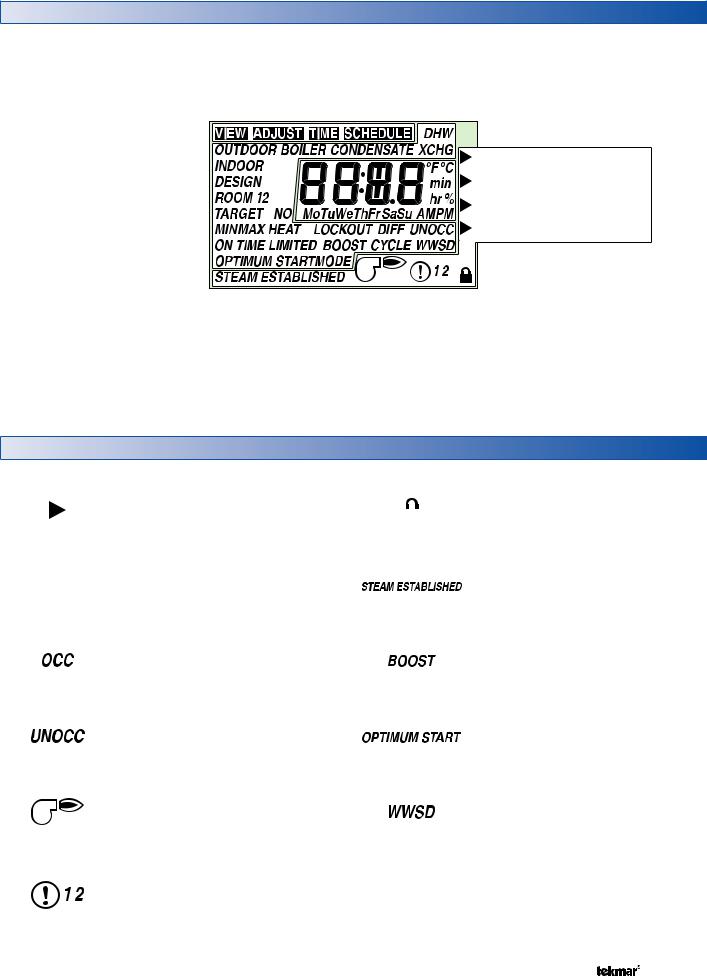
Display
Number Field |
Status Field |
Menu Field
Displays the current value |
Displays the current status of the |
of the selected item |
control’s inputs, outputs and operation |
Displays the |
STATUS |
|
current menu |
||
Establishing Steam |
||
|
||
|
Heat Cycle |
|
Item Field |
Lockout Differential |
|
Displays the current |
DHW Tankless Coil Heating |
|
item selected. |
||
|
Buttons
Selects Menus, Items
and adjusts settings
Menu Item
Symbol Description
|
POINTER |
|
|
USER ACCESS LEVEL |
|
|
|
Displays when the Installer / User |
|
|
Displays the control operation as |
|
|
|
|
|
|
Switch Setting is set to the User |
|
|
indicated by the text. |
|
|
|
|
|
|
access level. |
|
|
|
|
|
|
|
|
|
|
|
|
°F, °C |
|
|
STEAM ESTABLISHED |
°F°C |
|
|
Displays once the condensate sensor |
|
Units of measurement. |
|
|
reaches a temperature sufficient for |
|
|
|
|
||
|
|
|
|
steam to reach the furthest radiator. |
|
|
|
|
|
|
OCCUPIED SCHEDULE |
|
|
BOOST |
|
|
|
Displays while the boost feature |
|
|
Displays when the control is in the |
|
|
|
|
|
|
extends the boiler on time to allow |
|
|
Occupied event period. |
|
|
|
|
|
|
recovery after night setback. |
|
|
|
|
|
|
|
|
|
|
|
|
UNOCCUPIED SCHEDULE |
|
|
OPTIMUM START |
|
|
|
Displays while the Optimum Start |
|
|
Displays when the control is in the |
|
|
|
|
|
|
feature extends the boiler on time to |
|
|
Unoccupied event period. |
|
|
|
|
|
|
allow recovery after night setback. |
|
|
|
|
|
|
|
|
|
|
|
|
BURNER |
|
|
WWSD |
|
Displays when the boiler contact is |
|
|
Displays while the control is in Warm |
|
turned on. |
|
|
Weather Shut Down. |
|
|
|
|
|
|
WARNING 1 2 |
|
|
|
|
Displays when an error exists or |
|
|
|
|
when a limit has been reached. A |
|
|
|
|
1 indicates a high level alert, a 2 |
|
|
|
|
indicates a low level alert. |
|
|
|
|
|
|
|
|
3 of 24 |
© 2010 |
D 279 - 05/10 |

Definitions
The following defined terms and symbols are used throughout this manual to bring attention to the presence of hazards of various risk levels, or to important information concerning the life of the product.
Caution: Refer to accompanying documents.
Sequence of Operation
General |
|
|
|
|
|
|
|
|
|
Section A |
|
Powering up the control |
|
Status |
|
||||||||
|
|
|
|
|
|
|
|
|
|
|
|
When the control is powered on, all segments in the LCD |
The control has a status field on the right hand side of the |
||||||||||
are turned on for 2 seconds. Next, the control displays the |
control. A pointer is shown in the status field once the boiler |
||||||||||
control type number in the LCD for 2 seconds. Next, the |
contact is turned on. The pointer indicates at which point |
||||||||||
software version is displayed for 2 seconds. Last, the control |
of the steam heating system cycle the control is currently |
||||||||||
enters into the normal operating mode. |
operating at. |
|
|||||||||
Boiler Contact Operation |
The steps are as follows: |
|
|||||||||
• Establishing Steam |
|
||||||||||
|
|
|
|||||||||
In single on-off steam boiler applications, the control uses |
|
||||||||||
• Heat Cycle |
|
||||||||||
the boiler contact to connect to the thermostat terminals |
|
||||||||||
• Lockout Differential |
|
||||||||||
(T-T) on the boiler. The pressure control and all other safety |
|
||||||||||
• DHW Tankless Coil Heating |
|
||||||||||
devices and circuits must continue to be wired in series to |
|
||||||||||
|
|
|
|
|
|
|
|
|
|
||
the burner circuit. The boiler contact on the control is used |
|
|
|
|
|
|
|
|
|
STATUS |
|
|
|
|
|
|
|
|
|
|
|||
to turn on or off the steam boiler burner. |
|
|
|
|
|
|
|
|
|
Establishing Steam |
|
|
|
|
|
|
|
|
|
|
Heat Cycle |
||
In steam valve applications, the boiler contact on the control |
|
|
|
|
|
|
|
|
|
||
|
|
|
STATUS |
|
|
|
|
|
Lockout Differential |
||
|
|
|
|
|
|
|
|
||||
is used to power the valve motor to open the valve. When |
|
|
|
|
|
|
|
|
DHW Tankless Coil Heating |
||
|
|
|
|
|
|
|
|
|
|
|
|
power is removed, the valve must close. |
|
|
|
Establishing Steam |
|
|
|
||||
|
|
|
|
|
|
|
|
||||
|
|
|
|
||||||||
|
|
|
|
|
|
|
|
||||
|
|
Each of these steps are described in detail in the following |
|||||||||
|
|
sections. |
|
||||||||
Establishing Steam |
Section B |
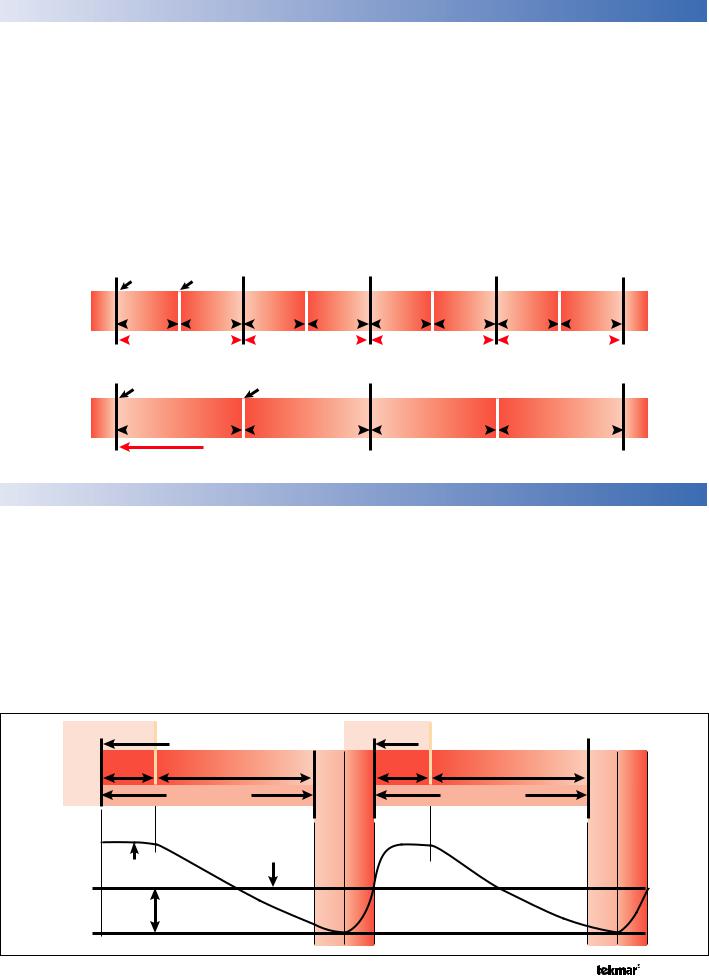
In steam heating systems, there is a time delay between when the steam boiler or steam valve is turned on and when the steam finally reaches the furthest radiator in the system. It is important for the control to determine how long this time delay is in order to ensure proper heating in all rooms. When heat is required, the control activates the boiler relay but does not consider the heating cycle to start until steam has been established at the furthest radiator. While the control is waiting to establish steam, the Status field will have a pointer indicating Establishing Steam.
The control can use one of two methods to determine the time to establish steam.
Condensate Return Sensor
The Universal Sensor 071 included with the control can be used to measure the temperature of the condensate return pipe. In a one pipe system, it is recommended to install the sensor on the bottom of the pipe just before it enters the last radiator. In a two pipe system, it is recommended to install the Condensate Sensor on the bottom of the condensate return pipe of the radiator furthest from the boiler. In cases where access to the furthest radiator is not possible, an alternative is to locate the sensor on the bottom of the condensate return pipe in the mechanical room. Once the condensate sensor is installed, ensure the Condensate Sensor /Off Switch Setting to Condensate Sensor. The measured condensate return temperature reading is visible in the View menu.
© 2010 |
D 279 - 05/10 |
4 of 24 |

The Adjust menu includes a Steam Established setting that delays the start of the heating cycle until the condensate sensor has reached a set temperature.
One method to set the Steam Established setting requires two people with two-way radios. One person is at the control location; the other person is at the furthest radiator
One Pipe System:
Last Radiator
Radiator
Vent
Main |
|
Air Vent |
Best |
|
|
|
Supply Main |
OK |
Condensate Return |
|
Sensor Location |
location. The steam system can be manually started using the Max Heat feature. Once the furthest radiator starts to get steam, exit the Max Heat feature and view the Condensate temperature in the View menu. The measured condensate return temperature can be entered as the Steam Established setting.
Most Distant Radiator
Two Pipe System:
|
Thermostatic |
|
Trap |
|
Best |
|
Supply |
|
Air Vent |
Return |
Float & |
Air Vent |
|
|
Thermostatic |
|
Trap |
|
OK |
|
Condensate Return |
|
Sensor Location |
|
|
|
Boiler On |
Boiler Off |
|
Boiler On |
Boiler Off |
|
Boiler |
|
|
|
|
Steam established - start cycle |
|
|
Steam established - start cycle |
Off |
|
|
15 minutes |
45 minutes off time |
|
15 minutes |
45 minutes off time |
|
|
|
on time |
|
on time |
||||
|
|
|
|
60 minute cycle |
|
|
60 minute cycle |
|
Condensate Return TemperatureOperation |
|
EstablishingSteam |
(warm-upperiod) |
|
EstablishingSteam |
|
||
220°F - |
|
|
|
|
||||
210°F - |
|
off |
|
off |
||||
200°F - |
|
|
||||||
190°F - |
|
|
|
|
||||
180°F - |
|
|
|
|
||||
170°F - |
est. |
|
est. |
|
||||
|
|
|
||||||
160°F - |
Steam established |
period)(warmup- |
|
|||||
|
150°F - |
|
|
temperature setting |
on |
|
|
|
|
140°F - |
|
|
|
|
|
|
|
|
|
on |
|
|
|
|
|
|
|
|
|
|
25% on time with Condensate Return Sensor and ‘Steam Established’ set to 170°F |
||||
Minimum On Time
In cases where a condensate return sensor cannot be installed, a Minimum On Time can be set to account for the establishing steam time period. Setting a Minimum On Time for a steam system can be problematic because a system takes more time to reach operating temperature from a cold start than when it is hot from a previous cycle.
To set the Minimum On Time, manually start the steam system using the Max Heat feature and at the same time, start a stopwatch timer. Measure the amount of time required for steam to reach the furthest radiator. Then, exit the Max Heat feature and enter the recorded time as the Minimum On Time setting.
5 of 24 |
© 2010 |
D 279 - 05/10 |

Heating Cycle - Heating Curve
Outdoor reset is a method of operating a heating system based on the fact that the rate at which a building loses heat to the outdoor environment is mostly dependent on the surrounding outdoor air temperature. As the outdoor temperature gets colder, the heat loss of the building increases at a proportional rate. This relationship between heat loss and colder outdoor temperatures is called a heating curve.
Outdoor = 50°F |
Heat Load = 20%
Outdoor = 30°F |
Heat Load = 60%
Outdoor = 10°F |
Heat Load = 100%
|
|
|
|
|
|
|
|
|
|
|
|
|
|
|
|
Boiler On Time = 12 min |
Boiler On Time = 36 min |
Boiler On Time = 60 min |
|||||||||||||
|
|
|
|
|
|
|
|
|
|
|
|
|
|
|
|
|
|
|
60 min |
|
|
|
60 min |
|
|
|
60 min |
|
|||
|
|
|
|
|
|
|
|
||||||||
In order to calibrate the control to the heat loss rate of a particular building, the installer is required to enter the following heating curve settings:
Indoor Design
The Indoor Design is the starting point of the heating curve. When the measured outdoor air temperature matches the Indoor Design setting, the control calculates a 0% on time is required for heating the building. The factory default is to start the heating curve at 70°F (21°C).
Outdoor Design
The Outdoor Design is the end point of the heating curve. When the measured outdoor air temperature matches the Outdoor Design setting, the control calculates the boiler on time to be at the Boiler Design % setting. The Outdoor Design should be set to the average coldest annual temperature recorded in the building area.
Boiler Design %
The Boiler Design % is the percent output capacity of the boiler or steam system required to heat the building when the measured outdoor air temperature matches the Outdoor Design setting. The factory default is 100%. If the building envelope has been upgraded to improve the building insulation, the existing steam boiler or steam system may be oversized for the building. In these cases, the Boiler Design % can be reduced to fine tune the heating curve.
Section C
|
|
|
|
|
|
|
|
|
|
|
|
|
|
|
|
|
|
- 100% |
HeatingPer Cycle |
|
|
A = Indoor Design |
|
|
|
|
|
|
C |
|
Heatingof Cycle |
|
|||||||
|
|
|
|
|
|
|
|
|
|
- 50% |
|||||||||
|
|
B = Outdoor Design |
|
|
|
|
|
|
|
|
|
|
- 90% |
|
|||||
|
|
C = Boiler Design % |
|
|
|
|
|
|
|
|
|
|
- 80% |
|
|||||
|
|
|
|
|
|
|
|
|
|
|
|
- 70% |
|
||||||
|
|
|
|
|
|
|
|
|
|
|
|
|
|
|
|
|
|
|
|
|
|
|
|
|
|
|
|
|
|
|
|
|
|
|
|
|
|
- 60% |
|
|
|
|
|
|
|
|
|
|
|
Boiler Cycled |
|
|
100% |
|
- 40% |
Time |
|||
|
|
|
|
|
|
|
|
|
|
|
|
|
|
|
|||||
|
|
|
|
|
|
|
|
|
|
|
|
On |
|
- 30% |
On |
||||
|
|
|
|
|
|
|
|
|
|
On/Off |
|
|
|
|
|
||||
|
|
|
|
|
|
|
|
|
|
|
|
|
|
|
- 20% |
||||
|
|
|
|
|
|
|
|
|
|
|
|
|
|
|
|
Boiler |
|
Percent |
|
|
|
|
|
|
|
|
|
|
|
|
|
|
|
|
|
|
- 0% |
||
|
|
A |
|
|
|
|
|
|
|
|
|
|
B |
|
|
|
- 10% |
|
|
|
|
|
|
|
|
|
|
|
|
|
|
|
|
|
|
|
|||
|
|
|
|
|
|
|
|
|
|
|
|
|
|
|
|
|
|
|
|
80 |
70 |
60 |
50 |
40 |
30 |
20 |
10 |
|
0 (°F) |
|
|||||||||
|
|
|
|
|
|
Outdoor Air Temperature |
|
|
|
|
|
|
|||||||
Room (Occupied and Unoccupied)
The Room setting is the desired temperature of the building. When a setback schedule is selected, there is a Room Occupied temperature setting and a Room Unoccupied temperature setting. When the setback schedule is turned off, only the Room setting is available.
When an indoor sensor(s) is not connected to the control, the Room setting operates as a parallel shift of the heating curve. This allows fine tuning of the heating system. If the Room setting is set above the Indoor Design setting, the entire heating curve is shifted higher, resulting in longer percent on times being calculated. Similarly, if the Room setting is set below the Indoor Design setting, the entire heating curve is shifted lower, resulting in shorter percent on times being calculated.
|
|
|
|
|
|
|
|
|
|
|
|
|
- 100% |
Cycle |
|
|
|
|
|
|
|
|
|
|
|
|
|
- 90% |
|
|
|
|
|
|
|
|
|
|
|
|
|
|
- 80% |
|
|
|
|
|
|
|
|
|
|
|
|
75% |
|
Heating |
|
|
|
|
|
|
|
|
|
|
|
|
|
- 70% |
||
|
|
|
|
|
|
|
|
|
|
|
65% |
|
||
|
|
|
|
|
|
75°F |
|
|
|
|
- 60% |
|||
|
|
|
|
|
|
|
|
|
|
Per |
||||
|
|
|
|
|
|
|
|
42% |
|
- 50% |
||||
|
|
|
|
@ |
|
70°F |
|
|
||||||
|
|
Room |
|
@ |
|
|
55°F |
|
|
|
- 40% |
Time |
||
|
|
|
|
|
|
|
|
|
|
- 30% |
||||
|
|
|
Room |
|
|
|
@ |
|
|
|
|
On |
||
|
|
|
|
|
|
|
|
|
|
|
||||
|
|
|
|
Room |
|
|
|
|
|
- 20% |
||||
|
|
|
|
|
|
|
|
|
Percent |
|||||
|
|
|
|
|
|
|
|
|
- 10% |
|||||
|
|
|
|
|
|
|
|
|
|
|
|
|
||
80 |
70 |
60 |
50 |
|
|
40 |
30 |
20 |
|
- 0% |
||||
|
|
10 |
0 (°F) |
|
||||||||||
Outdoor Air Temperature
When an indoor sensor(s) is connected to the control, the Room setting becomes a Room Target temperature. The control measures the current air temperature in the room using the indoor sensors. The control then automatically shifts the heating curve so that the measured room temperature reaches the Room Target temperature.
© 2010 |
D 279 - 05/10 |
6 of 24 |
Heating Cycle - Cycle Length |
Section D |
The Adjust menu includes a setting called Cycle that determines how often the heating system will run. During each heating cycle the boiler is turned on once, and the boiler is turned off once. Each building has a natural heat up and a cool off rate. This is determined by many factors such as the size and length of runs in the steam heating system, the size and mass of the radiators, and the heat loss of the building. The factory default is 60 minutes. When using optional Indoor Sensors, an automatic setting is available that allows the control to learn the natural temperature swing of the building. If the optional Indoor Sensors are not used, then the only method of adjustment is trial and error by the installer.
The control is designed to operate on/off steam boilers or steam valves. These systems can only produce heat at a fixed rate (on = 100%, off = 0%). In order to match the heat loss of the building, the steam heating system must be cycled on and off. To determine the boiler on time, the control uses the percent on time required by the heating curve and multiplies this by the heating cycle time. While operating in the heating cycle, the Status field will have a pointer indicating Heat Cycle.
Example: When the outdoor temperature is 32°F (0°C), the heating curve may determine a 50% on time is required. If the heating cycle is 60 minutes, then the boiler on time is: Boiler On Time Per Heating Cycle = 0.5 x 60 minutes = 30 minutes.
Boiler |
Operation |
Boiler |
Operation |
50% On Time With a 30 Minute Heating Cycle
Off |
|
|
Boiler On |
|
Boiler Off |
On |
Off |
On |
Off |
On |
Off |
On |
|||||||||||||||||||||||||||||
|
15 minutes |
15 minutes |
15 minutes |
15 minutes |
15 minutes |
15 minutes |
15 minutes |
15 minutes |
|
||||||||||||||||||||||||||||||||
|
|
|
on time |
|
off time |
|
|
on time |
|
off time |
|
|
on time |
|
off time |
|
|
on time |
|
off time |
|
||||||||||||||||||||
|
|
|
|
|
|
|
|
|
|
|
|
|
|
|
|
|
|
|
|
|
|
|
|
|
|
|
|
|
|
|
|
|
|
|
|
|
|
||||
|
|
|
|
30 minute cycle |
|
|
|
|
|
30 minute cycle |
|
|
|
|
|
30 minute cycle |
|
|
|
|
|
|
30 minute cycle |
|
|
|
|
||||||||||||||
|
|
|
|
|
|
|
|
|
|
|
|
|
|||||||||||||||||||||||||||||
50% On Time With a 60 Minute Heating Cycle
Off |
Boiler On |
|
Boiler Off |
On |
|
Off |
|
On |
||
|
30 minutes |
|
30 minutes |
|
|
30 minutes |
30 minutes |
|||
|
on time |
|
off time |
|
|
on time |
|
|
off time |
|
60 minute cycle 
 60 minute cycle
Lockout Differential |
Section E |
The Adjust menu includes a setting called Lockout Differential. When a condensate return sensor is present, a lockout differential can be set to ensure that any remaining steam in the system condenses and the condensate has time to return to the boiler. This increases the efficiency of the system by removing the latent heat of the steam remaining after the burner is shut down, and lengthening the cycle so that remaining heat is allowed to radiate into the building.
The lockout differential is the number of degrees the condensate return sensor temperature must fall below the steam established setting before the control can operate
the heating system for the next cycle. During the lockout differential, the heating system is held off, and the Status field will have a pointer indicating Lockout Differential. The factory default is a 25°F lockout differential.
There is no exact method to set the Lockout Differential for a particular building; it is a process of trial and error. If the building tends to over heat, the lockout differential should be increased to allow the steam system to cool down further before starting the next cycle. If the building tends to under heat, the lockout differential should be decreased to allow the next heating cycle to start sooner.
Boiler On |
Boiler Off |
|
Boiler On |
Boiler Off |
|
|
|
|||
Boiler Operation |
|
Steam established - start cycle |
|
|
|
Steam established - start cycle |
|
|
|
|
15 minutes |
45 minutes off time |
|
|
|
15 minutes |
|
|
|
||
on time |
|
Establishing Steam |
|
on time |
45 minutes off time |
|
Establishing Steam |
|
||
|
60 minute cycle |
Lockout Period |
(warm-up period) |
|
60 minute cycle |
Lockout Period |
(warm-up period) |
|||
220°F - |
|
|
|
|
||||||
210°F - |
|
off |
|
off |
||||||
200°F - |
|
|
||||||||
|
Steam established |
|
|
|||||||
190°F - |
|
temperature setting |
|
|
||||||
180°F - Condensate |
|
|
||||||||
170°F - |
Return Temperature |
|
|
|
|
|
|
|
|
|
|
|
|
|
|
Steam Established |
|
|
|
||
160°F - |
|
30°F Lockout |
|
|
|
|
|
|
||
|
|
|
|
|
|
|
|
|
||
150°F - |
|
Differential Setting |
|
|
|
|
|
|
|
|
140°F - |
|
|
|
on |
|
|
|
|
on |
|
|
|
|
|
|
|
|
|
|
||
|
|
|
7 of 24 |
|
|
© 2010 |
|
|
D 279 - 05/10 |
|

Optional Indoor Sensors |
Section F |
Multiple indoor sensors can be added to improve the temperature accuracy within the building. Available indoor sensors include the 076, 077 and 084.
Indoor Sensors 084, 077 and 076
The control allows two indoor sensors to be directly connected to the control. Once an indoor sensor is connected to the indoor sensor S1 input, the Indoor S1/Off switch setting must be set to S1. Likewise, once an indoor sensor is connected is connected to the S2 input, the Indoor S2 /Off switch setting must be set to S2.
When indoor sensor 1 is present, the Room 1 temperature is visible in the View menu. Likewise, when indoor sensor 2 is present, the Room 2 temperature is visible in the View menu. Also shown in the View menu is the current Room Target temperature. The room target can be changed by adjusting the Room Occupied or Room Unoccupied setting in the Adjust menu.
Should additional indoor sensors be desired, a square number (4, 9, 16, etc.) of sensors can be wired in seriesparallel to a single indoor sensor input.
To Indoor Sensor Input
Series - Parallel
Wiring
When using two indoor sensor inputs, the control can operate either based upon an average of the two temperature measurements or the control can operate on the lowest of the two temperature measurements.
Temperature Averaging
To operate the steam system based upon the average of the two indoor sensor temperature measurements, set the Average / Off switch setting to Average.
Lowest of Two Temperatures
To operate the steam system based upon the lowest of the two indoor sensor temperature measurements, set the Average / Off switch setting to Off.
Built-in Timer |
Section G |
The control includes a built-in time clock that is turned on once the Setback /Off switch setting is set to Setback. The time is set in the Time menu. The clock can be set to use either 12 or 24 hour time.
Programmable Schedule |
Section H |
The control includes a programmable schedule that is turned on once the Setback /Off switch setting is set to Setback. The programmable schedule is set in the Schedule menu. The schedule can be repeated on a 24 hour, 5-1-1, or 7 day schedule. Each schedule allows a time to be set
for the Occupied event and another time to be set for the Unoccupied event. Should it be desired to skip an Occupied or Unoccupied event, set the event time to --:--, which can be found between 11:50 PM (23:50) and 12:00 AM (0:00).
Warm Weather Shut Down |
Section I |
The control includes a Warm Weather Shut Down (WWSD) setting in the Adjust menu. When the Setback /Off switch setting is set to Setback, the control includes WWSD Occupied and WWSD Unoccupied settings.
Once the measured outdoor air temperature exceeds the WWSD setting, the steam system is automatically shut down. Once the measured outdoor air temperature falls below the WWSD, the control is able to start a new heating cycle.
© 2010 |
D 279 - 05/10 |
8 of 24 |
 Loading...