


|
|
|
|
- Data Brochure |
|
|
|
|
|
|
D541 |
||||||
tekmarNet®4 Thermostat 541 |
|
|
|
|
|
|
|
|
|
08/07 |
|||||||
|
|
|
|
|
|
|
|
|
|
|
|
|
|
|
|
|
|
1 |
Information |
|
2 |
Application |
|
3 |
Rough In |
|
4 |
Wiring |
|
5 |
Data |
6 |
|
Job |
|
|
|
|
|
|
|||||||||||||
|
Brochure |
|
|
Brochure |
|
|
Wiring |
|
|
Brochure |
|
|
Brochure |
|
|
|
Record |
Choose controls |
|
|
Design your |
|
|
Rough-in |
|
|
Wiring and |
|
Control settings |
|
Record settings & |
||||
|
to match |
|
|
mechanical |
|
|
wiring |
|
|
installation of |
|
and sequence of |
|
|
wiring details for |
||
|
application |
|
|
applications |
|
|
instructions |
|
|
specific control |
|
|
operation |
|
|
future reference |
|
|
|
|
|
|
|
|
|
|
|
|
|
|
|
|
|
|
|
Introduction
The tekmarNet®4 thermostat 541 operates one stage of heating equipment. The 541 can operate as a stand alone device, or communicate with a group of tekmarNet®4 thermostats.
Features
• |
tN4 Compatible |
|
• |
Pulse Width Modulation |
|||
• |
1 Auxiliary Temperature Sensor Input |
|
• |
Scenes |
|||
|
|
|
|
|
|
|
|
|
|
|
|
|
|
|
|
|
|
|
|
|
|
|
|
1 of 24 |
© 2007 |
D 541 - 08/07 |
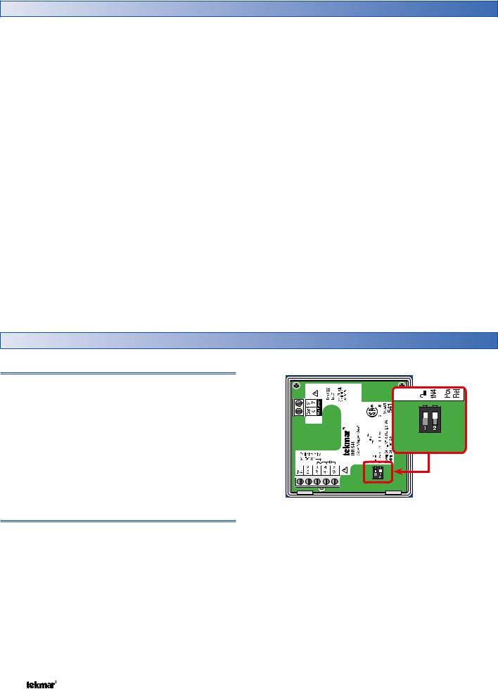
Table of Contents
Table of Contents............................................................ |
2 |
Cycles Per Hour ................................................... |
13 |
Display and DIP Switches .............................................. |
2 |
Heating Terminal Units ......................................... |
13 |
Dip Switches ........................................................... |
2 |
Heating Operation ................................................ |
14 |
Access Levels ......................................................... |
3 |
Cool Groups ......................................................... |
15 |
Display and Symbols Description............................ |
3 |
Setting the Schedule ............................................. |
15 |
User Interface ......................................................... |
4 |
Optimum Start / Stop ........................................... |
15 |
Setup .............................................................................. |
5 |
Scenes ................................................................. |
16 |
View Menu ............................................................. |
5 |
Away Hold ............................................................ |
17 |
Adjust Menu ............................................................ |
6 |
Offset ................................................................... |
17 |
Scene Menu............................................................ |
8 |
Units of Temperature ............................................ |
17 |
Schedule Menu ....................................................... |
9 |
Backlight .............................................................. |
17 |
Miscellaneous Menu .............................................. |
9 |
tN4 Address ......................................................... |
17 |
Thermostat Operation .................................................. |
11 |
Pump Exercising ................................................... |
17 |
Auxiliary Sensors ................................................. |
11 |
Error Messages ............................................................ |
18 |
Mode of Operation ............................................... |
11 |
Cleaning the Thermostat ............................................. |
24 |
Adjusting the Temperature ................................... |
12 |
Warranty ....................................................................... |
24 |
Display and DIP Switches
Dip Switches
tN4 System Control (DIP Switch #2)
A tN4 System Control is a control, not a thermostat, that the 541 thermostat connects to through the tN4 bus. All tN4 compatible Outdoor Reset Modules are tN4 System Controls.
•If the thermostat is connected to a tN4 System Control, set the tN4 System Control DIP switch to tN4 System Control (down position).
•If the thermostat is not connected to a tN4 System Control, set the tN4 System Control DIP switch to None (up position).
Lock / Unlock (DIP Switch #1)
Use the Lock / Unlock DIP switch to lock or unlock the Access Level of the 541.
•To unlock the Access Level, set the DIP switch to the unlocked (down) position.
•To lock the Access Level, set the DIP switch to the locked (up) position. Once locked, a padlock is displayed in the lower right corner of the display and the Access Level cannot be changed.
Note: The tN4 System Control’s Lock / Unlock DIP switch overrides the Lock / Unlock DIP switch on the 541. Set the tN4 System Control’s Lock / Unlock DIP switch to the Unlock position before Access Levels can be changed on the thermostat.
© 2007 |
D 541 - 08/07 |
2 of 24 |

Access Levels
The Access Level restricts the number of Menus, Items and Adjustments that can be accessed by the user. The Access Level setting is found in the Miscellaneous (MISC) menu. Select the appropriate access level for the people who work with the thermostat on a regular basis.
The 541 has five Access Levels:
•Advanced (ADV): access to all settings
•Installer (INST): settings required for installation
•User (USER): for property owners
•Limited (LTD): limited temperature adjustment
•Secure (SEC): for commercial and public installations
For more information, see the Misc (Miscellaneous) Menu section.
In the following menu tables, the access level the item is visible in is shown in the access column.
To adjust the Access Level:
1.Set the Unlock / Lock DIP switch to the unlock position. If a tN4 System Control is connected to the 541, the Unlock / Lock DIP switch on the tN4 System Control must be set to the unlock position.
2.Use the Menu button to select the Misc menu.
3.Use the Item button to select the Access menu item.
4.Use the Up and Down button to select the required Access Level.
Display
Menu Field
Displays the current menu
Status Field
Displays the current status of the control’s inputs, outputs and operation
Item Field
Displays an abbreviated name of the selected item
Number Field
Displays the current value of the selected item
Symbols Description
|
|
|
|
|
|
MODE OF OPERATION |
OPTIMUM START / STOP |
|
|
|
|
|
|
Displays whether the device is in heating |
The Optimum Start or Optimum Stop |
|
|
|
|
|
|
mode. |
feature is active. |
|
|
|
|
|
|
|
|
|
|
|
|
|
|
FIRST STAGE HEAT |
WARNING |
|
|
|
|
|
|
||
|
|
|
|
|
|
First stage heating is operating. |
An error is present. |
|
|
|
|
|
|
||
|
|
|
|
|
|
|
|
|
|
|
|
|
|
tN4 COMMUNICATION |
TEMPORARY HOLD |
|
|
|
|
|
|
The temperature has been temporarily |
|
|
|
|
|
|
|
A tN4 network is detected. |
|
|
|
|
|
|
|
adjusted from the scheduled event. |
|
|
|
|
|
|
|
|
|
|
|
|
|
|
|
|
|
|
|
|
|
|
|
LOCK |
SCHEDULED EVENT |
|
|
|
|
|
|
The Access Levels are locked. A menu |
|
|
|
|
|
|
|
Displays the current scheduled event. |
|
|
|
|
|
|
|
option is visible but not adjustable. |
|
|
|
|
|
|
|
|
|
|
|
|
|
|
|
|
|
3 of 24 |
© 2007 |
D 541 - 08/07 |

User Interface
Use the User Interface available on the Liquid Crystal Display (LCD) to setup and monitor the operation of the thermostat. Use the four push buttons below the LCD (Menu, Item, Up, Down) to select settings. As you enter settings, record the settings in the Job Record J 541.
Menu
The menus display in the Menu Field at the left of the LCD.
Five menus are available:
• |
View |
• |
Schedule |
• |
Adjust |
• |
Miscellaneous |
• |
Scene |
|
|
To select a menu, press and release the Menu button.
Item
In each menu, a group of items can be selected. The abbreviated name of the selected item displays in the Item field of the LCD display.
•To view the next available item, press and release the Item button.
•To view the previous item, hold down the Item button and press and release the Up button.
Adjusting a Setting
To adjust a setting:
1.Use the Menu button to select the appropriate menu.
2.Use the Item button to select a menu item.
3.Use the Up or Down button to adjust the setting.
Default Item
•To set the default item in the View Menu, display the item for more than five seconds.
After navigating menus, the display reverts back to the default item after 60 seconds of button inactivity.
Copy Settings
To save time in setting thermostats, you can copy the settings from one tN4 thermostat to a second tN4 thermostat.
Refer to the COPY item in the Misc menu on page 10.
Continue to next Item
Continue to next Item
Continue to next Menu
© 2007 |
D 541 - 08/07 |
4 of 24 |
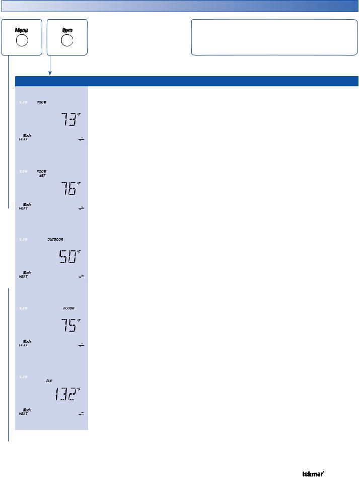
Display Menus
View Menu (1 of 1)
The View menu items display the current operating temperatures and status information of the system.
VIEW MENU
|
|
|
|
|
Item Field |
Range |
Access |
Description |
|
||
|
|
|
|
|
|
|
|
|
SEC |
ROOM |
SECTION A |
|
|
|
|
|
|
|
|
|
|||
|
|
|
|
|
|
|
|
|
|||
|
|
|
|
|
|
|
|
-58 to 212°F |
LTD |
Current air temperature in the room. |
|
|
|
|
|
|
|
|
|
USER |
Note: This item is only available when the Room |
||
|
|
|
|
|
|
|
|
(-50.0 to 100.0°C) |
|||
|
|
|
|
|
|
|
|
INST |
|||
|
|
|
|
|
|
|
|
|
Sensor is set to On or the Auxiliary Sensor is set to |
||
|
|
|
|
|
|
|
|
|
ADV |
Room. |
|
|
|
|
|
|
|
|
|
|
|
|
|
|
|
|
|
|
|
|
|
|
USER |
ROOM SET |
SECTION A |
|
|
|
|
|
|
|
|
|
|||
|
|
|
|
|
|
|
|
|
|||
|
|
|
|
|
|
|
|
– – –, 40 to 95°F |
Selected room temperature. |
|
|
|
|
|
|
|
|
|
|
INST |
Note: This item is only available when the Room |
||
|
|
|
|
|
|
|
|
(– – –, 4.5 to 35.0°C) |
|||
|
|
|
|
|
|
|
|
ADV |
|||
|
|
|
|
|
|
|
|
|
Sensor is set to On or the Auxiliary Sensor is set to |
||
|
|
|
|
|
|
|
|
|
|
Room. |
|
|
|
|
|
|
|
|
|
|
|
|
|
|
|
|
|
|
|
|
|
|
|
|
|
|
|
|
|
|
|
|
|
– – – (if no recent |
SEC |
OUTDOOR |
SECTION A |
|
|
|
|
|
|
|
|
||||
|
|
|
|
|
|
|
|
||||
|
|
|
|
|
|
|
|
LTD |
|||
|
|
|
|
|
|
|
|
Current temperature at the outdoor sensor. |
|||
|
|
|
|
|
|
|
|
message), |
|||
|
|
|
|
|
|
|
|
USER |
|||
|
|
|
|
|
|
|
|
-58 to 212°F |
Note: This item is only available when an outdoor |
||
|
|
|
|
|
|
|
|
INST |
|||
|
|
|
|
|
|
|
|
(-50.0 to 100.0°C) |
|||
|
|
|
|
|
|
|
|
sensor is connected to the tN4 network. |
|||
|
|
|
|
|
|
|
|
ADV |
|||
|
|
|
|
|
|
|
|
|
|||
|
|
|
|
|
|
|
|
|
|
|
|
|
|
|
|
|
|
|
|
|
|
|
|
|
|
|
|
|
|
|
|
|
SEC |
FLOOR |
SECTION A |
|
|
|
|
|
|
|
|
|
|||
|
|
|
|
|
|
|
|
|
|||
|
|
|
|
|
|
|
|
|
LTD |
||
|
|
|
|
|
|
|
|
-58 to 212°F |
Current floor temperature. |
|
|
|
|
|
|
|
|
|
|
USER |
|
||
|
|
|
|
|
|
|
|
(-50.0 to 100.0°C) |
Note: This item is only available when the Auxiliary |
||
|
|
|
|
|
|
|
|
INST |
|||
|
|
|
|
|
|
|
|
|
|||
|
|
|
|
|
|
|
|
|
Sensor is set to Floor. |
|
|
|
|
|
|
|
|
|
|
|
ADV |
|
|
|
|
|
|
|
|
|
|
|
|
||
|
|
|
|
|
|
|
|
|
|
|
|
|
|
|
|
|
|
|
|
|
|
|
|
|
|
|
|
|
|
|
|
|
|
SUPPLY TEMPERATURE OF TN4 BUS |
SECTION F |
|
|
|
|
|
|
|
|
|
|
||
|
|
|
|
|
|
|
|
|
INST |
Actual water temperature of the tN4 bus for the first |
|
|
|
|
|
|
|
|
|
-22 to 266°F |
stage of heat. |
|
|
|
|
|
|
|
|
|
|
(-30.0 to 130.0°C) |
ADV |
Note: This item is only available when the thermostat |
|
|
|
|
|
|
|
|
|
|
|
is connected to an Outdoor Reset Module and the |
|
|
|
|
|
|
|
|
|
|
|
||
|
|
|
|
|
|
|
|
|
|
DIP switch is set to tN4 System Control. |
|
|
|
|
|
|
|
|
|
|
|
||
|
|
|
|
|
|
|
|
|
|
|
|
 After the last item, the control returns to the first item in the menu.
5 of 24 |
© 2007 |
D 541 - 08/07 |

Adjust Menu (1 of 2)
The Adjust Menu items are the programmable settings used to operate the mechanical equipment.
ADJUST MENU
|
|
|
Item Field |
Range |
Access |
Description |
|
|
|
|
|
OFF, HEAT, |
USER |
MODE OF OPERATION |
SECTION B |
|
|
|
|
||||
|
|
|
|
||||
|
|
|
|
INST |
|||
|
|
|
|
Default = HEAT |
Mode of operation of the thermostat. |
|
|
|
|
|
|
ADV |
|
||
|
|
|
|
|
|
|
|
|
|
|
|
|
|
|
|
|
|
|
|
|
|
|
|
40 to 95°F |
|
|
|
|
|
|
|
|
|
|
|
|
|
|
|
|
|
|
|
|
|
|
|
|
|
|
|
|
|
|
|
|
|
|
|
(4.5 to 35.0°C) |
|
|
|
|
|
|
|
|
|
|
|
|
LTD |
SET HEAT |
SECTION C |
|
|
|
|
|
|
|
|
|
|||
|
|
|
|
|
|
|
|
|
Selected air heating temperature for each event. |
||
|
|
|
|
|
|
Wake |
Default = 70°F (21.0°C) |
USER |
|||
|
|
|
|
|
|
Note: At the Limited Access Level, you can only |
|||||
|
|
|
|
|
|
||||||
|
|
|
|
|
|
|
|
|
INST |
||
|
|
|
|
|
|
UnOccupied |
|
|
|||
|
|
|
|
|
|
Default = 62°F (16.5°C) |
adjust the temperature +/-3°F (1.5°C) from the last |
||||
|
|
|
|
|
|
ADV |
|||||
|
|
|
|
|
|
||||||
|
|
|
|
|
|
|
|
|
setting. |
|
|
|
|
|
|
|
|
Occupied |
Default = 70°F (21.0°C) |
|
|
||
|
|
|
|
|
|
|
|
|
|||
|
|
|
|
|
|
|
|
|
|||
|
|
|
|
|
|
|
|
|
|
|
|
|
|
|
|
|
|
Sleep |
Default = 62°F (16.5°C) |
|
|
|
|
|
|
|
|
|
|
|
|
|
|||
|
|
|
|
|
|
|
|
|
|
|
|
|
|
|
|
|
|
Away |
Default = 62°F (16.5°C) |
|
|
|
|
|
|
|
|
|
|
|
|
|
|||
|
|
|
|
|
|
|
|
|
|
|
|
|
|
|
|
|
|
|
|
OFF, 40 to 122°F |
|
FLOOR MINIMUM |
SECTION A |
|
|
|
|
|
|
|
|
|
|||
|
|
|
|
|
|
|
|
|
|||
|
|
|
|
|
|
|
|
|
|||
|
|
|
|
|
|
|
|
(OFF, 4.5 to 50.0°C) |
|
||
|
|
|
|
|
|
|
|
|
LTD |
Select the minimum floor temperature for each |
|
|
|
|
|
|
|
|
|
|
|||
|
|
|
|
|
|
|
|
|
event. |
|
|
|
|
|
|
|
|
|
|
|
USER |
|
|
|
|
|
|
|
|
|
|
|
|
||
|
|
|
|
|
|
Wake |
|
Default = 70°F (21.0°C) |
Note: This item is only available when the Auxiliary |
||
|
|
|
|
|
|
|
INST |
||||
|
|
|
|
|
|
|
|||||
|
|
|
|
|
|
|
|
|
ADV |
Sensor is set to Floor. At the Limited Access Level, |
|
|
|
|
|
|
|
UnOccupied |
|
Default = OFF |
|||
|
|
|
|
|
|
|
you can only adjust the temperature +/-3°F (1.5°C) |
||||
|
|
|
|
|
|
|
|
||||
|
|
|
|
|
|
|
|
|
|
from the last setting. |
|
|
|
|
|
|
|
Occupied |
|
Default = 70°F (21.0°C) |
|
|
|
|
|
|
|
|
|
|
|
|
|
||
|
|
|
|
|
|
|
|
|
|
||
|
|
|
|
|
|
Sleep |
|
Default = OFF |
|
|
|
|
|
|
|
|
|
|
|
|
|
||
|
|
|
|
|
|
|
|
|
|
|
|
|
|
|
|
|
|
|
|
40 to 122°F |
|
FLOOR MAXIMUM |
SECTION A |
|
|
|
|
|
|
|
|
|
|||
|
|
|
|
|
|
|
|
(4.5 to 50.0°C) |
ADV |
Maximum floor temperature. |
|
|
|
|
|
|
|
|
|
|
|||
|
|
|
|
|
|
|
|
|
|||
|
|
|
|
|
|
|
|
Default = 85°F |
Note: This item is only available when Sensor 1 is |
||
|
|
|
|
|
|
|
|
|
|||
|
|
|
|
|
|
|
|
(29.5°C) |
|
set to Floor. |
|
|
|
|
|
|
|
|
|
|
|
|
|
|
|
|
|
|
|
|
|
|
|
|
|
|
|
|
|
|
|
|
|
OFF, ROOM, |
|
SENSOR |
SECTION A |
|
|
|
|
|
|
|
|
|
|||
|
|
|
|
|
|
|
|
FLOR (Floor), |
INST |
||
|
|
|
|
|
|
|
|
||||
|
|
|
|
|
|
|
|
Select the type of sensor connected to the auxiliary |
|||
|
|
|
|
|
|
|
|
OUT (Outdoor) |
ADV |
||
|
|
|
|
|
|
|
|
|
sensor input. |
|
|
|
|
|
|
|
|
|
|
Default = OFF |
|
|
|
|
|
|
|
|
|
|
|
|
|
|
|
|
|
|
|
|
|
|
|
|
|
|
|
|
|
|
|
|
|
|
|
|
|
|
|
|
|
Continued on next page. |
|
|
|
|
|||||
© 2007 |
D 541 - 08/07 |
6 of 24 |

Adjust Menu (2 of 2)
ADJUST MENU
|
|
|
Item Field |
Range |
Access |
Description |
|
|||
|
|
|
|
|
|
|
OFF, ON |
INST |
ROOM SENSOR |
SECTION A |
|
|
|
|
|
|
|
||||
|
|
|
|
|
|
|
||||
|
|
|
|
|
|
|
||||
|
|
|
|
|
|
|
Default = ON |
ADV |
Selects whether the built-in room sensor is functional. |
|
|
|
|
|
|
|
|
|
|
|
|
|
|
|
|
|
|
|
|
|
|
|
|
|
|
|
|
|
|
|
|
HEAT CYCLES PER HOUR |
SECTION D |
|
|
|
|
|
|
|
SYNC, AUTO |
|
Select the number of heating cycles per hour. SYNC |
|
|
|
|
|
|
|
|
|
results in 5 CPH. All tN4 thermostats that are connected |
||
|
|
|
|
|
|
|
|
|||
|
|
|
|
|
|
|
2 to 12 |
ADV |
and have the SYNC setting selected synchronize their |
|
|
|
|
|
|
|
|
Default = AUTO |
|
cycle to the same starting time. |
|
|
|
|
|
|
|
|
|
|
Note: This item is only available when the tN4 System |
|
|
|
|
|
|
|
|
|
|
Control DIP switch is set to None. |
|
|
|
|
|
|
|
|
|
|
|
|
|
|
|
|
|
|
|
CTRL, HRF1, HRF2, |
|
HEAT 1 TERMINAL |
SECTION E |
|
|
|
|
|
|
|
|
|||
|
|
|
|
|
|
|
COIL, CONV, RAD, |
INST |
Select the type of heating terminal. |
|
|
|
|
|
|
|
|
|
|||
|
|
|
|
|
|
|
|
|||
|
|
|
|
|
|
|
BASE, OTHR |
ADV |
Note: If CTRL is selected, the terminal unit selected |
|
|
|
|
|
|
|
|
Default =CTRL |
|||
|
|
|
|
|
|
|
|
on the tN4 System Control is used. |
|
|
|
|
|
|
|
|
|
|
|
|
|
|
|
|
|
|
|
|
|
|
|
|
|
|
|
|
|
|
|
|
|
|
|
|
|
|
|
|
|
|
|
|
HEAT 1 PUMP |
SECTION F |
|
|
|
|
|
|
|
|
|
Select whether the system, primary, or mixing pump |
|
|
|
|
|
|
|
|
OFF, ON |
INST |
on a tN4 System Control must operate while the heat |
|
|
|
|
|
|
|
|
||||
|
|
|
|
|
|
|
is operating. |
|
||
|
|
|
|
|
|
|
Default = ON |
ADV |
|
|
|
|
|
|
|
|
|
Note: This item is only available when the H1 Terminal |
|||
|
|
|
|
|
|
|
|
|
||
|
|
|
|
|
|
|
|
|
item is set to CTRL, HRF1, HRF2, Fan Coil, Convector, |
|
|
|
|
|
|
|
|
|
|
||
|
|
|
|
|
|
|
|
|
Radiator, or Baseboard. |
|
|
|
|
|
|
|
|
|
|
|
|
|
|
|
|
|
|
|
|
|
|
|
|
|
|
|
|
|
|
|
|
HEAT 1 DELAY |
SECTION F |
|
|
|
|
|
|
|
|
|
Select whether the system, primary, or mixing pump |
|
|
|
|
|
|
|
|
|
|
||
|
|
|
|
|
|
|
OFF, ON |
INST |
on a tN4 System Control is delayed to allow a thermal |
|
|
|
|
|
|
|
|
motor zone valve to open. Select On for thermal motor, |
|||
|
|
|
|
|
|
|
||||
|
|
|
|
|
|
|
Default = OFF |
ADV |
select Off for zone pump or motorized zone valve. |
|
|
|
|
|
|
|
|
|
|
Note: This item is only available when the H1 Terminal |
|
|
|
|
|
|
|
|
|
|
item is set to CTRL, HRF1, HRF2, Fan Coil, Convector, |
|
|
|
|
|
|
|
|
|
|
||
|
|
|
|
|
|
|
|
|
||
|
|
|
|
|
|
|
|
|
Radiator, or Baseboard. |
|
|
|
|
|
|
|
|
|
|
|
|
|
|
|
|
|
|
|
|
|
COOL MEMBER |
SECTION G |
|
|
|
|
|
|
|
|
|
||
|
|
|
|
|
|
|
NONE, 1 to 16 |
|
Select the cool group of which this thermostat is a |
|
|
|
|
|
|
|
|
ADV |
member. Select None if this thermostat is not a cool |
||
|
|
|
|
|
|
|
||||
|
|
|
|
|
|
|
Default = NONE |
group member. |
|
|
|
|
|
|
|
|
|
|
|
||
|
|
|
|
|
|
|
|
Note: This item is only available when the thermostat |
||
|
|
|
|
|
|
|
|
|
||
|
|
|
|
|
|
|
|
|
is connected to a tN4 network. |
|
|
|
|
|
|
|
|
|
|
|
|
|
|
|
|
|
|
|
|
|
OPTIMUM START / STOP |
SECTION I |
|
|
|
|
|
|
|
|
|
||
|
|
|
|
|
|
|
ON, OFF |
INST |
Select whether to use Optimum Start / Stop for |
|
|
|
|
|
|
|
|
||||
|
|
|
|
|
|
|
heating. |
|
||
|
|
|
|
|
|
|
Default = ON |
ADV |
|
|
|
|
|
|
|
|
|
Note: This item is only available when a heating |
|||
|
|
|
|
|
|
|
|
|
||
|
|
|
|
|
|
|
|
|
schedule is selected. |
|
|
|
|
|
|
|
|
|
|
|
|
 After the last item, the control returns to the first item in the menu.
7 of 24 |
© 2007 |
D 541 - 08/07 |
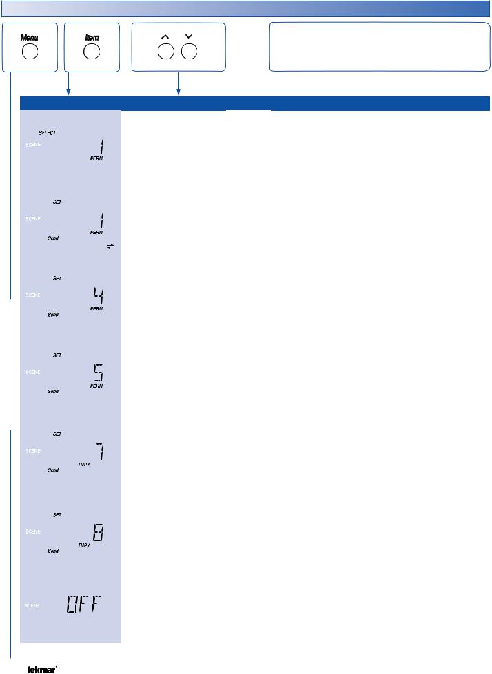
Scene Menu (1 of 1)
SCENE MENU
The Scene Menu items set the current scene as well as the scene settings.
|
|
Item Field |
Range |
Access |
Description |
|
|
|
|
|
|
Occ, Away, |
|
|
|
|
|
|
|
|
|
|
|
|
|
|
|
PERM1, Away 2 |
USER |
SELECT |
SECTION J |
|
|
|
|
PERM UnOcc 3, |
Select the scene for the building. |
|
|
|
|
|
|
PERM 4, PERM 5 |
INST |
|
|
|
|
|
|
Note: Only Occ and AWAY are available when no |
|||
|
|
|
|
TMPY Occ 6 |
ADV |
||
|
|
|
|
TMPY 7, TMPY 8 |
schedule is selected. |
|
|
|
|
|
|
|
|
||
|
|
|
|
Default = PERM 1 |
|
|
|
|
|
|
|
|
|
|
|
|
|
|
|
Schd |
|
|
|
|
|
|
|
|
|
|
|
|
|
|
|
Wake |
|
SET PERMANENT 1 |
SECTION J |
|
|
|
|
Occ |
INST |
||
|
|
|
|
Select an action for the Permanent 1 scene. |
|||
|
|
|
|
UnOcc |
|||
|
|
|
|
||||
|
|
|
|
ADV |
Note: This item is only available when SCENE menu |
||
|
|
|
|
Sleep |
|||
|
|
|
|
Away |
|
is set to ON and a schedule has been selected. |
|
|
|
|
|
Default = SCHD |
|
|
|
|
|
|
|
|
|
|
|
|
|
|
|
Schd |
|
|
|
|
|
|
|
Wake |
|
SET PERMANENT 4 |
SECTION J |
|
|
|
|
Occ |
|
||
|
|
|
|
INST |
Select an action for the Permanent 4 scene. |
||
|
|
|
|
UnOcc |
|||
|
|
|
|
||||
|
|
|
|
ADV |
|
|
|
|
|
|
|
Sleep |
Note: This item is only available when SCENE menu |
||
|
|
|
|
Away |
|
is set to ON and a schedule has been selected. |
|
|
|
|
|
Default = SCHD |
|
|
|
|
|
|
|
|
|
|
|
|
|
|
|
Schd |
|
|
|
|
|
|
|
|
|
|
|
|
|
|
|
Wake |
|
SET PERMANENT 5 |
SECTION J |
|
|
|
|
Occ |
|
||
|
|
|
|
INST |
Select an action for the Permanent 5 scene. |
||
|
|
|
|
UnOcc |
|||
|
|
|
|
||||
|
|
|
|
ADV |
|
|
|
|
|
|
|
Sleep |
Note: This item is only available when SCENE menu |
||
|
|
|
|
Away |
|
is set to ON and a schedule has been selected. |
|
|
|
|
|
Default = SCHD |
|
|
|
|
|
|
|
|
|
|
|
|
|
|
|
Schd |
|
SET TEMPORARY 7 |
SECTION J |
|
|
|
|
|
|||
|
|
|
|
Wake |
|
||
|
|
|
|
|
Select an action for the Temporary 7 scene. The |
||
|
|
|
|
Occ |
INST |
||
|
|
|
|
UnOcc |
scene lasts for 4 hours before reverting to the previous |
||
|
|
|
|
||||
|
|
|
|
Sleep |
ADV |
permanent scene. |
|
|
|
|
|
Away |
|
Note: This item is only available when SCENE menu |
|
|
|
|
|
Default = SCHD |
|
is set to ON and a schedule has been selected. |
|
|
|
|
|
|
|||
|
|
|
|
|
|
|
|
|
|
|
|
Schd |
|
SET TEMPORARY 8 |
SECTION J |
|
|
|
|
Wake |
|
||
|
|
|
|
|
Select an action for the Temporary 8 scene. The |
||
|
|
|
|
Occ |
INST |
||
|
|
|
|
UnOcc |
scene lasts for 8 hours before reverting to the previous |
||
|
|
|
|
||||
|
|
|
|
|
|||
|
|
|
|
Sleep |
ADV |
permanent scene. |
|
|
|
|
|
Away |
|
Note: This item is only available when SCENE menu |
|
|
|
|
|
Default = SCHD |
|
is set to ON and a schedule has been selected. |
|
|
|
|
|
|
|||
|
|
|
|
|
|
|
|
|
|
|
|
OFF, ON |
INST |
SCENE MENU |
SECTION J |
|
|
|
|
||||
|
|
|
|
||||
|
|
|
|
Default = OFF |
ADV |
Select the Scene feature of the thermostat. |
|
|
|
|
|
|
|
|
|
|
|
|
|
|
|
|
|
 After the last item, the control returns to the first item in the menu.
© 2007 |
D 541 - 08/07 |
8 of 24 |
 Loading...