


- Data Brochure |
D 374 |
Universal Reset Control 374 |
03/09 |
|
|
The tekmar Universal Reset Control 374 is designed to maximize the comfort and efficiency provided by a hydronic heating system. The control automatically adjusts the boiler and mix water temperatures that are delivered to the heating system by using outdoor reset. The 374 can control two separate on / off stages (or one low / high fire) to provide outdoor reset while providing equal run time rotation of the boilers. The 374 can operate two mixing devices, which can be either two variable speed injection pumps or two floating action valves. The mixing devices can be used to supply two different reset water temperatures or one reset and one setpoint water temperature to a space heating system. The 374 is capable of controlling an indirect Domestic Hot Water (DHW) storage tank and setpoint load. A large easy to read display provides current system temperatures and operating status. The control has an internal timer, which can have 2 events per day on a 24 hour, 5-1-1 day or 7 day schedule.
Additional functions include:
•Outdoor Reset
•Two Mixing Devices
•Two Boiler Stages
•Two separate mix demands for space heating loads
•Boiler demand for space heating loads
•DHW demand for domestic hot water loads
•Setpoint demand for setpoint loads
•Installer and Advanced access levels
•Primary pump and mixing system pump outputs
•Exercising
•Test sequence to ensure proper component operation
•Internal setback timer for energy savings
•Setback input for energy savings
•CSA C US certified
|
Rotate |
Floating |
|
|
Setback |
30% Enable Return |
|
Boiler Demand |
Advanced |
||
|
Boiler Sensor |
||
Mix 1 Demand |
|
||
Installer |
Supply |
||
|
|||
Mix 2 Demand |
|
O 10% Enable |
|
DHW Demand |
|
Variable |
|
|
Test |
||
Setpoint Demand |
|
|
|
|
|
Menu |
Item |
|
|
|
||
|
Universal Reset Control 374 |
|||||||||
|
Two Mixing, Two Stage Boiler, DHW & Setpoint |
|||||||||
Output |
|
|
|
|
|
|
Do not apply power |
|||
1 |
2 |
3 |
4 |
5 |
6 |
7 |
8 |
9 |
10 11 12 |
|
Mixing |
Opn Cls1 Pwr Opn Cls2 |
UnO Com Boil |
Out Com Mix1 Mix2 |
|||||||
Valve & |
1 |
Var1 |
Mix |
2 |
Var2 |
Sw |
|
|
|
|
Actuating |
|
|
|
|
|
|
|
|
|
|
Motor |
OR |
|
|
|
|
|
|
|
|
|
Output |
|
|
|
|
|
|
|
|
|
|
Variable |
|
|
|
|
|
|
|
|
|
|
Speed |
|
|
|
|
|
|
|
|
|
|
driven |
|
|
|
|
|
|
|
|
|
|
pump |
|
|
|
|
|
|
|
|
|
|
Output |
|
|
|
|
|
|
|
|
|
|
Mixing |
|
|
|
|
|
|
|
|
|
|
Valve & |
|
|
|
|
|
|
|
|
|
|
Actuating |
|
|
|
|
|
|
|
|
|
|
Motor |
OR |
|
|
|
|
|
|
|
|
|
Output |
|
|
|
|
|
|
|
|
|
|
Variable |
|
|
|
|
|
|
|
|
|
|
Speed |
|
|
|
|
|
|
|
|
|
|
driven |
|
|
|
|
|
|
|
|
|
|
pump |
|
|
|
|
|
|
|
|
|
|
Input |
|
|
|
|
|
|
|
|
|
|
032 Timer |
|
|
|
|
|
|
|
|
|
|
Optional |
|
|
|
|
|
|
|
|
|
|
Input |
|
|
|
|
|
|
|
|
|
|
Universal |
|
|
|
|
|
|
|
|
|
|
Sensor |
|
|
|
|
|
|
|
|
|
|
Included |
Input |
|
|
|
|
|
|
|
|
|
|
|
|
Input |
|
|
Input |
||||
|
Outdoor |
|
Universal |
|
|
Universal |
||||
|
Sensor |
|
|
Sensor |
|
|
Sensor |
|||
|
Included |
|
Included |
|
|
Included |
||||
|
|
o |
not testing |
|
|
red |
testing |
|
|
red |
testing paused |
|
|
For maximum heat, |
|
|
|
press & hold Test |
|
|
|
button for 3 seconds. |
|
|
|
|
Meets Class B: |
|
|
|
|
|
|
|
|
|
|
|
|
Made in Canada by |
Canadian ICES |
||
tekmar Control Systems Ltd. |
FCC Part 15 |
||
|
|||
Power: |
115 V ±10% 50/60 Hz 1750 VA |
||
Relays: |
230 V (ac) 5 A 1/3 hp, pilot duty 240 VA |
||
Variable Pump: |
230 V (ac) 2.4 A 1/6 hp, fuse T2.5 A |
||
Demands: |
20 to 260 V (ac) 2 VA |
Code |
|
|
|||
Signal wiring must be rated at least 300 V. |
Date |
||
|
|
|
|
13 14 15 16 17 18 19 20 21 22 23 24 25 26 27 28 29 30 31 |
H2036B |
||||||
Mix1 |
Power |
Prim Mix2 |
|
DHW |
Stage 1/ Stage 2/ Mix1 Com Mix2 Setp DHW Boil Com |
||
|
|
||||||
P2 |
L |
N |
P1 P3 |
N |
Pmp/Vlv |
Boil Enbl. Setp Enbl. Dem Dem Dem Dem Dem Dem Dem |
|
OR
Note:
Boiler, DHW, setpoint, or mixed demand must be powered with 20 to 260 V (ac) before the control will operate pump/valve outputs or the boiler is able to fire.
Input
Boiler
Demand
Input
DHW
Demand
Input
Setpoint
Demand
Input
Mix 2
Demand
Input
Mix 1
Demand
Output
Boiler
Output |
Input |
Output |
Output |
Output |
Output |
Mix 1 |
115 V (ac) |
Primary |
Mix 2 |
DHW |
DHW |
System |
Power |
Pump |
System |
Pump |
Valve |
Pump |
Supply |
|
Pump |
|
|
1 of 36 |
© 2009 |
D 374 - 03/09 |

How To Use The Data Brochure
This brochure is organized into four main sections. They are: 1) Sequence of Operation, 2) Installation, 3) Control Settings, and 4) Testing and Troubleshooting. The Sequence of Operation section has five sub-sections. We recommend reading Section A: General of the Sequence of Operation, as this contains important information on the overall operation of the control. Then read the sub sections that apply to your installation.
The Control Settings section (starting at DIP Switch Settings) of this brochure describes the various items that are adjusted and displayed by the control. The control functions of each adjustable item are described in the Sequence of Operation.
Table of Contents
User Interface.................................................. |
Pg 2 |
Control Settings.............................................. |
Pg 25 |
Display ............................................................. |
Pg 3 |
View Menu .............................................. |
Pg 25 |
Sequence of Operation .................................. |
Pg 4 |
Adjust Menu ........................................... |
Pg 26 |
Section A: General Operation .............. |
Pg 4 |
Time Menu .............................................. |
Pg 30 |
Section B: Boiler Operation.................. |
Pg 6 |
Schedule Menu ...................................... |
Pg 31 |
Section C: DHW Operation ................... |
Pg 10 |
Testing the Control ......................................... |
Pg 32 |
Section D: Setpoint Operation ............. |
Pg 12 |
Error Messages............................................... |
Pg 34 |
Section E: Mixing Operation................. |
Pg 13 |
Technical Data................................................. |
Pg 36 |
Installation....................................................... |
Pg 16 |
Limited Warranty ............................................ |
Pg 36 |
DIP Switch Settings........................................ |
Pg 23 |
|
|
User Interface
The 374 uses a Liquid Crystal Display (LCD) as the method of supplying information. You use the LCD in order to setup and monitor the operation of your system. The 374 has four push buttons (Menu, Item, ▲, ▼) for selecting and adjusting settings. As you program your control, record your settings in the ADJUST Menu table which is found in the second half of this brochure.
Menu
All of the items displayed by the control are organized into four menus: View, Adjust, Time, and Schedule. These menus are listed on the top left hand side of the display (Menu Field). To select a menu, use the Menu button. By pressing and releasing the Menu button, the display will advance to the next available menu. Once a menu is
selected, there will be a group of items that can be viewed within the menu.
Menu Item
Note: The TIME and SCHEDULE menus are not available when there is no Setback selected.
Item
The abbreviated name of the selected item will be displayed in the item field of the display. To view the next available item, press and release the Item button. Once you have reached the last available item in a menu, pressing and releasing the Item button will return the display to the first item in the selected menu.
Menu Item
The items can be quickly scrolled through by holding the Item button and then pressing the ▼ button. To rapidly scroll through the items in the reverse order, hold the Item button and press the ▲ button.
Adjust
To make an adjustment to a setting in the control, begin by selecting the appropriate menu using the Menu button. Then select the desired item using the Item button. Finally, use the ▲ and / or ▼ button to make the adjustment.
Additional information can be gained by observing the Status field of the LCD. The status |
Menu Item |
||
|
|||
field will indicate which of the control’s outputs are currently active. Most symbols in the |
|
||
status field are only visible when the VIEW Menu is selected. |
|
||
© 2009 |
D 374 - 03/09 |
2 of 36 |
|

Display
Menu Field
Displays the current menu
Item Field
Displays an abbreviated name of the selected item
Status Field
Displays the current status of the control's inputs, outputs and operation
Symbol Description
Open / Close
Displays when the actuator is opening or closing the mixing valve.
Mixing Device Output Scale
Shows output of injection pump or mixing valve.
Burner
Displays which stage relay is turned on.
Pump
Displays when the primary pump 1, mix 1 system pump and mix 2 system pump is operating.
DHW
Displays when the DHW pump or valve is on.
Warning
Displays when an error exists or when a limit has been reached.
Number Field
Displays the current value of the selected item
Boiler Demand
Mix 1 Demand
Mix 2 Demand
DHW Demand
Setpoint Demand
Time & Date Field
Displays days and
AM or PM
Buttons
Selects Menus, Items and adjust settings
Installer Access Level
Displays when the Installer / Advanced Dip switch is set to Installer
°F, °C, min
Units of measurement.
Pointer
Displays the control operation as indicated by the text.
UnOccupied Schedule
Displays when the control is in UnOccupied Mode.
Occupied Schedule
Displays when the control is in Occupied Mode.
Definitions
The following defined terms and symbols are used throughout this manual to bring attention to the presence of hazards of various risk levels, or to important information concerning the life of the product.
-Warning Symbol: Indicates presence of hazards which can cause severe personal injury, death or substantial property damage if ignored.
-Double insulated
INSTALLATION
CATEGORY II |
- Local level, appliances |
3 of 36 |
© 2009 |
D 374 - 03/09 |

Sequence of Operation
Section A |
|
Section B |
|
Section C |
|
Section D |
|
Section E |
General |
|
Boiler |
|
DHW |
|
Setpoint |
|
Mixing |
Operation |
|
Reset |
|
Operation |
|
Operation |
|
Operation |
Page 4 - 6 |
|
Page 6 - 9 |
|
Page 10 - 12 |
|
Page 12 |
|
Page 13 - 15 |
|
|
|
|
|
|
|
|
|
Section A: General Operation
POWERING UP THE CONTROL
When the 374 control is powered up, all segments in the LCD are turned on for 2 seconds. Next, the control displays the control type number in the LCD for 2 seconds. Next, the software version is displayed for 2 seconds. Finally, the control enters into the normal operating mode.
TYPES OF DEMANDS
The control can control the supply water temperatures of two mix temperature systems and the boiler supply water temperature. The type of demand the control receives determines the operation of the control.
Boiler Demand
When a boiler demand signal from the heating system is present, the control operates the boiler(s) to maintain the boiler supply temperature based on the outdoor air temperature and the Boiler Characterized Heating Curve settings. Refer to section B.
DHW Demand
When a DHW demand is present, the control operates the boiler(s) to maintain the supply water temperature at least as hot as the DHW exchange setting. Refer to section C.
Setpoint Demand
When a setpoint demand signal is present, the control operates the boiler(s) to maintain the supply water temperature at least as hot as the Setpoint setting. Refer to section D.
Mix 1 Demand
When a mix 1 demand signal from the heating system is present, the control operates the mixing 1 device and the boiler(s) to maintain the mix 1 supply temperature based on the outdoor air temperature and the Mix 1 Characterized Heating Curve settings. Refer to section E.
Mix 2 Demand
When a mix 2 demand signal from the heating system is present, the control operates the mixing 2 device and boiler(s) to maintain the mix 2 supply temperature based on the outdoor air temperature and the Mix 2 Characterized Heating Curve settings or the control can provide a setpoint temperature. Refer to section E.
|
|
Design Supply |
|
CHARACTERIZED HEATING CURVE |
|
|
|
The control varies the supply water temperature based on the outdoor air |
Terminal Unit |
|
Temperature |
to a space using different proportions of radiation, natural convection |
|
||
|
|
||
temperature. The control takes into account the type of terminal unit that |
|
|
|
the system is using. Since different types of terminal units transfer heat |
Indoor Design |
Outdoor Design |
|
and forced convection, the supply water temperature must be controlled |
|
|
Water |
differently. Once a terminal unit is selected, the control varies the supply |
|
|
|
|
|
Increasing |
|
water temperature according to the type of terminal unit. This improves |
|
|
|
|
|
|
|
the control of the air temperature in the building. |
|
|
|
|
Decreasing Outdoor Temperature |
|
|
TERMINAL UNITS
The control provides for a selection between six different terminal unit types: two types of radiant floor heat, fancoil, fin-tube convector, radiator and baseboard. When a terminal unit is selected, the control automatically loads the design supply temperature, maximum supply temperature, and minimum supply temperature. See section B for Boiler Terminal Units and section E for Mixing Terminal Units.
High Mass Radiant (1)
This type of a hydronic radiant floor is embedded in either a thick concrete or gypsum pour. This heating system has a large thermal mass and is slow acting.
|
|
|
|
|
|
|
|
|
|
|
|
© 2009 |
D 374 - 03/09 |
4 of 36 |
|
|
|
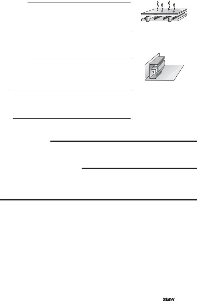
Low Mass Radiant (2)
This type of radiant heating system is either attached to the bottom of a wood sub-floor, suspended in the joist space, or sandwiched between the sub-floor and the surface. This type of radiant system has a relatively low thermal mass and responds faster than a high mass system.
Fancoil (3)
A fancoil terminal unit or Air Handling Unit (AHU) consists of a hydronic heating coil and either a fan or blower. Air is forced across the coil at a constant velocity by the fan or blower, and is then delivered into the building space.
Fin-Tube Convector (4)
A convector terminal unit is made up of a heating element with fins on it. This type of terminal unit relies on the natural convection of air across the heating element to deliver heated air into the space. The amount of natural convection to the space is dependant on the supply water temperature to the heating element and the room air temperature.
Radiator (5)
A radiator terminal unit has a large heated surface that is exposed to the room. A radiator provides heat to the room through radiant heat transfer and natural convection.
Baseboard (6)
A baseboard terminal unit is similar to a radiator, but has a low profile and is installed at the base of the wall. The proportion of heat transferred by radiation from a baseboard is greater than that from a fin-tube convector.
OUTDOOR DESIGN TEMPERATURE
The outdoor design temperature is the outdoor air temperature that is the typical coldest temperature of the year where the building is located. This temperature is used when doing the heat loss calculations for the building. If a cold outdoor design temperature is selected, the supply water temperature rises gradually as the outdoor temperature drops. If a warm outdoor design temperature is selected, the supply water temperature rises rapidly as the outdoor temperature drops.
WARM WEATHER SHUT DOWN (OCC AND UNOCC)
The Warm Weather Shut Down (WWSD) disables the space heating system during warm outdoor weather. There is a separate WWSD for both the occupied and the unoccupied periods. When the outdoor air temperature rises above the WWSD setting, the control turns on the WWSD pointer in the display and does not operate the space heating system to satisfy boiler, mix 1 or mix 2 demands. Mix 2 setpoint demands remain active. The control does respond to a DHW demand or a setpoint demand and operates as described in sections C and D.
SETBACK
To provide greater energy savings, the control has a setback feature. With setback, the supply water temperature in the system is reduced when the building is unoccupied. By reducing the supply water temperature, the air temperature in the space may be reduced even when thermostat(s) are not turned down.
The control has an internal setback timer with two events per day on a 24 hour, a 5-1-1 day or a 7 day schedule.
The control also has an external setback input. Any time the UnO Sw (6) and the Com (7) are shorted together, the control operates in the unoccupied mode.
The external setback overrides the internal setback timer schedule to place the control into the unoccupied period.
When in the unoccupied mode, the UNOCC segment is displayed in the LCD. The control adjusts the supply water temperature based on the UNOCC settings made in the control.
FACTORY DEFAULTS
6 |
7 |
Uno |
Com |
Sw |
|

 Timer Switch
The control comes preset with several factory defaults. These defaults are based on the terminal unit selection (see section B for Boilers and section E for Mixing Devices). To fine-tune building requirements, these defaults may be changed.
To reload the factory default, power down the control and wait for 10 seconds. Power up the control while simultaneously holding the Menu and ▼ buttons. An E01 error occurs forcing the installer to go through the ADJUST menu to ensure the settings are correct.
5 of 36 |
© 2009 |
D 374 - 03/09 |
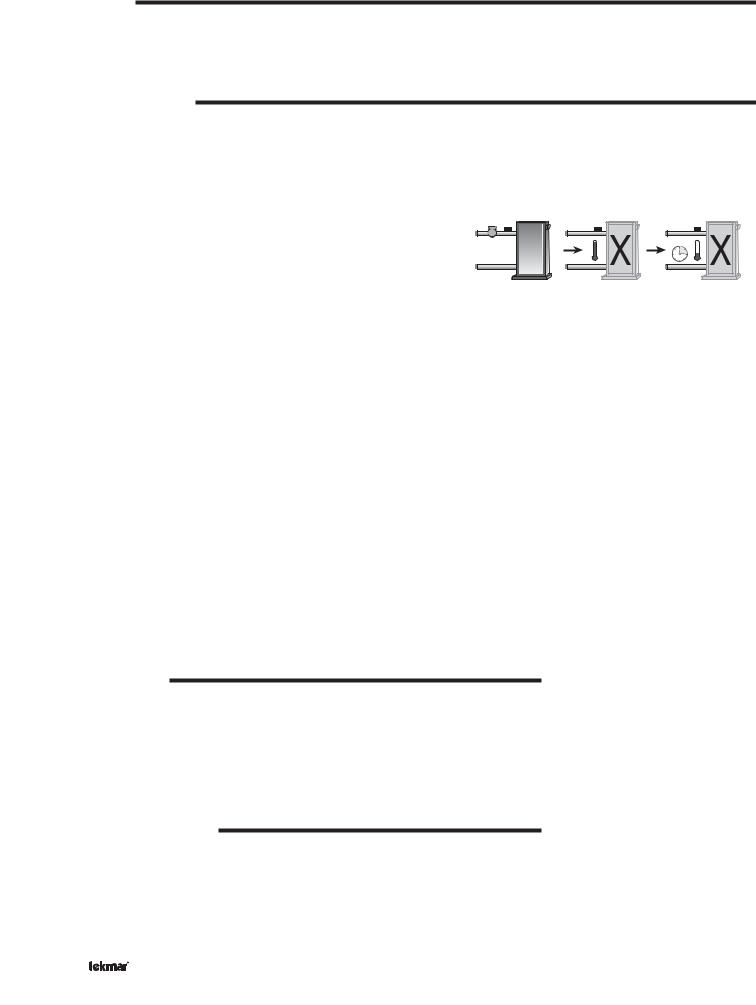
EXERCISING
The control has a built-in exercising feature, which ensures that each pump or valve is operated at least once every 3 days. If a pump has not been operated at least once every 3 days, the control turns on the output for 10 seconds. This minimizes the possibility of the pump seizing during a long period of inactivity. While the control is exercising, the Test LED flashes quickly.
Note: The exercising function does not work if power to the control or pumps is disconnected.
BOILER PROTECTION
The control is capable of providing boiler protection from cold mixing system return temperatures. The control protects the boilers by either reducing the variable speed injection pump speeds or by closing the four way valves. This limits the amount of cool return water to the boiler and allows the boiler water temperature to recover.
PRIMARY PUMP OPERATION
The primary pump operates when the control receives boiler, mix 1 or mix 2 demands and is not in Warm Weather Shut Down (WWSD). The primary pump will operate in DHW MODES 3 and 4 when a DHW demand is present. The primary pump also operates in Setpoint MODE 3 during setpoint demands.
Primary Pump Purge
After any demand that operates the primary pump is removed, the control continues to operate the primary pump for an additional 20 seconds.
Section B: Boiler Operation
Section B1 |
|
Section B2 |
Boiler |
|
Boiler |
Reset |
|
Enable |
|
|
|
Section B1: Boiler Reset
BOILER DEMAND
A boiler demand is required in order for the control to provide heat to the heating system. A boiler demand is generated by applying a voltage between 24 and 230 V (ac) across the Boil Dem and Com Dem terminals (30 and 31). Once voltage is applied, the Boiler Demand pointer is displayed in the LCD. If the control is not in Warm Weather Shut Down (WWSD), the control closes the primary pump contact. The control calculates a boiler target supply temperature based on the outdoor air temperature and the boiler characterized heating curve settings. The control then fires the boiler(s), if required, to maintain the boiler target supply temperature.
BOILER SUPPLY SENSOR
The boiler sensor can be located on the boiler supply if the 374 is the only control that is operating the boiler(s). When the Return / Supply DIP switch is set to Supply, the control determines the required operating temperature for the boiler supply and operates the Stage 1 and Stage 2 contacts in order to maintain the correct boiler supply water temperature.
30 |
31 |
Boil |
Com |
Dem |
Dem |
|
24 to 230 V (ac)
Boiler |
Sensor |
© 2009 |
D 374 - 03/09 |
6 of 36 |
BOILER CHARACTERIZED HEATING CURVE
The boiler(s) have a Boiler Characterized Heating Curve determined by the following settings:
Boiler Design Temperature
The boiler design supply temperature is the supply water temperature required to heat the building when the outdoor air temperature is as cold as the outdoor design temperature.
Boiler Indoor Design Temperature
The indoor design temperature is the room temperature that was used in the original heat loss calculations for the building. This setting establishes the beginning of the boiler characterized heating curve.
Boil Room
The Boil Room setting is the desired room temperature for the building and provides a parallel shift of the boiler characterized heating curve. The room temperature desired by the occupants is often different from the design indoor temperature. If the room temperature is not correct, adjusting the Boil Room setting increases or decreases the amount of heat available to the boiler zones in the building. A Boil Room setting is available for both the occupied (day) and unoccupied (night) periods.
BOILER TERMINAL UNITS
|
|
|
|
|
|
210 |
|
|
|
|
|
|
|
(99) |
|
Boiler Characterized |
BOIL DSGN |
BOIL MAX |
|
||||
|
Heating Curve |
|
|
|
190 |
|
|
|
|
|
|
(88) |
|
||
|
|
|
|
|
|
|
|
|
|
|
|
|
|
170 |
Temperature |
|
|
|
|
|
|
(77) |
|
|
BOIL MIN |
|
|
|
|
150 |
|
|
|
|
|
|
(66) |
||
|
|
|
|
|
|
||
|
|
|
|
|
|
130 |
|
|
|
|
|
|
|
Water |
|
|
|
|
|
|
|
(54) |
|
|
|
|
|
OUT DSGN |
|
110 |
|
|
|
|
|
|
|
||
|
|
|
|
|
|
Supply |
|
|
|
|
|
|
|
(43) |
|
|
|
|
WWSD OCC |
|
90 |
||
BOIL INDR |
|
WWSD UNOCC |
|
||||
|
|
(32) |
|
||||
|
|
|
|
|
|
|
|
|
|
|
ROOM OCC |
|
70 |
|
|
|
|
|
|
(21) |
|
||
|
|
|
|
|
|
|
|
|
|
|
ROOM UNOCC |
|
50°F |
|
|
|
|
|
|
|
|
|
|
80 |
60 |
40 |
|
20 |
0 |
(10°C) |
|
|
-20 |
|
|||||
(27) |
(16) |
(5) |
|
(-7) |
(-18) |
(-29) |
|
Outdoor Air Temperature
When a terminal unit is selected, the control automatically loads the boiler design temperature, boiler maximum supply temperature, and boiler minimum supply temperature. The factory defaults can be changed to better match the installed system. If a factory default has been changed, refer to section A to reload the factory defaults.
Terminal Unit |
High Mass |
Low Mass |
Fancoil |
Fin-Tube |
Radiator |
Baseboard |
|
Radiant (1) |
Radiant (2) |
(3) |
Convector (4) |
(5) |
(6) |
BOIL DSGN |
120°F (49°C) |
140°F (60°C) |
190°F (88°C) |
180°F (82°C) |
160°F (71°C) |
150°F (66°C) |
|
|
|
|
|
|
|
BOIL MAX |
140°F (60°C) |
160°F (71°C) |
210°F (99°C) |
200°F (93°C) |
180°F (82°C) |
170°F (77°C) |
BOIL MIN |
OFF |
OFF |
140°F (60°C) |
140°F (60°C) |
140°F (60°C) |
140°F (60°C) |
|
|
|
|
|
|
|
Boiler Target Temperature
The boiler target temperature is determined from the boiler characterized heating curve settings and the outdoor air temperature. The control displays the temperature that it is currently trying to maintain as the boiler supply temperature. If the control does not presently have a requirement for heat, it does not show a boiler target temperature. Instead, “– – –” is displayed in the LCD.
Boiler Minimum
The boiler minimum is the lowest temperature that the control is allowed to use as a boiler target temperature. During mild conditions, if the control calculates a boiler target temperature that is below the boiler minimum setting, the boiler target temperature is adjusted to at least the boiler(s) minimum setting. During this condition, if the boiler(s) is operating, the minimum segment is turned on in the display when viewing either the boiler supply temperature or the boiler target temperature. Set the boiler minimum setting to the boiler manufacturer’s recommended temperature.
Boiler Maximum
The boiler maximum is the highest temperature that the control is allowed to use as a boiler target temperature. If the control does target the boiler maximum setting, and the boiler temperature is near the boiler maximum temperature, the maximum segment will be displayed in the LCD while either the boiler target temperature or the boiler supply temperature is being viewed. At no time does the control operate the boiler(s) above 248°F (120°C).
MIN Segment On 

|
|
|
|
|
|
|
|
|
|
|
|
|
|
|
|
|
|
|
|
|
|
|
|
|
|
|
|
|
|
|
|
|
|
|
|
|
|
|
|
MAX Segment |
|
|
MAX Segment |
|
|
|
|||||
|
|
|
|
|
|
|||||||
|
On |
|
|
|
On |
|
|
|
||||
7 of 36 |
© 2009 |
D 374 - 03/09 |
STAGING
The control operates up to two on / off boiler stages (or one low / high fire) in order to provide the required supply temperature. After a stage is turned on in the firing sequence, the control waits for a minimum time delay. The minimum time delay is adjustable using the Stage Delay setting. After the Stage Delay has expired, the control examines the control error to determine when the next stage is to fire. The control error is determined using Proportional, Integral and Derivative (PID) logic.
Proportional – compares the actual supply temperature to the boiler target temperature. The colder the supply water temperature, the sooner the next stage is turned on.
Integral – compares the actual supply temperature to the boiler target temperature over a period of time.
Derivative – compares how fast or slow the supply water temperature is changing. If the supply temperature is increasing slowly, the next stage is turned on sooner. If the supply temperature is increasing quickly, the next stage is turned on later, if at all.
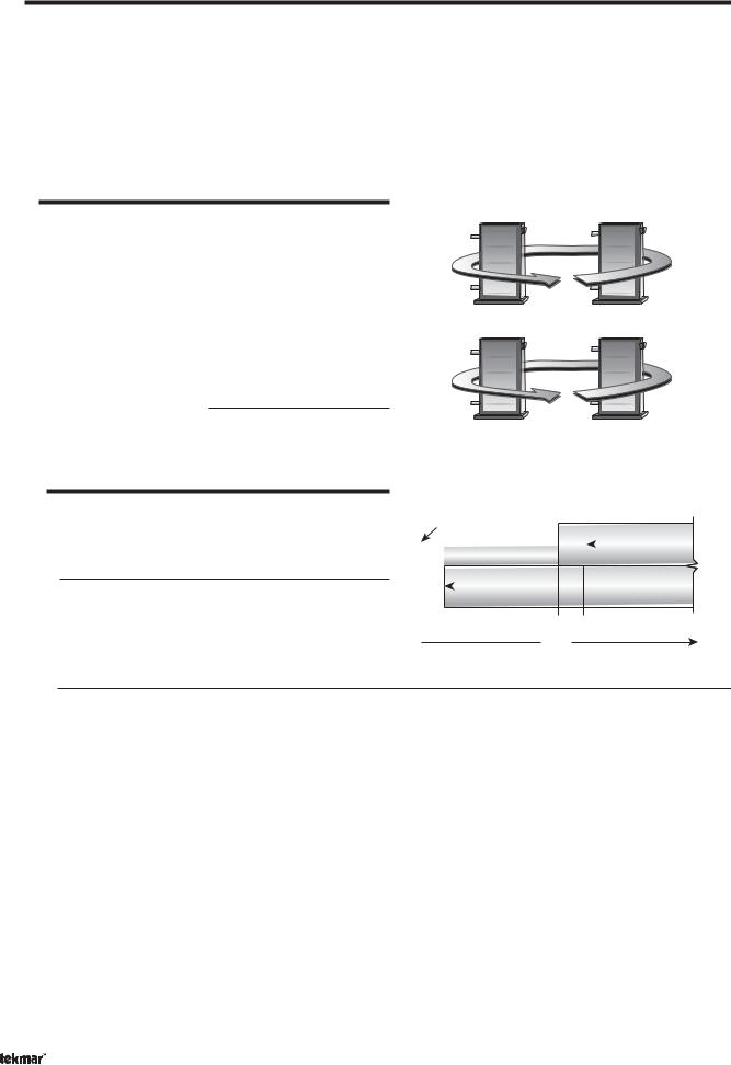
ROTATION
The control’s Equal Run Time Rotation function is fixed at 48 hours. The firing order of the boilers changes whenever one boiler accumulates 48 hours more running time than the other boiler. After each rotation, the boiler with the least running hours is the first to fire and the boiler with the most running hours is the last to fire. This function ensures that both boilers receive equal amounts of use. When the Rotate / Off DIP switch is set to the Off position, the firing sequence always begins with boiler one and then boiler two.
Note: When using a single two-stage boiler, ensure that the Rotate / Off DIP switch is set to Off.
Resetting the Rotation Sequence
To reset the rotation sequence, set the Rotate / Off DIP switch to the Off setting for 5 seconds and then return the DIP switch to the Rotate setting.
FIRE DELAY
The Fire Delay is the time delay that occurs between the time that the control closes a stage contact to fire a stage and the burner fires for that stage.
Stage Delay
The stage delay is the minimum time delay between the firing of stages. After this delay has expired the control can fire the next stage if it is required. This setting can be adjusted manually or set to an automatic setting. When the automatic setting is used, the control determines the best stage delay based on the operation of the system.
Boiler Mass
1 |
2 |
720 hours |
672 hours |
2 |
1 |
672 hours |
720 hours |
|
Boiler Contact Closes |
|
|
|
|
|||
#1 |
|
|
|
#2 |
|
|
|
|
|
|
|
Boiler |
|
|
Boiler #2 Fires |
||
|
|
|
|
|
|
|
|
|
|
|
|
|
Stage Delay |
|
|
|
|
|
Boiler |
|
|
Boiler #1 Fires |
|
|
|
|
|
|
|
|
|
|
|
|
|
|
|
|
|
|
|
|
|
|
|
Fire |
|
|
|
Fire |
|
|
|
|
|
|
|
|
|
|
||
|
Delay |
|
|
|
Delay |
|
|
|
Time
The boiler mass setting allows the installer to adjust the control to the thermal mass of the type of heat sources used in the application. If the heating system is causing the boiler(s) to be staged on and off in rapid succession, a higher boiler mass setting will result in a decrease in the amount of cycling. Conversely, if the system is slow to respond to heat requirements, then decreasing the boiler mass setting will increase the response rate by staging the boilers at a faster rate.
Lo (1)
The Lo setting is selected if the boiler(s) that is used has a low thermal mass. This means that the boiler(s) has a very small water content and has very little metal in the heat exchanger. A boiler that has a low thermal mass comes up to temperature quite rapidly when fired. This is typical of many copper fin-tube boilers. The Lo mass setting provides a fast staging rate of on / off boiler stages.
Med (2)
The Med setting is selected if the boiler(s) that is used has a medium thermal mass. This means that the boiler(s) either has a large water content and a low metal content or a small water content and a high metal content. This is typical of many modern residential cast iron boilers or steel tube boilers. The Med mass setting provides a moderate staging rate of on / off boiler stages.
Hi (3)
The Hi setting is selected if the boiler(s) that is used has a high thermal mass. This means that the boiler(s) has both a large water content and a large metal content. A boiler that has a high thermal mass is relatively slow in coming up to temperature. This is typical of many commercial cast iron and steel tube boilers. The Hi mass setting provides a slow staging rate of on / off boiler stages.
© 2009 |
D 374 - 03/09 |
8 of 36 |

DIFFERENTIAL
An on / off heat source must be operated with a differential in order to prevent short cycling. With the control, either a fixed or an auto differential may be selected. The boiler differential is divided around the boiler target temperature. The stage contact closes when the supply water temperature is ½ of the differential setting below the boiler target temperature. Additional staging occurs if the first stage is unable to raise the supply water temperature up to the boiler target temperature at a reasonable rate. As the supply temperature reaches ½ of the differential above the boiler target temperature, stages are staged off.
Fixed Differential
If the user desires to have a fixed differential, this is set using the boiler differential (BOIL DIFF) setting in the ADJUST menu.
Auto Differential
If the Auto Differential is selected, the control automatically determines the best differential as the load changes. This reduces potential short cycling during light load conditions.
Desired temperature 160°F (71°C)
Boiler O
Boiler On
O
Di erential
Time
Di erential
10°F (6°C)
165°F (74°C)
|
|
|
|
|
|
|
|
|
|
|
|
|
e |
T |
|
|
|
|
|
|
|
|
|
|
|
|
i s |
e |
|
|
|
|
|
|
|
|
|
|
|
|
|
|
||
|
|
|
|
|
|
|
|
|
|
|
|
|
p |
|
|
|
|
|
|
|
|
|
|
|
|
r |
|
|
m |
|
|
|
|
|
|
|
|
|
r |
e |
|
|
e |
|
|
|
|
|
|
|
|
|
|
|
|
|
a |
||
|
|
|
|
|
|
|
|
|
|
|
|
|
t |
|
|
|
|
|
|
|
|
t |
u |
|
|
|
|
|
r |
|
|
|
|
|
r |
a |
|
|
|
|
|
u |
||
|
|
|
|
|
|
|
|
|
|
|
e |
|||
|
|
|
p |
e |
|
|
|
|
|
|
|
|
|
r |
|
|
m |
|
|
|
|
|
|
|
|
|
f |
||
|
|
|
|
|
|
|
|
|
|
|
|
l |
||
|
e |
|
|
|
|
|
|
|
|
|
|
|
|
a |
T |
|
|
|
|
|
|
|
|
|
|
|
|
l |
|
|
|
|
|
|
|
|
|
|
|
|
|
|
||
|
|
|
|
|
|
|
|
|
|
|
|
|
|
155°F (68°C)
Time
On |
Load |
|
Increasing |
||
|
Section B2: Boiler Enable
BOILER RETURN SENSOR
The boiler sensor should be located on the boiler return if the 374 is one of many controls that can call for boiler operation or the boiler has its own control with outdoor reset and setpoint operation. The boiler return sensor provides boiler return protection.
Boiler Enable Contact
When the Return / Supply DIP switch is set to Return, the 374 provides a boiler enable when there is a requirement for heat. The 374 no longer tries to control the boiler supply water temperature directly but allows the boiler to operate at its operating aquastat setting. The boiler enable contact is closed at either 30% or 10% operation of the mixing device, which is set using the 30% Enable / 10% Enable DIP switch. The boiler enable contact remains closed until the mixing device(s) no longer requires heat.
Boiler |
Sensor |
Setpoint Enable Contact
If a DHW demand or a Setpoint demand is registered, the Setpoint Enable contact is closed to provide a setpoint demand to the boiler’s control if a setpoint input is available. When a return sensor is being used, the boiler should operate its own boiler pump.
NO BOILER SENSOR
The 374 is capable of operating without a boiler sensor if desired. In this case, there is no boiler protection provided by the 374.
To operate the 374 without a boiler sensor, the Return / Supply DIP switch is set to Return and the control must be powered up without the boiler sensor connected. This type of application is typical if the 374 is drawing heat from a heat source that already incorporates some form of boiler return protection.
Boiler Enable Contact
When the Return / Supply DIP switch is set to Return, the 374 provides a boiler enable when there is a requirement for heat. The 374 no longer tries to control the boiler supply water temperature directly but allows the boiler to operate at its operating aquastat setting. The boiler enable contact is closed at either 30% or 10% operation of the mixing device, which is set using the 30% Enable / 10% Enable DIP switch. The boiler enable contact remains closed until the mixing device(s) no longer requires heat.
Setpoint Enable Contact
If a DHW demand or a Setpoint demand is registered, the Setpoint Enable contact is closed to provide a setpoint demand to the boiler’s control if a setpoint input is available.
9 of 36 |
© 2009 |
D 374 - 03/09 |
Section C: DHW Operation
Section C1 |
|
Section C2 |
Domestic Hot |
|
DHW with Low |
Water (DHW) |
|
Temperature |
|
|
Boilers |
|
|
|
Section C1: Domestic Hot Water (DHW)
DHW DEMAND
A DHW Demand is required in order for the control to provide heat to the DHW system. A DHW aquastat or setpoint control is used as a switch in the DHW demand circuit. Once the control detects a DHW demand, the DHW Demand pointer turns on in the LCD and the control operates the boiler to provide a sufficient boiler supply water temperature to the DHW tank. The control operates the pumps as described below.
29 |
30 |
31 |
|
DHW |
Boil |
Com |
|
Dem |
Dem |
||
Dem |
|||
|
|||
|
|
24 to 230 V (ac)
The control registers a DHW Demand when a voltage between 24 and 230 V (ac) is applied across the DHW Dem and Com Dem terminals (29 and 31).
BOILER TARGET DURING DHW GENERATION
 Aquastat
The boiler target temperature is at least as hot as the DHW exchange setting (DHW XCHG). The DHW demand overrides the boiler reset target temperature, except when the boiler reset target is higher than the DHW exchange setting.
DHW MODE AND PRIORITY OPERATION
The control has four different settings available for DHW MODE. The required DHW MODE setting will depend on the piping arrangement of the DHW tank. It is often desirable to limit or even stop the flow of heat to the heating system when the DHW tank calls for heat. This allows for a faster recovery of the DHW tank.
DHW MODE 1 - DHW in Parallel no Priority
When a DHW Demand is present, the DHW Pmp / Vlv contact closes. The primary pump (Prim P1) does not turn on, but may operate based on either a Boiler Demand, Mixing Demand or a Setpoint Demand. Refer to sections B and D.
It is assumed that the DHW pump will provide adequate flow through the heat exchanger and the boiler.
 DHW Pump
Primary |
Pump |
DHW MODE 2 - DHW in Parallel with Priority
When a DHW Demand is present, the DHW Pmp / Vlv contact closes and the primary pump (Prim P1) contact is opened.
It is assumed that the DHW pump will provide adequate flow through the heat exchanger and the boiler.
 DHW Pump
Primary
Pump
DHW MODE 3 - DHW in Primary / Secondary no Priority
When a DHW Demand is present, the DHW Pmp / Vlv contact is closed and the primary pump (Prim P1) is operated.
This mode can be used if a DHW tank is piped in direct return and a DHW valve is installed.
 DHW Pump
Primary |
Pump |
© 2009 |
D 374 - 03/09 |
10 of 36 |
DHW MODE 4 - DHW in Primary / Secondary with External Priority
When a DHW Demand is present, the DHW Pmp / Vlv contact is closed and the primary pump is operated. Priority can only be obtained using external wiring on boiler zones. The mix system pumps continue to operate but the variable speed pumps(s) is shut off or the mixing valve(s) is closed. This allows DHW priority over the mix zones. During a priority override, the DHW Pmp / Vlv contact is opened until the heating system has recovered before returning to DHW operation.
This mode can be used if a DHW tank is piped in direct return and a DHW valve is installed.
|
Power from |
|
|
|
|
|
|
Boiler 3 / DHW |
|
|
|
|
|||
|
Contact |
L |
L |
||||
|
|
|
|
|
|
|
DHW MODE 4 |
|
COIL |
|
N.C. |
|
|
N.O. |
|
|
|
|
|
External Priority |
|||
|
|
|
|
||||
|
|
|
|
|
|
|
Interlock |
|
|
|
|
|
|
|
|
|
|
|
|
|
|
DHW |
|
|
|
|
|
|
|
Pump |
|
|
N |
Power to External |
N |
||||
|
|
Boiler Zones |
|
|
|
|
|
DHW PRIORITY OVERRIDE
The DHW Priority Override applies to DHW MODE 2 and 4. To prevent the building from cooling off too much or the possibility of a potential freeze up during DHW priority, the control limits the amount of time for DHW priority. As the outdoor air temperature becomes colder, the length of time that the control provides DHW priority is reduced. Once the allowed time for priority has elapsed, the control overrides the DHW priority and resumes space heating.
To provide external DHW priority, the boiler temperature space heating zones must be interlocked with the DHW Pmp / Vlv contact. During DHW demands, the DHW Pmp / Vlv contact must remove any power to all boiler temperature space heating zone valves or zone pumps.
|
Disable |
|
Using External |
|
Wiring |
|
DHW Pump |
Mix |
Primary |
System |
Pump |
Pump |
|
DHW Priority Override |
DHW priority demand time limit |
Increasing Time |
Increasing Air Temperature
Outdoor Air Temperature
CONDITIONAL DHW PRIORITY
If the boiler supply temperature is maintained at or above the required temperature during DHW generation, this indicates that the boiler(s) has enough capacity for DHW and possibly heating as well. As long as the boiler supply temperature is maintained near its target, DHW and heating occurs simultaneously.
DHW POST PURGE
After the DHW Demand is removed, the control performs a purge on the boiler(s). The control shuts off the boiler(s) and continues to operate either the DHW pump or the DHW valve and the primary pump if applicable. This purges the residual heat from the boiler(s) into the DHW tank. The control continues this purge for a maximum of four minutes or until the boiler supply water temperature drops 20°F (11°C) below the boiler target temperature during the DHW operation. The control also stops the purge if the boiler supply temperature drops below the current boiler target temperature.
DHW MIXING PURGE
After DHW operation, the boiler(s) is extremely hot. At the same time, the heating zones may have cooled off considerably after being off for a period of time. To avoid thermally shocking the boiler(s) after DHW priority, the control shuts off the boiler(s), but continues to operate the DHW pump while restarting the heating system. This allows some of the DHW return water to mix with the cool return water from the zones and temper the boiler return water.
DHW DURING UNOCCUPIED
DHW
Pump
Primary |
Pump |
If the control receives a DHW Demand during an unoccupied period, the control can either continue operation of the DHW system as it would during the occupied period or the control can ignore a DHW Demand for the duration of the unoccupied period.
11 of 36 |
© 2009 |
D 374 - 03/09 |
 Loading...