


- Data Brochure |
274_D |
Boiler Control 274 |
11/12 |
|
The Boiler Control 274 operates up to four on/off boilers to provide outdoor reset operation, domestic hot water and setpoint operation with priority. When operating as a tN4 System Control, the 274 can connect with up to 24 tN4 devices on a single boiler bus. The 274 has primary pump sequencing capabilities along with a flow proof or combustion air damper proof demand.
Additional functions include: |
|
|
|
|
|
||
• tN4 Compatible |
|
• Primary Pump Sequencing |
|
||||
• 24 Hour, 5-1-1, 7 Day Schedule |
|
• DHW Operation |
|
||||
• Flow or Combustion Air Proof |
|
• Optional DHW Sensor |
|
||||
• Four On/Off Boilers |
|
• Setpoint Operation |
|
||||
• Equal Run Time Rotation |
|
|
|
|
|
||
|
|
|
|
|
|
|
|
|
|
|
|
|
|
|
|
VIEW |
Boiler Demand |
DHW / Setpoint Demand
|
|
|
Proof Demand |
|
|
|
|
Zone Load Shedding |
|
Primary |
1 DHW |
|
Priority Override |
|
13 |
EMS Input Signal |
|||
|
|
|||
|
|
|
||
|
|
24 |
|
|
Setback |
Rotate |
Pump Sequencer |
||
|
O |
|
Fixed Last |
|
|
|
EMS |
|
Fixed Lead |
||
|
|
|
First On / Last O |
||
Demands |
O |
First On / First O |
|||
|
Exercise |
|
|
||
|
|
|
|
||
|
|
Test |
|
||
Modes |
|
o |
not testing |
||
1 |
Up to 4 On/O Boilers |
||||
red |
testing |
||||
2 |
Up to 2 On/O Boilers & 2 Pumps |
red |
testing paused |
||
3 |
Up to 2 Lo/Hi Boilers |
|
|
||
4 |
1 Lo/Hi Boiler & 1 Pump |
For maximum heat, |
|||
5 |
1 Three Stage Boiler & Pump |
press and hold Test |
|||
6 |
1 Four Stage Boiler |
button for 3 seconds. |
|||
Menu Item
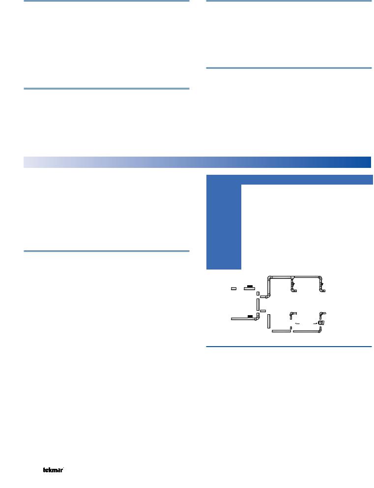
Boiler Control 274
One tN4, Four Stage Boiler & DHW / Setpoint
Do not apply power
1 |
2 |
3 |
4 |
5 |
6 |
tN4 |
Com Out |
Boil |
Com BRet/ |
||
|
– |
+ |
Sup |
|
DHW |
tN4 Boiler Bus
Input |
Outdoor Sensor |
Included |
OR |
0-10 or 2-10 V (dc) |
from EMS |
Input |
Universal |
Sensor |
Included |
|
Output |
|
|
Up to 2 |
|
|
Boiler Pumps |
|
|
OR |
|
Input |
Output |
|
Up to 4 |
||
Universal |
||
On/Off Boilers |
||
Sensor |
||
|
||
Included |
|
Made in Canada by |
Meets Class B: |
||||||||||
tekmar Control Systems Ltd |
Canadian ICES |
||||||||||
tektra 1020-02 |
FCC Part 15 |
||||||||||
Power |
|
115 V ±10% 60 Hz 7 VA, 1150 VA max. |
|||||||||
Relays |
|
230 V (ac) 5 A 1/3 hp |
|
||||||||
Demands |
|
20 to 260 V (ac) 2 VA |
Code |
||||||||
Signal wiring must be rated at least 300 V. |
|||||||||||
Date |
|||||||||||
|
|
|
|
|
|
|
|
|
|
||
7 |
8 |
9 |
10 |
11 12 |
13 14 |
15 16 |
17 18 19 |
20 |
21 22 23 24 25 |
H2050A |
|||||
Relay |
Relay |
Relay |
Relay |
C.A. / |
DHW Prim |
Power |
Boiler |
DHW Com |
Pr. |
||||||
|
|||||||||||||||
|
1 |
|
2 |
3 |
4 |
Alert |
/ P2 P1 |
L |
N |
Demand |
/Setp Dem Dem |
|
|||
|
|
|
|
|
|
|
|
|
|
|
|
|
|
Input |
|
|
|
|
|
|
|
|
|
|
|
|
|
|
|
Flow OR |
|
|
|
|
|
|
|
|
|
|
|
|
|
|
|
C.A. Proof |
|
|
|
|
|
|
|
|
|
|
|
|
|
|
|
Input |
|
|
|
|
|
|
|
|
|
|
|
|
|
|
|
DHW OR |
|
|
|
|
|
|
|
|
|
|
|
|
|
|
|
Setpoint |
|
|
|
|
|
|
|
|
|
|
|
|
|
|
|
Demand |
|
|
|
|
|
|
|
|
|
|
|
|
|
|
|
Signal |
|
|
|
|
|
|
|
|
|
|
|
|
|
|
|
Input |
|
|
|
|
|
|
|
|
|
|
|
|
|
|
|
Boiler |
|
|
|
|
|
|
|
|
|
|
|
|
|
|
|
Demand |
|
|
|
|
|
OR |
|
|
|
|
|
|
|
|
|
Signal |
|
|
|
|
|
|
|
|
|
|
|
|
|
|
|
||
|
|
|
Output |
|
Output |
|
|
Output |
|
Input |
|||||
|
|
|
Combustion |
DHW Pump |
|
Primary |
115 V (ac) |
||||||||
|
|
|
Air Damper |
|
OR |
|
|
Pump |
|
Power Supply |
|||||
|
|
|
OR Alert |
Primary Pump |
|
|
|
|
|
||||||
1 of 44 |
|
|
|
|
|
|
|
© 2012 |
|
274_D - 11/12 |
|||||

How to Use the Data Brochure
This brochure is organized into three main sections. They are: 1) Sequence of Operation,
2)Installation,
3)Control Settings and
4)Testing and Troubleshooting.
The Control Settings section of this brochure describes the various items that are adjusted and displayed by the control. The control functions of each adjustable item are described in the Sequence of Operation.
Table of Contents
User Interface ............................................................... |
2 |
Section M: tekmarNet®4 Communication ............... |
19 |
|
Display and Symbol Description ................................... |
3 |
Installation .................................................................. |
20 |
|
Access Level................................................................. |
4 |
Control Settings ......................................................... |
25 |
|
Sequence of Operation |
4 |
Cleaning the Control .............................................. |
25 |
|
DIP Switch Settings |
25 |
|||
Section A: Boiler Demand |
4 |
|||
VIEW Menu |
27 |
|||
Section B: Outdoor Reset |
4 |
|||
ADJUST Menu |
29 |
|||
Section C: Boiler Operation |
6 |
|||
TIME Menu |
35 |
|||
Section D: Combustion Air and Alert Settings |
8 |
|||
SCHEDULE Menu |
36 |
|||
Section E: Domestic Hot Water Operation |
9 |
|||
MISC Menu |
39 |
|||
Section F: Setpoint Operation |
13 |
|||
Testing the Control |
40 |
|||
Section G: Energy Management System (EMS) |
15 |
|||
Error Messages |
41 |
|||
Section H: Pump Operation |
16 |
|||
Technical Data |
44 |
|||
Section I: Exercising............................................... |
17 |
|||
Section J: Time Clock ............................................ |
17 |
Limited Warranty ....................................................... |
44 |
|
Section K: Setting the Schedule............................. |
18 |
|
|
|
Section L: Boost ..................................................... |
18 |
|
|
User Interface
The control uses a Liquid Crystal Display (LCD) as the method of supplying information. You use the LCD in order to setup and monitor the operation of your system. The control has four push buttons (Menu, Item, ▲, ▼) for selecting and adjusting settings. As you program your control, record your settings in the ADJUST menu table, which is found in the second half of this brochure.
Menu
All of the items displayed by the control are organized into five menus (View, Adjust, Time, Schedule, and Misc). These menus are listed on the top left hand side of the display (Menu Field). To select a menu, use the Menu button. By pressing and releasing the Menu button, the display sequences between the five menus. Once a menu is selected, there will be a group of items that can be viewed within the menu.
Item
The abbreviated name of the selected item will be displayed in the item field of the display. To view the next available item, press and release the Item button. Once you have reached the last available item in a menu, pressing and
releasing the Item button will return the display to the first item in the selected menu.
The items can be quickly scrolled through by holding the Item button and then pressing the ▼ button. To rapidly scroll through the items in the reverse order, hold the Item button and press the ▲ button.
Adjust
To make an adjustment to a setting in the control, begin by selecting the ADJUST, TIME, SCHEDULE or MISC menu using the Menu button. Then select the desired item using the Item button. Finally, use the ▲, and / or ▼ button to make the adjustment.
Additional information can be gained by observing the Status field of the LCD. The status field will indicate which of the control’s outputs are currently active. Most symbols in the status field are only visible when the VIEW menu is selected.
© 2012 |
274_D - 11/12 |
2 of 44 |

Display
Number Field |
Item Field |
Displays the current value |
Displays the current |
of the selected item |
item selected |
Menu Field
Displays the current menu
Status Field
Displays the current status of the control’s inputs, outputs and operation
Buttons
Selects Menus, Items
and adjusts settings
Menu Item
Symbol Description
|
|
PRIMARY PUMP |
|
BOILER PUMP |
|
|
Displays when primary pump 1 or |
|
Displays when the boiler pump 1, 2, 3, |
|
|
primary pump 2 is in operation |
|
or 4 are operating |
|
|
|
|
|
|
|
BOILER |
|
COMBUSTION AIR DAMPER |
|
|
|
||
|
|
Displays which boiler stage is |
|
Displays when the combustion air |
|
|
operating |
|
damper relay is closed |
|
|
|
|
|
|
|
LOCK |
|
SCHEDULE MASTER |
|
|
Displays when adjusting Access level if |
|
Displays when the 274 is a schedule |
|
|
Switch is set to lock. |
|
master |
|
|
|
|
|
|
|
WARNING |
|
WARM WEATHER SHUT DOWN |
|
|
|
Displays when the control is in warm |
|
|
|
Displays when an error exists. |
|
|
|
|
|
weather shut down |
|
|
|
|
|
|
|
|
|
|
|
|
|
COMMUNICATION BUS |
|
MINIMUM & MAXIMUM |
|
|
Displays when tN4 thermostats are |
|
Displays when the boil target or the boil |
|
|
connected. |
|
supply is at a minimum or maximum |
|
|
|
|
|
|
|
DHW PUMP |
Schd Wake |
Schd, Wake, UnOcc, Sleep, Away |
|
|
Displays when the DHW Pump is |
UnOcc Sleep |
Displays the current event of a |
|
|
operating |
Away |
schedule or scene |
|
|
|
|
|
|
|
°F, °C, MINUTES, AM, %, PM, |
|
POINTER |
|
|
HOURS |
|
Displays the control operation as |
|
|
Units of measurement. |
|
indicated by the text |
|
|
|
|
|
3 of 44 |
© 2012 |
274_D - 11/12 |

Access Level
The access level restricts the number of Menus, Items, and Adjustments that can be accessed by the user. The Access Level setting is found in the Miscellaneous (MISC) Menu. Select the appropriate access level for the people who work with the control on a regular basis. There are three Access Level Settings:
•User (USER): Select this access level to limit the highest number of settings available to the end user.
•Installer (INST): Select this access level to limit some of the settings available to the installer. This is the factory default access level.
•Advanced (ADV): Select this access level to have complete access to all of the control settings. In the following menu tables, the appropriate access level needed to view each item is shown in the Access column.
Note: the Lock / Unlock switch on the front of the control must be set to unlock to change the access level.
Sequence of Operation
In order for the control to have a target water temperature there must be a demand. There are three different demands the control can have: boiler demand, DHW demand, and setpoint demand.
Boiler Demand |
Section A |
Once the control receives a boiler demand it calculates a target water temperature based on the characterized heating curve to provide outdoor reset for space heating. The control can receive a boiler demand three different ways:
1.By applying 20-260 V (ac) to the boiler demand terminals (21 & 22) when the DIP switch is set to Demands.
2.From an Energy Management System (EMS) by applying a 0-10 or 2-10 V (dc) signal to terminals 2 & 3 when the DIP switch is set to EMS.
3.From a tN4 device. This requires a tN4 thermostat to be wired to terminals 1 & 2 so that the call for heat can go over the communication bus.
|
21 |
|
22 |
|
|
|
2 |
|
3 |
|
|
|
1 |
|
2 |
|
|
|
|
|
|
|
|
|
|
||||||||
|
Boiler |
|
|
|
Com |
|
Out |
|
|
|
tN4 |
|
Com |
|
||
|
Demand |
|
|
|
– |
|
+ |
|
|
|
|
|
– |
|
||
|
|
|
|
|
|
|
|
|
|
|
|
|
|
|
|
|
|
OR |
OR |
20-260 V (ac) |
0-10 or |
tN4 |
2-10 V (dc) |
||
Demand |
from EMS |
Demand |
Outdoor Reset
In a heating system, the rate of heat supplied to the building must equal the rate at which heat is lost. If the two rates are not equal, the building will either cool off or over heat.
The rate of building heat loss depends mostly on the outdoor temperature. Outdoor Reset allows a hot water heating system to increase the water temperature, adding heat to the building, as the outdoor temperature drops. The rate at which the water temperature is changed as a function of outdoor temperature is defined by the characterized heating curve.
Characterized Heating Curve
A characterized heating curve determines the amount the target water temperature is raised for every 1° drop in outdoor air temperature.
The characterized heating curve takes into account the type of terminal unit that the system is using. Since different types of heating terminal units transfer heat to a space using
Section B
different proportions of radiation, convection and conduction, the supply water temperature must be controlled differently. The control uses the terminal unit setting to vary the supply water temperature to suit the terminal unit being used. This improves the control of the air temperature in the building.
Boiler Characterized Heating Curve
|
|
Boiler |
|
|
|
Design |
Temperatures |
Terminal |
|
|
|
|
|
|
|
Unit |
|
|
Water |
|
Outdoor |
|
|
|
Design |
|
Increasing |
Boiler |
|
|
|
Indoor |
|
|
|
Decreasing Outdoor Temperatures
© 2012 |
274_D - 11/12 |
4 of 44 |

Terminal Unit Setting in Adjust Menu
Select the appropriate terminal unit in the adjust menu. This will change the shape of the characterized heating curve to better match the heat transfer properties of that specific terminal unit.
Hydronic Radiant Floor (HRF1)
A heavy or high mass, hydronic radiant floor system. This type of a hydronic radiant floor is embedded in either a thick concrete or gypsum pour. This heating system has a large thermal mass and is slow acting.
Hydronic Radiant Floor (HRF2)
A light or low mass, hydronic radiant floor system. Most commonly, this type of radiant heating system is attached to the bottom of a wood sub floor, suspended in the joist space, or sandwiched between the subfloor and the surface. This type of radiant system has a relatively low thermal mass and responds faster than a high mass system.
Fancoil (COIL)
A fancoil terminal unit or air handling unit (AHU) consisting of a hydronic heating coil and either a fan or blower. Air is forced across the coil at a constant velocity by the fan or blower and is then delivered into the building space.
Fin–tube Convector (CONV)
A convector terminal unit is made up of a heating element with fins on it. This type of terminal unit relies on the natural convection of air across the heating element to deliver heated air into the space. The amount of natural convection is dependant on the supply water temperature to the heating element and the room air temperature.
Radiator (RAD)
A radiator terminal unit has a large heated surface that is exposed to the room. A radiator provides heat to the room through radiant heat transfer and natural convection.
Baseboard (BASE)
A baseboard terminal unit is similar to a radiator, but has a low profile and is installed at the base of the wall. The proportion of heat transferred by radiation from a baseboard is greater than that from a fin-tube convector.
Boiler Terminal Unit Defaults
When a terminal unit is selected for boiler zones, the control loads default values for the boiler design, boiler maximum supply, and boiler minimum supply temperatures. The factory defaults can be changed to better match the installed system. Locate the Boiler Terminal Unit setting in the Adjust menu.
Terminal Unit |
BOIL DSGN |
BOIL MAX |
BOIL MIN |
High Mass Radiant |
120°F (49°C) |
140°F (60°C) |
OFF |
|
|
|
|
Low Mass Radiant |
140°F (60°C) |
160°F (71°C) |
OFF |
Fancoil |
190°F (88°C) |
210°F (99°C) |
140°F (60°C) |
|
|
|
|
Fin-Tube Convector |
180°F (82°C) |
200°F (93°C) |
140°F (60°C) |
|
|
|
|
Radiator |
160°F (71°C) |
180°F (82°C) |
140°F (60°C) |
|
|
|
|
Baseboard |
150°F (76°C) |
170°F (77°C) |
140°F (60°C) |
|
|
|
|
Room Setting in Adjust Menu
The Room setting is the desired room air temperature, but it is not measuring a room temperature sensor. Instead, the Room setting parallel shifts the heating curve up or down to change the target water temperature. Adjust the Room setting to increase or decrease the amount of heat available to the building. Once the heating curve has been set up properly, the Room setting is the only setting that needs to be adjusted. The default Room setting is 70°F (21°C), and it can be adjusted for both the occupied and unoccupied periods.
|
|
|
|
|
|
|
|
|
5 of 44 |
© 2012 |
274_D - 11/12 |
|
|
|
|
|
|
|
|
|
|||
|
|
|
|
|
|
|
|
|
|||
|
|
|
|
|
|
|
|
|
|||
|
|
|
|
|
|
|
|
|
|||
|
|
|
|
|
|
|
|
|
|||
|
|
|
|
|
|
|
|
|
|||
|
|
|
|
|
|
|
|
|
|||
|
|
|
|
|
|
|
|
|
|||
|
|
|
|
|
|
|
|
|
Outdoor Design Setting in Adjust Menu
The outdoor design temperature is typically the coldest outdoor air temperature of the year. This temperature is used when doing the heat loss calculations for the building and is used to size the heating system equipment. If a cold outdoor design temperature is selected, the supply water temperature rises gradually as the outdoor temperature drops. If a warm outdoor design temperature is selected, the supply water temperature rises rapidly as the outdoor temperature drops.
Boiler Indoor Setting in Adjust Menu
The boiler indoor design temperature is the indoor temperature the heating designer chose while calculating the heat loss for the boiler water heated zones. This temperature is typically 70°F (21.0°C). This setting establishes the beginning of the boiler characterized heating curve.
Boiler Design Setting in Adjust Menu
The boiler design supply temperature is the boiler water temperature required to heat the zones at the outdoor design temperature, or on the typical coldest day of the year.
(Default automatically changes based on terminal unit setting)
Warm Weather Shut Down (WWSD) Setting in Adjust
Menu
Warm Weather Shut Down disables the heating system when the outdoor air temperature rises above this programmable setting. When the control enters into WWSD, the LCD will indicate this in the status field. WWSD is only available when the DIP switch = Demands. The boilers will operate when a Domestic Hot Water (DHW) demand or a Setpoint Demand is present.
Boiler Operation |
Section C |
The 274 is able to operate up to four on/off boilers as a heat source. For proper operation of the boilers, the 274 must be the only control that determines when a boiler is to fire.
*Important note: The boiler operator, or aquastat, remains in the burner circuit and acts as a secondary upper limit on the boiler temperature. The boiler aquastat temperature setting must be adjusted above the 274’s boiler maximum setting in order to prevent short cycling of the burner.
Mode
The 274 control is capable of staging single stage, two stage, three stage and four stage on/off heat sources. As well, in certain modes of operation, the control is capable of controlling the individual boiler pumps. The control has 6 modes of operation based on the type of staging and pump operation that is desired. The following describes the modes of operation.
Mode 1: 4 Single stage boilers and primary pump.
Mode 2: 2 Single stage boilers with individual boiler pumps and primary pump.
|
Relay 1 |
Relay 2 |
Relay3 |
Relay 4 |
|
|
|
|
|
Mode 1 |
Boiler 1 |
Boiler 2 |
Boiler 3 |
Boiler 4 |
|
|
|
|
|
Mode 2 |
Boiler 1 |
Boiler 1 |
Boiler 2 |
Boiler 2 |
|
|
Pump |
|
Pump |
|
|
|
|
|
Mode 3 |
Boiler 1 |
Boiler 1 |
Boiler 2 |
Boiler 2 |
|
Stage 1 |
Stage 2 |
Stage 1 |
Stage 2 |
|
|
|
|
|
Mode 4 |
Boiler 1 |
Boiler 1 |
Boiler 1 |
not used |
|
Stage 1 |
Stage 2 |
Pump |
|
|
|
|
|
|
Mode 5 |
Boiler 1 |
Boiler 1 |
Boiler 1 |
Boiler 1 |
|
Stage 1 |
Stage 2 |
Stage 3 |
Pump |
|
|
|
|
|
Mode 6 |
Boiler 1 |
Boiler 1 |
Boiler 1 |
Boiler 1 |
|
Stage 1 |
Stage 2 |
Stage 3 |
Stage 4 |
|
|
|
|
|
Supply
Sensor
Primary
Pump
Return |
Boiler |
|
Pumps |
||
Sensor |
||
|
Mode 3: 2 Two stage boilers and a primary pump. Mode 4: 1 Two stage boiler and individual pump. Mode 5: 1 Three stage boiler and individual pump. Mode 6: 1 Four stage boiler and primary pump.
Boiler Target Temperature
The boiler target temperature is determined by connected tN4 devices or by a Boiler, DHW or Setpoint demand received by the control. An Energy Management System (EMS) can also give a boiler target. The tN4 devices determine the highest water temperature required and then request this temperature on the tN4 boiler bus. The temperature request creates a Boiler Demand and this is indicated on the display. A DHW demand and a Setpoint demand have temperature settings to which the boilers are operated to meet and are able to override the tN4 bus temperature if required. The control displays the temperature that it is currently trying to maintain as the boiler supply temperature in the View menu. If the control does not presently have a requirement for heat, it does not show a boiler target temperature. Instead, “– – –” is displayed in the LCD.
© 2012 |
274_D - 11/12 |
6 of 44 |
Boiler Minimum Setting in Adjust Menu
The boiler minimum is the lowest temperature that the control is allowed to use as a boiler target temperature. During mild conditions, if the control calculates a boiler target temperature that is below the boiler minimum setting, the boiler target temperature is adjusted to at least the boiler minimum setting. The MIN segment is displayed in the LCD while viewing the boiler supply or target and when the boiler target is boiler minimum and the boiler supply is less than boiler minimum plus 5°F (2.5°C). Set the Boiler Minimum setting to the boiler manufacturer’s recommended temperature.
Boil MIN + 5°F (2.5°C)
 Boiler Di erential
|
|
|
|
|
|
|
e |
|
|
|
|
|
|
|
|
|
|
r |
|
|
Boil MIN |
B |
|
|
|
|
|
|
tu |
|
|
|
o |
|
|
|
|
a |
|
|
|
||
|
|
|
|
r |
|
|
|
|
||
|
i |
|
|
e |
|
|
|
|
||
|
|
l |
|
p |
|
|
|
|
|
|
|
|
|
m |
|
|
|
|
|
|
|
|
|
|
Water Te |
|
|
|
|
|
|
|
 MIN segment on

Boiler Maximum Setting in Adjust Menu
The boiler maximum is the highest temperature that the control is allowed to use as a boiler target temperature. The MAX segment is displayed in the LCD while viewing the boiler supply or target and when the boiler target is boiler maximum and the boiler supply is greater than boiler maximum minus 5°F (2.5°C). Set the boiler maximum setting to the boiler manufacturer’s recommended temperature. At no time does the control operate the boiler above 248°F (120°C).
|
|
|
|
|
e |
|
B |
|
|
|
r |
|
|
|
|
|
u |
|
|
|
o |
|
|
t |
|
|
|
|
a |
|
|
Boil MAX |
||
l |
r |
|
|
|
||
i |
e |
|
|
|
|
|
|
W |
|
|
p |
|
|
|
|
|
|
|
|
a |
|
em |
|
|
|
Boil MAX – 5°F (2.5°C) |
||
|
|
T |
|
|
|
|
||||
|
|
ter |
|
|
|
|
|
Boiler Di erential |
||
|
|
|
|
|
|
|
|
|
||
|
|
|
|
|
|
|
|
|
|
|
|
MAX |
|
|
|
|
MAX |
|
|
|
|
|
segment |
|
|
|
|
segment |
|
|
|
|
|
on |
|
|
|
on |
|||||
Stage Delay Setting in Adjust Menu
The Stage Delay is the minimum time delay between the firing of each stage. After this delay has expired the control can fire the next stage if it is required. This setting can be adjusted manually or set to an automatic setting. When the automatic setting is used, the control determines the best stage delay based on the operation of the system.
Boiler Mass Setting in Adjust Menu (per boiler)
Match the boiler mass setting with the thermal mass characteristics of each boiler. The boiler mass settings also adjusts the inter-stage delay time when operating with an automatic differential.
LO
The LO setting is selected if the boiler that is used has a low thermal mass. This means that the boiler has very small water content and has very little metal in the heat exchanger. A boiler that has a low thermal mass comes up to temperature quite rapidly when fired. This is typical of many copper fin-tube boilers.
The Lo mass setting provides a fast response to the heating system.
MED
The MED setting is selected if the boiler that is used has a medium thermal mass. This means that the boiler either has a large water content and a low metal content or a low water content and a high metal content. This is typical of many modern residential cast iron boilers or steel tube boilers.
The Med mass setting provides a moderate response to the heating system.
HI
The HI setting is selected if the boiler that is used has a high thermal mass. This means that the boiler has both large water content and a large metal content. A boiler that has a high thermal mass is relatively slow in coming up to temperature. This is typical of many commercial cast iron and steel tube boilers.
The Hi mass setting provides a slow response to the heating system.
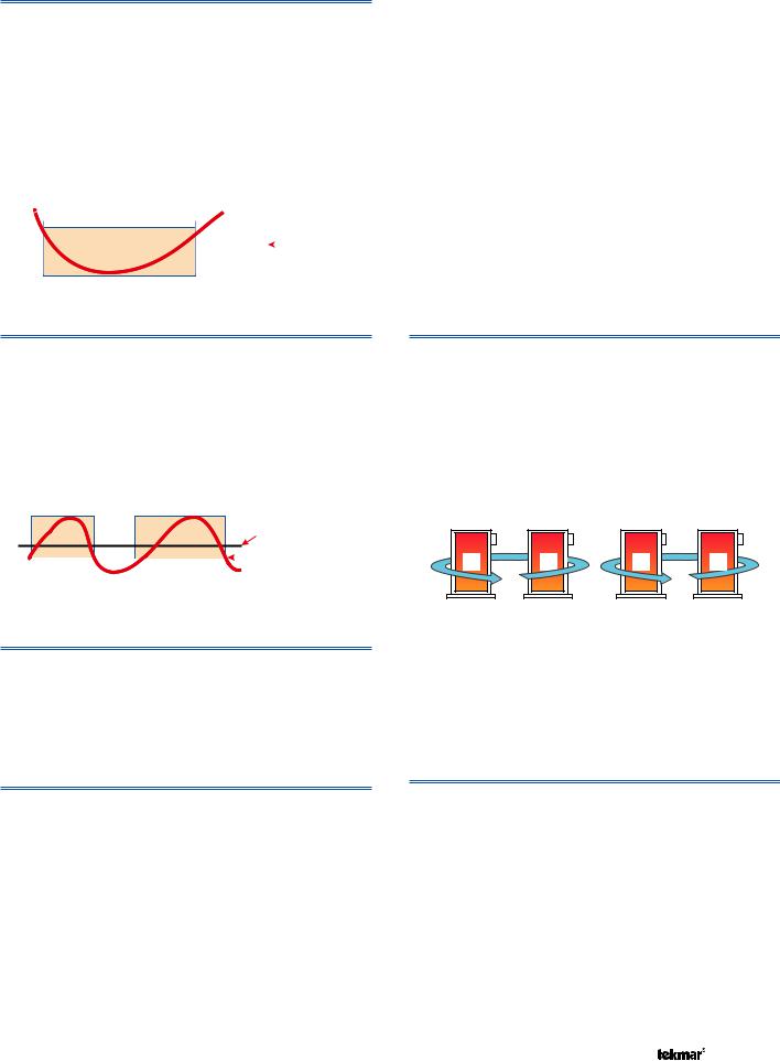
Rotation
The Rotate feature changes the firing order of the boilers whenever one boiler accumulates 48 hours more run time than any other boiler. Rotation will be forced if any boiler accumulates 60 hours more run time. After each rotation, the boiler with the least running hours is the first to fire and the boiler with the most running hours is the last to fire. This function ensures that all of the boilers receive equal amounts of use. When the Rotate / Off DIP switch is set to the Off position, the firing sequence always begins with lowest boiler to the highest boiler.
1 |
2 |
2 |
1 |
720 hours |
672 hours |
672 hours |
720 hours |
To reset the rotation sequence (without regard to historical running hours), toggle the Rotation DIP Switch Off for 3 seconds and on again. Note that the running hours (see Run Time) in the View menu also need to be reset if you want the rotation sequence and running hours display to be synchronized.
Fixed Last
In some applications, it may be desirable to have the last boiler fire last at all times while the firing sequence of the remaining boilers is changed using Equal Run Time Rotation. This configuration is typical of installations where the boiler plant includes higher efficient boilers and a single less efficient boiler. The lesser efficient boiler is only desired to be operated when all other boilers in the plant are on and the load cannot be satisfied. This rotation option is selected by setting the Fixed Last / Off DIP switch to Fixed Last. With a fixed last rotation, the last boiler is the last to stage on and the first to stage off.
7 of 44 |
© 2012 |
274_D - 11/12 |

Fixed Lead & First On / First Off
In some applications, it may be desirable to have the first boiler fire first at all times while the firing sequence of the remaining boilers is changed using Equal Run Time Rotation. This rotation option is selected by setting the Fixed Lead / Off DIP switch to the Fixed Lead position.
When using the Fixed Lead rotation option, a selection must be made between First On / Last Off and First On / First Off using the DIP switch.
When First On / First Off is selected, the lead boiler is always staged on first and staged off first. This configuration is typical of installations where the boiler plant includes similar boilers but the first boiler is required to be the first to fire in order to establish sufficient draft for venting.
Fixed Lead & First On / Last Off
When First On / Last Off is selected, the lead boiler is always staged on first and staged off last. This configuration is typical of installations where the boiler plant includes a single higher efficient boiler with lesser efficient boilers. The lead boiler is the high efficiency boiler, therefore it is the last boiler to be sequenced off.
Boiler Run Time in View Menu
The running time of each boiler is logged in the view menu. To reset the running time, select the appropriate Boiler Run Time in the View menu and press and hold the Up and Down buttons simultaneously until CLR is displayed.
Boiler Differential Setting in Adjust Menu
An On/Off heat source must be operated with a differential in order to prevent short cycling. The boiler differential can be fixed or automatically determined by the control. The Auto Differential setting balances the amount of temperature swing in the boiler supply temperature with boiler on times, off times, and cycle times. This reduces potential short cycling during light load conditions.
Combustion Air and Alert Settings
Relay Setting in Adjust Menu (C.A. Damper / Alert)
The control includes an auxiliary relay that can be used either for a combustion damper/venting device or an Alert. Selection is made through the Relay item in the Adjust menu.
Manual Differential
Di erential = 10°F (6°C)
165°F (74°C) |
|
Target + 1/2 Di erential |
160°F (71°C) |
|
Target |
155°F (68°C) |
|
Target – 1/2 Di erential |
Boiler |
Boiler |
|
On |
On |
|
Automatic Differential |
|
|
Off |
|
|
Differential |
On |
Load |
|
||
|
Heating |
|
|
|
|
Time |
|
|
Boiler Staging Mode - Lo/Hi or Lo/Lo in Adjust Menu
When using multi-stage boilers, a selection must be made regarding the staging order of the boiler(s). This adjustment is made in the ADJUST menu of the control.
Lo/Hi: If the Lo/Hi staging option is selected the control stages in sequence all of the stages in a single boiler. Once all of the stages are turned on, the control then stages in sequence all of the stages of the next boiler in the rotation sequence.
Lo/Lo: If the Lo/Lo staging option is selected, the control stages all of the Lo stage outputs in all of the boilers first. Once all of the boilers are operating on their Lo stages, the control then operates the second stage in each boiler in the same order.
Boiler Fire Delay Setting in Adjust Menu
(per boiler)
The Boiler Fire Delay sets the time it takes for the boiler to generate flame from the time the boiler turns on.
Boiler Contact Closed 
Fire Delay
Burner On
Time
Section D
Alert
When the Relay is set to Alert, terminals 15 and 16 close whenever a control or sensor error is detected, or when a warning or limiting condition is detected. When the alert contact closes, refer to the Error Messages section of this brochure to determine the cause of the alert and how to clear the error.
© 2012 |
274_D - 11/12 |
8 of 44 |

Boiler Alarm
For the Boiler Alarm item to appear in the Adjust menu, the Relay must be set to Alert. If no temperature increase is detected at the boiler supply sensor within this delay period, the Alert relay will close and the control will display the Boiler Alarm error message. All boilers continue to operate if this error is present. To clear the error, press and hold the up and down buttons simultaneously for 5 seconds while viewing the error message in the View menu.
Combustion Air (C.A.) Damper
When the Relay is set to Damper, terminals 15 and 16 operate a combustion air damper / fan motor or power vent motor. The Relay closes once a demand is received and the control has determined that one or more boilers need to be turned on.
Combustion Air Proof Demand Setting in Adjust Menu
The proof demand can be used to prove a combustion air or venting device if set to C.A. Boiler operation cannot occur until the proof demand is present. If the proof demand is lost during operation, the boiler plant is sequenced off.
Combustion Air Proof Demand Delay Setting in Adjust
Menu
The control includes a time delay that is associated with the proof demand feature in order to determine if the proof device is functional. Once the C.A. relay closes, the control allows for this delay to receive the proof demand. If the proof demand is not received within the delay time, the control will display an error message.
Combustion Air Damper Delay Setting in Adjust Menu
If the Proof Demand function is set to F P (flow proof) or OFF, boiler sequencing only occurs once a user adjustable time delay elapses.
Combustion Air Post Purge
There is a fixed 15 second post purge of the C.A. relay after the last boiler has turned off, or demand is removed. If there is a heat demand still present once the last boiler has turned off, the control can look at the error and determine if sequencing is to occur in a “short” period of time. If the control does anticipate staging, the C.A. relay will remain on. Otherwise, the C.A. relay will be turned off once the 15 second post purge elapses.
Combustion Air Proof Demand Test
The control includes a C.A. proof demand test in order to determine if the proving device has failed. If the C.A. damper contacts are opened, the flow proof demand should not be present after 4 minutes. If the flow proof demand remains, the control will display an error message.
Domestic Hot Water Operation |
Section E |
DHW operation is only available when the Pump Sequencer DIP Switch is set to Off.
DHW Demand
DHW Demands come from one of three sources: an external aquastat, a DHW tank sensor, or a tN4 DHW control.
Once the control detects a DHW Demand, the DHW Demand segment is displayed in the LCD. If an External Powered DHW Demand is applied while the DHW sensor is enabled in the 274, an error message is generated and both demands are ignored.
A DHW demand from a tN4 Setpoint Control can coexist with another DHW demand without generating an error message. The 274 will then use the higher of the two targets.
Powered DHW Demand
The control registers a DHW Demand when a voltage between 20 and 260 V (ac) is applied across the DHW Demand terminals 23 and 24. An aquastat or setpoint control is used to switch the DHW Demand circuit. Program a DHW Exchange temperature for the Occupied and UnOccupied events in the Adjust Menu.
• DHW Sensor must be set to Off.
DHW Sensor
The control can register a DHW Demand when A DHW Sensor is wired to terminals 5 and 6. Once the DHW Sensor drops 1/2 of the DHW Differential setting below the DHW Setpoint, the control registers a DHW Demand. Program a DHW Tank temperature for the Occupied and UnOccupied events in the Adjust Menu.
•The DHW Sensor must be set to On. There cannot be an externally powered DHW demand when using a DHW sensor.
tN4 Setpoint Control in DHW Mode
The control can register a DHW Demand when a tN4 Setpoint Control in DHW Mode is wired to terminals 1 and 2. The DHW Demand is sent over the tN4 communication bus when the Setpoint Control calls for heat. Program a DHW tank temperature for the Occupied and UnOccupied events and the desired supply water temperature required on the tN4 bus in the Adjust Menu of the tN4 Setpoint Control.
9 of 44 |
© 2012 |
274_D - 11/12 |
DHW Differential Setting in Adjust Menu
Due to large differences between the heating load and the DHW load, a separate DHW differential should be used whenever a DHW Demand is present. This will improve staging and boiler cycling. When using a DHW Sensor, a DHW Demand is registered when the DHW sensor drops 1/2 of the DHW Differential setting below the DHW setting. The DHW Demand is satisfied once the DHW Sensor rises 1/2 of the DHW Differential setting above the DHW setting.
OFF
|
DHW |
|
Differential |
ON |
DHW Target |
|
Boiler Target Temperature during a DHW Demand
If a Powered DHW Demand is present, the boilers are operated to maintain the DHW Exchange temperature. If a DHW sensor demand is present, the boilers are operated to maintain a temperature 40°F above the DHW tank temperature. If a tN4 demand is present, the primary pump is turned on according to the device’s reported requirements and the boilers are operated to maintain the devices requested target on the bus. The DHW Demand overrides the boiler reset target temperature, except when the boiler reset target is higher than the DHW target. Regardless of DHW settings and requested targets, the boilers will maintain a supply temperature no higher than the Boil MAX setting.
DHW During UnOccupied
When using a Powered DHW Demand, the control has a DHW Exchange UnOccupied setting that allows the installer to select On or Off. When set to On, and the control receives a DHW Demand during an UnOccupied or Sleep period, the control continues operation of the DHW system as it would during the Occupied and Wake periods. When set to Off, the control will ignore a DHW Demand for the duration of the UnOccupied and Sleep periods.
When using a DHW Sensor, a second DHW temperature setting is available for the UnOccupied or Sleep period.
DIP Switch must be set to Setback to view UnOccupied items.
During the Away Scene, DHW demands are ignored.
DHW Mode Setting in the Adjust Menu
The control has six different DHW Modes that affect pump operation. The required DHW Mode setting will depend on the piping arrangement of the DHW tank and whether or not priority for DHW is necessary. DHW Priority stops or limits the delivery of heat to the building heating system while the DHW tank calls for heat. This allows for quick recovery of the DHW tank.
Mode OFF / No DHW Generation
All DHW demands are ignored. If this mode is selected while DHW generation is underway, all DHW operation stops.
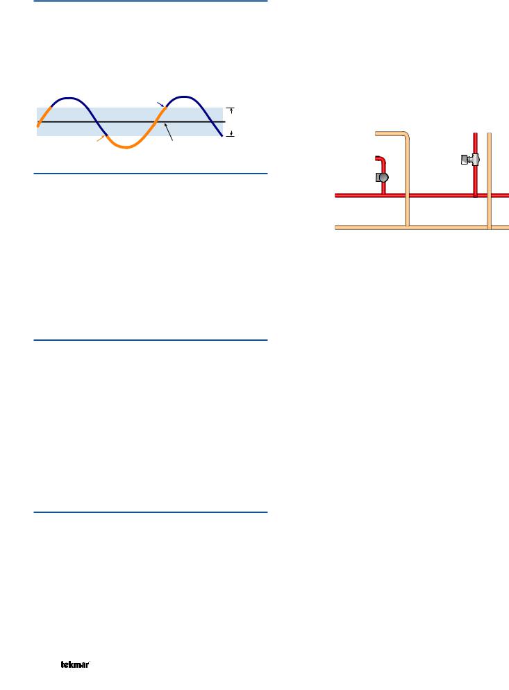
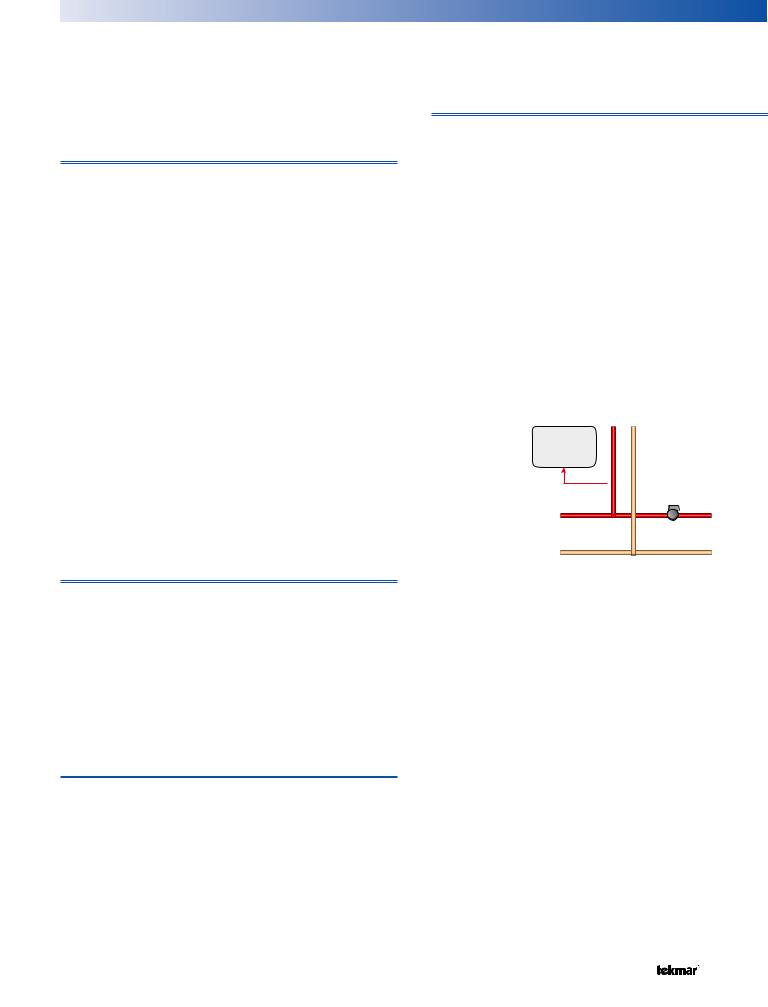
Mode 1 - DHW in Parallel with No Priority
When a valid DHW Demand is present, the DHW relay (terminal 17) turns on. The primary pump can operate when a Boiler Demand is present. It is assumed that the DHW pump will provide adequate flow through the heat exchanger and the boiler. Heating zones are unaffected by DHW operation.
Mode = 1
DHW
Pump
Primary
Pump
Mode 2 - DHW in Parallel with Priority
When a valid DHW Demand is present, the DHW relay (terminal 17) turns on. The primary pump can operate when a Boiler Demand is present. If the boilers are unable to maintain the boiler target temperature, space heating zones are shut off sequentially using tN4 communication in order to provide priority to the DHW tank. For non-tN4 systems, the primary pump shuts off to provide priority. It is assumed that the DHW pump will provide adequate flow through the heat exchanger and the boiler.
Mode = 2
OFF 


DHW
Pump
Primary
Pump
© 2012 |
274_D - 11/12 |
10 of 44 |
Mode 3 - DHW in Primary/Secondary with No Priority
When a valid DHW Demand is present, the DHW relay (terminal 17) and Primary Pump relay (terminal 18) turn on. Heating zones are unaffected by DHW operation. This mode can be used if the DHW tank is piped in parallel and a DHW valve is installed (need to use an external relay to power the valve with 24 V (ac) since the DHW pump output is a 120 V (ac) powered output).
Mode = 3
DHW
Pump
Primary
Pump
Mode 4 - DHW in Primary/Secondary with Priority
When a valid DHW Demand is present, the DHW relay (terminal 17) and Primary Pump relay (terminal 18) turn on. If the boilers are unable to maintain the boiler target temperature, space heating zones are shut off sequentially using tN4 communication in order to provide priority to the DHW tank.
Mode = 4
OFF 


DHW
Pump
Primary
Pump
Mode 5 - DHW in Parallel / Last Boiler with Priority
When a valid DHW Demand is present, the DHW relay (terminal 17) turns on and boiler pump 4 turns off. The control uses the DHW Exchange Supply Sensor in order to measure the boiler supply temperature supplied to the indirect tank. There are two boiler target temperatures, one for the heating system (BOIL TARGET) and one for the indirect DHW system (BOIL DHW TARGET). In this mode, the DHW Demand can only be provided from an External Powered Demand or tN4 Setpoint Control in DHW mode.
•All boilers are used for space heating requirements
•Boiler 2 is used for DHW when there is a DHW demand
•The dedicated DHW boiler is always boiler 2 (relay 3), even if there are less than 4 boilers.
•If boiler 2 is disabled and mode 5 is selected then the dedicated DHW boiler (boiler 2) will not operate.
•This DHW mode is only available when control is in Mode = 2
Mode = 5
DHW Exchange
Supply Sensor
DHW Pump
ON
|
Boiler |
OFF |
Supply |
Sensor |
|
|
Primary |
|
Pump |
Mode 6 – Dedicated DHW
When a valid DHW Demand is present from the DHW Sensor, the primary pump relay turns on. The DHW Relay in this mode is used as the DHW recirculation pump and operates continuously in the Occupied period and cycles with the primary pump in the UnOccupied period. The boiler plant is sequenced based only on the DHW Sensor.
•All boilers are used for DHW requirements
•Requires DHW demand from DHW sensor
•DHW Pump Relay is used for DHW recirculation pump
•Boiler Supply Sensor Not Required
Mode = 6
On/ |
On/ |
Off |
Off |
 DHW Sensor
Recirculation
Pump
11 of 44 |
© 2012 |
274_D - 11/12 |
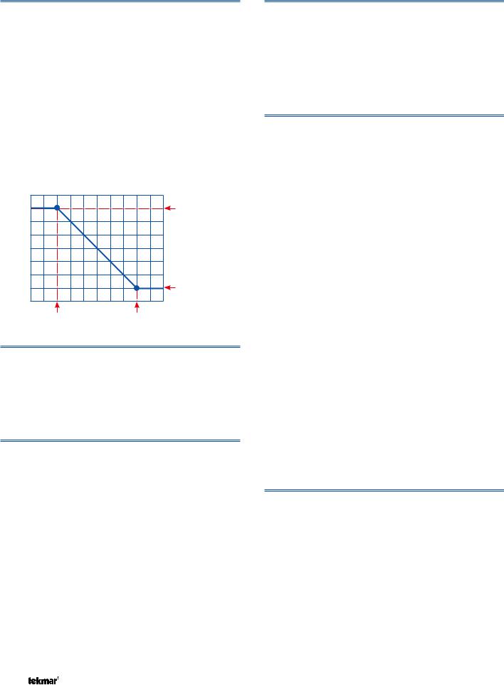
DHW Priority Override Setting in Adjust Menu
DHW Priority Override applies to DHW MODE 2 and 4, as well as Mode 5 if there is a tN4 device with DHW. It prevents the building from cooling off too much or the possibility of a potential freeze up during DHW priority.
When set to auto, the priority time is calculated based on outdoor temperature. At or below the design outdoor temperature, 15 minutes are allowed for DHW priority. At or above 70°F, 2 hours are allowed for DHW priority. The time allowed for DHW priority varies linearly between the above two points. There is a manual setting also available in the adjust menu.
The priority timer does not start timing until priority is selected and both a DHW Demand and a Boiler Demand exist together. Once the allowed time for priority has elapsed, the control overrides the DHW priority and resumes space heating.
Automatic Priority Override
|
2 hours |
|
15 mins |
70°F (21°C) |
Design Temperature |
Conditional DHW Priority
If the boiler supply temperature is maintained at or above the required temperature during DHW generation, this indicates that the boilers have enough capacity for DHW and possibly heating as well. As long as the boiler supply temperature is maintained near the target, DHW and heating occurs simultaneously.
DHW Post Purge
After the DHW Demand is removed, the control performs a purge. The control shuts off the boilers and continues to operate the DHW Pump and the primary pump if applicable. This purges the residual heat from the boilers into the DHW tank. The control continues this purge until one of the following occurs:
1.A Boiler Demand is detected
2.The boiler supply drops 20°F (11°C) below the DHW target temperature
3.The DHW tank temperature rises above the DHW setpoint plus 1/2 DHW Differential
4.Two minutes elapse
DHW Mixing Purge
After DHW operation, the boiler is extremely hot. At the same time, the heating zones may have cooled off considerably after being off for a period of time. When restarting the heating system after a DHW demand with priority, the control shuts off the boiler and continues to operate the DHW pump while the primary pump is turned on. This allows some of the DHW return water to mix with the cool return water from the zones and temper the boiler return water.
DHW with Low Temperature Boilers
If DHW heating is to be incorporated into a low temperature system such as a radiant floor heating system, a mixing device is often installed to isolate the high DHW supply temperature from the lower system temperature. If a mixing device is not installed, high temperature water could be supplied to the low temperature system while trying to satisfy the DHW demand. This may result in damage to the low temperature heating system.
The control is capable of providing DHW heating in such a system while minimizing the chance that the temperature in the heating system exceeds the design supply water temperature. In order to do this, the following must be true:
•tN4 Present
•DHW MODE 2 or 4
•Boil MIN OFF
On a call for DHW, the control provides DHW priority by sending a message on the boiler temperature bus to the tN4 thermostats to shut off the heating zones for a period of time. The length of time is based on the outdoor air temperature as described in the DHW Priority Override section. However, if the DHW Demand is not satisfied within the allotted time, the boiler shuts off and the heat of the boiler is purged into the DHW tank. A DHW mixing purge occurs in order to reduce the boiler water temperature and once the boiler supply temperature is sufficiently reduced, the DHW Pump contact shuts off. The heating system zones are allowed to turn on for a period of time to prevent the building from cooling off. After a period of heating, and if the DHW Demand is still present, the control shuts off the heating system and provides heat to the DHW tank once again.
DHW Boilers Setting in Adjust Menu
Select the number of boilers to use for DHW generation.
© 2012 |
274_D - 11/12 |
12 of 44 |
Setpoint Operation |
Section F |
Setpoint operation is only available when DHW Mode is set to Off.
The control can operate to satisfy the requirements of a setpoint load in addition to a space heating load. A setpoint load overrides the current outdoor reset temperature in order to provide heat to the setpoint load.
Setpoint Demand
Setpoint Demands come from one of two sources: a Powered Setpoint Demand, or a tN4 Setpoint Control.
Powered Setpoint Demand
The control registers a Setpoint Demand when a voltage between 20 and 260 V (ac) is applied across the Setpoint Demand terminals 23 and 24. An aquastat or setpoint control is used to switch the Setpoint Demand circuit. Program a Setpoint target for the Occupied and UnOccupied events in the Adjust Menu.
• DHW Mode must be set to Off.
tN4 Setpoint Control
The control can register a Setpoint Demand when a tN4 Setpoint Control is wired to terminals 1 and 2. The Setpoint Demand is sent over the tN4 communication bus when the Setpoint Control calls for heat. Program a Setpoint temperature for the Occupied and UnOccupied events and the desired supply water temperature required on the tN4 bus in the Adjust Menu of the tN4 Setpoint Control.
• DHW Mode must be set to Off.
A demand from a tN4 Setpoint Control can coexist with another setpoint demand without generating an error message. The 274 will then use the higher of the two targets.
Boiler Target Temperature during a Setpoint Demand
If a Powered Setpoint Demand is present, the boilers are operated to maintain the Setpoint target. If a tN4 demand is present, the primary pump is turned on according to the device’s reported requirements and the boilers are operated to maintain the devices requested target on the bus. The Setpoint Demand overrides the boiler reset target temperature, except when the boiler reset target is higher than the Setpoint target. Regardless of Setpoint settings and requested targets, the boilers will maintain a supply temperature no higher than the Boil MAX setting.
Setpoint During UnOccupied
When using a Powered Setpoint Demand, the control has a Setpoint UnOccupied setting that allows the installer to select On or Off. When set to On, and the control receives a Setpoint Demand during an UnOccupied or Sleep period, the control continues operation of the Setpoint system as it would during the Occupied and Wake periods. When set to Off, the control will ignore a Setpoint Demand for the duration of the UnOccupied and Sleep periods.
DIP Switch must be set to Setback to view UnOccupied items.
During the Away Scene, Setpoint demands are ignored.
Setpoint Mode Setting in the Adjust Menu
The control has four different Setpoint Modes that affect pump operation. The required Setpoint Mode setting will depend on the piping arrangement and whether or not priority is necessary. Setpoint Priority stops or limits the delivery of heat to the building heating system while the Setpoint load calls for heat. This allows for quick recovery of the Setpoint load.
Mode OFF - No Setpoint Operation
All Setpoint demands are ignored. If this mode is selected while Setpoint operation is underway, all Setpoint operation ceases.
Mode 1 - Setpoint in Parallel with No Priority
Whenever a Setpoint Demand is present, the boilers are operated to maintain the setpoint target. The primary pump does not turn on, but may operate based on a Boiler Demand. It is assumed that the Setpoint pump will provide adequate flow through the heat exchanger and the boiler.
Mode = 1
Setpoint
Primary
Pump
Mode 2 - Setpoint in Parallel with Priority
When a Setpoint Demand is present, the boilers are operated to maintain the setpoint target. The primary pump can operate when a Boiler Demand is present. If the boilers are unable to maintain the boiler target temperature, space heating zones are shut off sequentially using tN4 communication in order to provide priority to the Setpoint Load. For non-tN4 systems, the primary pump shuts off to provide priority. It is assumed that the Setpoint pump will provide adequate flow through the heat exchanger and the boiler.
Mode = 2
Setpoint
OFF 


Primary
Pump
13 of 44 |
© 2012 |
274_D - 11/12 |

Mode 3 - Setpoint in Primary/Secondary with No Priority
Whenever a Setpoint Demand is present, the primary pump is turned on and the boilers are operated to maintain the setpoint target.
Mode = 3
Setpoint
Primary
Pump
Mode 4 - Setpoint in Primary/Secondary with Priority
Whenever a Setpoint Demand is present, the primary pump is turned on and the boilers are operated to maintain the setpoint target. Space heating zones will be shut off if the boilers are unable to maintain the boiler target temperature.
Mode = 4
Setpoint
OFF 


Primary
Pump
Setpoint Priority Override Setting in Adjust Menu
Setpoint Priority Override applies to SETPOINT MODE 2 and MODE 4. To prevent the building from cooling off too much or the possibility of a potential freeze up during setpoint priority, the control limits the amount of time for setpoint priority.
When set to auto, the priority time is calculated based on outdoor temperature. At or below the design outdoor temperature, 15 minutes are allowed for Setpoint priority. At or above 70°F, 2 hours are allowed for Setpoint priority. The time allowed for Setpoint priority varies linearly between the above two points. There is a manual setting also available in the adjust menu.
The priority timer does not start timing until priority is selected and both a Setpoint Demand and a Boiler Demand exist together. Once the allowed time for priority has elapsed, the control overrides the Setpoint priority and resumes space heating.
Automatic Priority Override
|
2 hours |
|
15 mins |
70°F (21°C) |
Design Temperature |
Conditional DHW Priority
If the boiler supply temperature is maintained at or above the required temperature during setpoint generation, this indicates that the boiler has enough capacity for setpoint and possibly heating as well. As long as the boiler target temperature is maintained, setpoint and heating occur at the same time.
Setpoint Post Purge
After a tN4 Setpoint Demand is removed, the control performs a purge. The control shuts off the boilers and continues to operate the Setpoint Pump and the primary pump if applicable. This purges the residual heat from the boilers into the Setpoint load. The control continues this purge until one of the following occurs:
1.A Boiler Demand is detected
2.The boiler supply drops 20°F (11°C) below the Setpoint target temperature
3.Two minutes elapse
© 2012 |
274_D - 11/12 |
14 of 44 |
 Loading...