


 Loading...
- Data Brochure |
D 368 |
Zone Control 368 |
09/96 |
|
|
|
|
|
|
|
|
|
|
Occupied |
Power |
|
UnOccupied |
Heat Required |
Optimum Start / Stop |
|
|
|
|
|
|
Timer Active |
|
24 hr. Timer |
|
70°F |
|
System Pump |
• Dial the desired duration |
|
12 hrs. |
|
(21°C) |
1 |
Zone 1 Lo stage |
6 |
18 |
|
|
|||
of the UnOccupied period. |
|
|
2 |
Zone 2 Hi stage |
||
• Press start button at the time of day |
|
|
|
|||
you want the UnOcc. period to begin. |
|
|
|
|
|
|
Timer Active light turns on. |
|
|
|
|
3 |
Zone 3 Lo stage |
|
0 |
24 |
40 |
100 |
|
|
|
UnOccupied |
(4) |
(38) |
4 |
Zone 4 Hi stage |
|
|
|
Duration |
UnOccupied |
|
|
|
Start |
0 = always Occupied |
|
|
|
|
|
|
24 = always UnOccupied |
|
|
|
|
|
Zone Control 368
N R T L / C
|
One & Two Stage |
LR 58223 |
|
|
|
|
|
|
|
|
|
|
|
|
|
|
|
|
|
|
|
|
|
|
|
|
|
|
|
|
|
|
|
|
|
|
|
|
The Zone Control 368 is a microprocessor-based energy management control that uses PID logic to control the temperature in up to 4 heating zones. Multiple zone controls can be connected together for additional zones of heating. Either single stage or two stage zones can be provided by the control. The 368 is primarily designed for use with the tekmar House Controls. When connected to a House Control, the 368 provides indoor temperature feedback that adjusts the supply water temperature in order to satisfy the zone with the highest heat load. The 368 also coordinates the zoning operation in order to minimize boiler short cycling and allow boiler purging between cycles. The 368 has a built in night setback timer and an Optimum Start / Stop feature that allows the control to reheat the zones before the end of the setback period.
Control Strategy . . . . . . . . . . . . . . . . |
pg. 2 |
Testing the Control |
. . . pg. 9 |
Sequence of Operation . . . . . . . . . . |
pg. 3 |
Error Messages . . . |
. . . pg. 11 |
Installation . . . . . . . . . . . . . . . . . . . . |
pg. 6 |
Technical Data . . . . |
. . . pg. 12 |
Settings . . . . . . . . . . . . . . . . . . . . . . . |
pg. 8 |
Limited Warranty . . . |
. . pg. 12 |

 Occupied

 UnOccupied

 Optimum Start / Stop
|
Timer Active |
24 hr. Timer |
|
|
12 hrs. |
• Dial the desired duration of the |
6 |
18 |
UnOccupied period. |
||
• Press start button at the time of day |
|
|
you want the UnOcc. period to begin. |
|
|
Timer Active light turns on. |
|
|
|
0 |
24 |
UnOccupied
Duration
Start |
0 = always Occupied |
|
24 = always UnOccupied |
70°F
(21°C)
40 |
100 |
(4) |
(38) |
UnOccupied |
|

 Power
Power

 Heat Required

 System Pump
1Zone 1 / Lo stage
2Zone 2 / Hi stage
3Zone 3 / Lo stage 4 Zone 4 / Hi stage
Thermal Motor
Optimum Start
Occ/UnOcc
Zone 1 2 3 4
Occ. only Off
Test
|
|
Made in Canada by |
Sep 96 |
|
|
|
|
tekmar Control Systems Ltd. |
31000266 |
|
|
Zone Control 368 |
R |
|
|
||
N R T L / C |
Power |
120 V 50/60 Hz 5 VA |
|
|
|
One & Two Stage |
Pump Relay |
120 V (ac) 6 A 1/3 hp, pilot duty 240 VA |
|||
LR 58223 |
Zone Relays |
120 V (ac) 6 A 1/3 hp, pilot duty 240 VA |
|||
|
Do not apply power here |
Caution: Signal wiring must be rated at least 300V |
|||
1 |
2 |
3 |
4 |
5 |
6 |
7 |
8 |
9 |
10 11 12 13 |
14 |
15 16 17 18 19 20 |
||||||||
System |
Power |
Com RTU RTU Com RTU RTU UnO |
Zo |
Com |
Zo |
Com |
|
|
Com |
|
|
||||||||
Pmp Pmp |
N |
L |
Sen |
1 |
2 |
Sen |
3 |
4 |
Sw |
Out |
Sen |
In |
1-2 |
1 |
2 |
3-4 |
3 |
4 |
|
Output |
|
|
|
|
|
|
|
|
|
|
|
|
|
|
|
|
|
|
|
System |
|
|
|
|
|
|
|
|
|
|
|
|
|
|
|
|
|
|
|
Pump |
|
|
|
|
|
|
|
|
|
|
|
|
|
|
|
|
|
|
|
Input |
|
|
|
|
|
|
|
|
|
|
|
|
|
|
|
|
|
|
|
120 V (ac) |
|
|
|
|
|
|
|
|
|
|
|
|
|
|
|
|
|
|
|
Power |
|
|
|
|
|
|
|
|
|
|
|
|
|
|
|
|
|
|
|
Supply |
|
|
|
|
|
|
|
|
|
|
|
|
|
|
|
|
|
|
|
Input tekmar RTUs or Indoor Sensors
Input |
Output |
Input |
tekmar |
tekmar Reset |
tekmar Zone |
Timer |
Control |
Control |
H1144 1
 M
M
 M
M
 M
M
Outputs
Zone Valves or
Zone Pumps
 M
M
Outputs
Zone Valves or
Zone Pumps
Control Strategy
ZONING OPERATION
In a multiple zone heating system, the zones may have different internal heat gains, heat losses or different temperature settings. Each zone must therefore have individual temperature control. For maximum comfort, the heat should be continuously supplied to the zone at the same rate the zone is losing heat. The most accurate method of accomplishing this is by outdoor reset; however, it is not normally economical to modulate the supply water temperature to every zone.
Outdoor reset can be combined with zoning for a more cost effective solution. Through indoor sensors, a zone control can provide indoor temperature feedback to the outdoor reset control. The outdoor reset control will then adjust the supply water temperature to satisfy the zone with the highest water temperature requirement. Heat to the remaining zones will be cycled on and off by the zone control using zone valves or pumps. Since the heat is cycled on and off, accurate PID control logic should be provided to maintain a stable indoor temperature.
PID Zoning Logic ¾¾¾¾¾¾¾¾¾¾¾¾¾¾¾¾¾¾¾¾¾¾¾¾¾¾¾
90% |
85% |
100% |
time on |
time on |
time on |
M |
M |
M |
Heat
Source
Proportional (P)
In order to prevent indoor temperature swings, the heat supplied to each zone must be proportional to the heat required by the zone. Proportional control logic can be accomplished by pulse width modulation (PWM). A typical PWM system has a fixed operating cycle. During this operating cycle, the on time of the zone relay is varied based on the difference between the desired zone temperature and the actual zone temperature. As the zone temperature drops, the relay on time increases and as the zone temperature rises, the relay on time decreases.
no heat |
|
|
72 °F |
10 minutes |
5 minutes |
(22°C) |
||
on |
|
70 °F |
|
(22°C) |
|
|
|
|
|
|
68 °F |
15 minutes |
15 minutes |
(20°C) |
Integral (I)
Controls that are strictly proportional suffer from a problem of offset. The amount of heat
supplied to the zone depends on how far the space temperature is below the desired setpoint. This implies that as the heating load increases, the average room temperature droops. On the coldest day of the year, the most heat is required and therefore the room
temperature must be coldest.
In order to overcome this offset, integral control logic is used. Only digital controls can provide integral control logic due to the lengthy response time of buildings. Integral control logic is based on time. The longer the room temperature is below the desired setpoint, the more heat is supplied to the room. With integral control logic, full heat can be supplied to the room on the coldest day of the year without requiring that the room be cold.
Derivative (D)
In order to speed up the control’s response to quick changes in the heating load, derivative control logic is required. However, sudden room temperature changes, for example from an open door or window, should be ignored by an intelligent control.
P + I + D = PID
If proportional, integral and derivative (PID) control logic are combined, the control is more able to prevent excessive temperature swings and provide a stable room temperature under all conditions. It not only takes into account how much the room temperature has drooped, but also how long there has been a droop and how fast the temperature is changing.
Zone Load Staggering ¾¾¾¾¾¾¾¾¾¾¾¾¾¾¾¾¾¾¾¾¾¾¾¾
In a multiple zone system, there can be sudden load changes on the boiler and system due to multiple zones turning on or off. These sudden load changes often lead to boiler short cycling and unnecessary mechanical stresses. The operation of the system can be improved by staggering the starting points of each zone relay within the operating cycle. Staggering of the zones maintains a relatively constant system flow rate which improves boiler operation. Controlled staggering can also minimize boiler running time and improve system efficiency when only a few zones are needed for short periods.
On |
Zone 1 |
Zone 2 |
On |
On |
Zone 3 |
Zone 4 |
On |
Post Purge (Boiler off, Pump on)
Zone Post Purge ¾¾¾¾¾¾¾¾¾¾¾¾¾¾¾¾¾¾¾¾¾¾¾¾¾¾¾¾¾¾¾¾¾¾¾¾¾¾¾¾¾¾¾¾
Before the last zone is turned off in a heating cycle, the boiler is turned off but the zone continues to draw heat from the boiler. This post purge of the boiler reduces stand-by losses and reduces overall energy consumption.
UNOCCUPIED (NIGHT SETBACK)
During the night, or at times when people are not within the building, energy can be saved by lowering the building temperature for an UnOccupied (Night Setback) period.
Due to the large thermal mass of buildings, it takes a long time for the indoor space temperature to significantly change whenever the heating system is turned on or off. The building heat up or cool down time is further increased when high mass heating systems are used (e.g. radiant floors). In most cases night setback cannot be used with these systems due to the long recovery time required in the morning. A typical system is demonstrated in the diagram on page 3.
2
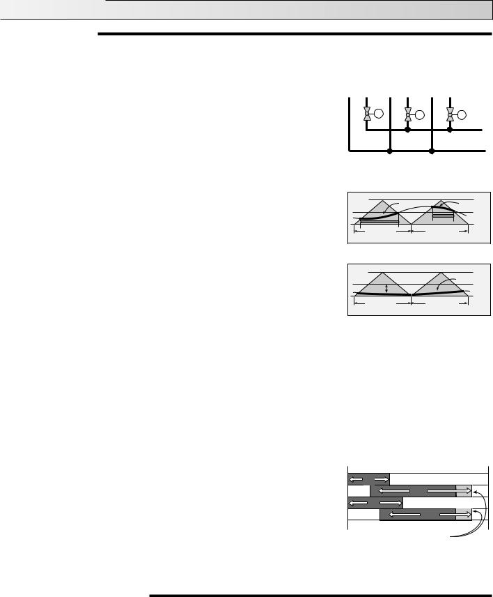
At the start of the night setback period the heat is turned off, but the heat contained within the slab or radiator continues to heat the building and there is a delay before the space temperature begins to drop. At the end of this delay the temperature within the building gradually decreases, and may eventually reach the required UnOccupied temperature after sufficient time has elapsed. Once the setback period is complete, the heat is turned on again but there is a long recovery time required to raise the space temperature to the desired setpoint. The length of the delay and recovery periods changes with outdoor temperature and is different for each zone within the building.
A comfortable setback can be provided if the control “learns” the response time for each zone within the building. Based on the zone’s response time, the control can then calculate an Optimum Stop time and an Optimum Start time. At the Optimum Stop time the control turns off the zone valve or pump in order to overcome the delay period and at the Optimum Start time, the control starts to raise the zone temperature in order to overcome the recovery period. This allows night setback to be used with most heating systems.
Optimum Start / Stop with Water Temperature Boost ¾¾
When Optimum Start / Stop is combined with Outdoor Reset, the control can boost the water temperature during the recovery period. This provides a faster recovery and allows a longer setback for greater energy savings.
The accuracy of the Optimum Start / Stop routine depends on the feedback available to the control.
10 P.M. |
11 P.M. |
8 A.M. |
11 A.M. |
|
Setback Period |
|
|
Occ |
|
|
|
70°F (21°C) |
|
|
|
|
|
|
UnOcc |
|
|
|
65°F |
|
|
|
(18°C) |
|
Delay |
Recovery |
|
|
Period |
Period |
|
9 P.M. |
10 P.M. |
5 A.M. |
8 A.M. |
|
|
Setback Period |
|
Occ |
|
|
Room Temperature |
70°F |
|
|
|
(21°C) |
|
|
UnOcc |
|
|
|
|
Optimum |
|
Optimum |
65°F (18°C) |
Stop |
|
Start |
|
|
Delay |
Recovery |
|
|
Period |
Period |
|
9 P.M. |
10 P.M. |
6 A.M. |
8 A.M. |
|
|
Setback Period |
|
Occ |
|
|
Room Temperature |
70°F |
|
|
|
(21°C) |
|
|
UnOcc |
Optimum |
|
Optimum |
65°F (18°C) |
Stop |
|
Start |
|
|
Delay |
Shorter |
|
|
Period |
Recovery |
|
|
|
Period |
|
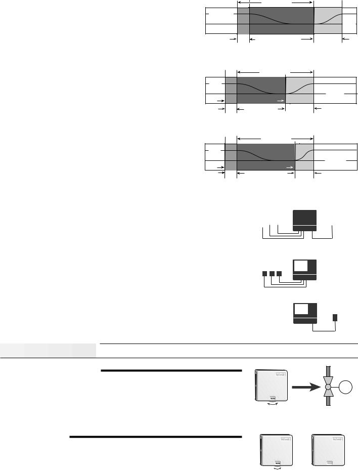
Optimum Start / Stop with both Outdoor and Indoor Sensors ¾¾¾¾¾¾
The response time of the building varies with outdoor temperature and is also different for each zone. The most accurate Optimum Start / Stop routine is therefore achieved when both the indoor and outdoor temperatures are monitored during transitions between UnOccupied and Occupied modes.
Optimum Start / Stop with only Indoor Sensors ¾¾¾¾¾¾¾¾¾¾¾¾¾
When only indoor temperature feedback is available, the control must base all Optimum Start / Stop calculations on indoor temperature only. If there are large variations in outdoor temperature, this method cannot provide the same level of accuracy as when both indoor and outdoor sensors are used.
Optimum Start / Stop with only an Outdoor Sensor ¾¾¾¾¾¾¾¾¾¾¾
Every building, and often each zone within the building, has a different response time. When only an outdoor sensor is used, the control must assume a particular response time for the entire building. Therefore this is generally the least accurate method of calculating Optimum Start / Stop times.
|
Room |
|
Outdoor |
|||||||
Temperature |
|
|||||||||
|
Sensor |
|||||||||
Units (RTU's) |
|
|||||||||
|
|
|
|
|
|
|
|
|
|
|
|
|
|
|
|
|
|
|
|
|
|
Room
Temperature
Units (RTU's)
Outdoor
Sensor
Sequence of Operation 


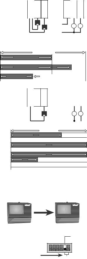
POWERING UP THE CONTROL
After the Zone Control 368 is powered up, a software version code is displayed for 2 seconds and the red indicator lights are then turned on for 4 seconds. Once the control is powered up, the green Power light remains on continuously. For the first fifteen minutes after power up, the Test light flashes and the control responds immediately to setting changes. This allows the installer to test the operation of the system. After fifteen minutes, the control enters its normal operating mode in which reactions to setting changes are significantly slower. A slower reaction time allows the control to provide a more stable room temperature.
ZONING OPERATION
The 368 can directly control the temperature of up to 4 One Stage heating zones or 2 Two Stage heating zones or a combination of One Stage and Two Stage zones. In order to measure the indoor temperature, each zone requires either an Indoor Sensor or a Room Temperature Unit (RTU). With an RTU the desired zone temperature is set using the RTU dial, but with an Indoor Sensor the desired zone temperature is fixed at 72°F (22°C).
M
70
Only in the first 15 minutes after power up, does the control respond immediately to settings adjustments.
70
RTU Indoor Sensor
3
Common Blocks ¾¾¾¾¾¾¾¾¾¾¾¾¾¾¾¾¾¾¾¾¾¾¾¾¾¾¾
The 368 has 2 common blocks for both the RTU inputs and the relay outputs. Each common block has a terminal starting with Com (Eg. Com Sen or Com 1-2 ). Each common block can be used for either two One Stage zones or one Two Stage zone.
One Stage Common Blocks ¾¾¾¾¾¾¾¾¾¾¾¾¾¾¾¾¾¾¾¾¾
If an RTU is connected to the lowest number in the common block, a One Stage common block is created.
Example An RTU connected between the terminals Com Sen — RTU 1 is used to control the output relay 1, and an RTU connected between the terminals Com Sen — RTU 2 is used to control the output relay 2.
Note If only one RTU is used, it must be placed on the lower number in the common block. In the above example this would be Com Sen — RTU 1 controlling output relay Com 1-2 — 1.
5 6 7
Com RTU RTU
Sen 1 2
H
H
15 16 17
Com
1-2 1 2
C |
M |
M |
|
||
R |
Zone 1 |
Zone 2 |
|
|
PID Zoning Logic
The 368 operation is based on a 15 minute cycle. During each cycle, the control turns on the zone relay for a specific on time. This zone on time is calculated based on the PID response of the zone during the previous 15 minute period. If the zone needs more heat, the on time is increased and if the zone needs less heat, the on time is reduced. In order to prevent short cycling, the 368 ensures that the zone relays remain on or off for at least 3 minutes.
15 minute Cycle |
|
Relay On Time |
|
Relay On Time |
|
|
More Heat |
Relay On Time |
Less Heat |
Two Stage Common Blocks ¾¾¾¾¾¾¾¾¾¾¾¾¾¾¾¾¾¾¾¾¾
When a single RTU is connected to the highest terminal number in the common block, a Two Stage common block is created. The single RTU therefore controls two output relays: a Lo stage relay and a Hi stage relay.
Example An RTU connected between the terminals Com Sen — RTU 2 is used to control the output relays 1 and 2. Relay 1 is the Lo stage output relay and relay 2 is the Hi stage output relay.
5 6 7
Com RTU RTU
Sen 1 2
H
C
R
|
15 |
16 |
17 |
|
||
|
Com |
|
|
|
|
|
|
1-2 |
1 |
2 |
|
||
|
|
|
M |
M |
||
|
|
|
||||
|
|
Lo |
|
Hi |
||
|
Stage |
|
Stage |
|||
PID Zoning logic
The temperature within each Two Stage zone is controlled by varying the on time of the output relays over a 15 minute period. During light loads, the 368 cycles the Lo stage relay on and off. As the load increases, the Lo stage relay on time increases until it reaches a maximum of 15 minutes. The Hi stage relay is then turned on and its on time is increased as the load increases. When the heating load decreases again, the on time of the Hi stage relay is reduced until the Hi stage relay is turned off completely. The control then starts to reduce the on time of the Lo stage relay.
|
|
15 minute Cycle |
Lo Stage |
On |
On |
Hi Stage |
Off |
|
Lo Stage |
|
On |
Hi Stage |
Off |
|
Lo Stage |
|
On |
Hi Stage |
|
On |
Lo Stage |
Off |
|
Zone Control Load Staggering and Synchronization ¾¾¾¾¾¾¾¾¾¾¾¾¾¾¾¾¾¾¾¾¾¾¾¾¾¾¾¾¾
The 368 staggers the operation of the zones in order to achieve a steady load on the boiler while minimizing boiler running time and preventing boiler short cycling. Multiple Zone Controls can be connected together to increase the number of zones. Each of the Zone Controls synchronizes its zone operating cycles based on the Zo In input from the other Zone Controls. This results in a more stable system flow rate and improved boiler operation.
Zone Control Operation with a tekmar House Control |
tekmar Zone Control |
tekmar Zone Control |
The 368 can communicate with a tekmar House Control in order to provide indoor temperature feedback, turn on the system pump and operate the boiler. When multiple Zone Controls are used, each Zone Control sequentially passes the information to the tekmar House Control. This ensures that the heat requirements of all zones are satisfied. When the 368 is requesting heat from the House Control, the Heat Required light is turned on.
Fast Acting Zone Valves or Zone Pumps ¾¾¾¾¾¾¾¾¾¾¾¾¾¾¾
If the Thermal Motor DIP switch is set to Off, the 368 assumes that fast acting (electric motor) zone valves or zone pumps are connected to the zone relays. The Heat Required light is therefore turned on as soon as the first zone relay is turned on. One minute before the last zone relay is turned off, the 368 purges the boiler by signaling to the House Control to turn off the boiler and keep the system pump operating.
Thermal Motor
Fast acting |
|
zone valve |
|
or zone pump |
Off |
4
Loading...