


- Data Brochure |
D 508 |
Thermostat 508 and 509 |
04/12 |
|
|
Replaces: 05/10
Table of Contents
Display / Keypad Operation............ |
pg 1 |
Display Symbols ............................. |
pg 2 |
General ........................................ |
pg 2-3 |
Sequence of Operation................ |
pg 3-4 |
Installation - Slab Sensor 079...... |
pg 4-6 |
Installation - Thermostats ............ |
pg 7-8 |
Wiring Examples........................ |
pg 9-10 |
User Interface ................................ |
pg 11 |
Menus ....................................... |
pg 12-14 |
View Menu.............................. |
pg 12 |
Adjust Menu .......................... |
pg 13 |
Schedule Menu ...................... |
pg 14 |
Error Messages ........................... |
pg 14 |
Technical Data .............................. |
pg 15 |
Warranty ....................................... |
pg 16 |
This brochure is for Thermostats 508 and 509 (with sensor). The section on the 079 slab sensor installation is for the 509 only!
Display / Keypad Operation
The thermostat’s display has four distinct fields. These fields are the Menu field, the Item field, the Number field and the Status field. The four buttons on the face of the thermostat are used to navigate through the menus and items to view and / or adjust the desired settings.
Displays the |
Displays an abbreviated |
current |
name of the selected item |
menu |
|
AWAY
Displays the current value
of the selected item
Displays the current status of the thermostat's inputs, outputs and operation
Selects Menus, Items
and adjusts settings
1 of 16 |
© 2012 |
D 508 - 04/12 |
Display Symbols
Warning
Displays when an error exists.
Access Level
Displays when in the user access level.
Heat One
Displays when the heat contact is on.
General
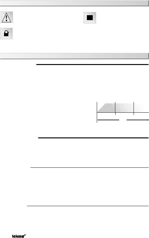
CYCLES PER HOUR
The thermostat operation is based on cycles per hour. The number of cycles per hour is adjustable through the HEAT CYC setting in the Adjust menu. During each cycle that heating is required, the thermostat turns on the Heat relay for a calculated amount of time. This amount of time is the “ON time”. The ON time is calculated based on the requirements of the zone. If the zone requires more heating, the ON time is increased. If the zone requires less heating, the ON time is reduced.
In order to prevent short cycling of the heating relay, the |
|
|
Cycles Per Hour |
||||
thermostat ensures that the relay remains on or off for |
|
|
|
|
|
|
|
|
|
|
|
|
|
|
|
a minimum amount of time. |
|
|
|
|
|
|
|
on |
off |
|
on |
off |
on |
off |
|
An AUTO CYC setting is available for the heating cycle.
Cycle Length
This setting allows the thermostat to determine the
Time
best number of cycles per hour that balances both temperature swings and equipment cycles.
AUXILIARY SENSOR
The thermostat has a single built-in sensor to measure air temperature at the thermostat. In addition to the built-in sensor, the thermostat has terminals to connect one auxiliary sensor. This sensor can be either an indoor sensor, a slab sensor, or an outdoor sensor.
Indoor Sensor
An indoor sensor is used to measure the air temperature in the zone that the thermostat is controlling. The temperature being read by the indoor sensor is used in the calculations of the ON time for the relay in the thermostat. This setting is made through the Adjust menu of the thermostat. If the built-in sensor is set to ON and the auxiliary sensor is set to Indoor, the temperatures of the sensors are averaged and used to calculate the ON time of the relay.
Slab Sensor
A slab sensor is used to measure the slab temperature in the zone that the thermostat is controlling. The temperature being read by the slab sensor is used in the calculations of the ON time for the Heat relay and allows the thermostat to operate the slab between the slab minimum and slab maximum settings.
© 2012 |
D 508 - 04/12 |
2 of 16 |

Outdoor Sensor
An outdoor sensor can be connected to the thermostat. The temperature measured by an outdoor sensor does not affect the ON time of the relay and is only used for display purposes.
ACCESS LEVELS
The 508 thermostat has two access levels. These access levels restrict the number of items available in the menus of the thermostat. The two access levels are User and Installer. This selection is made using the DIP switch located on the circuit board inside the thermostat.
Installer access level - allows the installer to adjust all of the settings in the thermostat including those required to match the thermostat to the mechanical system and the devices used.
User access level - allows the end user to adjust the temperatures used by the thermostat.
508
C |
3 |
|
V 24 |
Thermostat 508 |
|
944-02 |
|||||
R |
4 |
|
|
|
|||||||
|
|
|
|
|
|
|
One Stage Heat |
|
|
|
|
Rh |
5 |
|
|
|
|
|
|
|
|
|
|
|
|
|
|
|
|
|
Power: 24 V ±10% 50/60 Hz 1.5 VA. |
||||
6 W |
|
|
|
|
|||||||
|
|
|
Relay: 24 V (ac) 2 A Class 2 |
||||||||
|
|
|
|||||||||
|
|
|
|
|
|
|
|||||
For 3 wires, |
Made in |
|
|
|
|
||||||
install jumper |
|
|
|
|
|||||||
Canada |
|
|
|
|
|||||||
R to Rh |
|
|
|
|
|||||||
|
|
|
|
|
|||||||
|
|
|
|
|
|
|
Meets Class B: |
|
Apr 2010 |
||
|
|
|
|
|
|
|
Canadian ICES |
|
|||
|
|
|
|
|
|
|
FCC Part 15 |
|
Lot 1234 |
||
|
|
|
|
|
|
|
Access level |
||||
|
|
|
|
|
NO |
||||||
|
|
|
|
POWER |
Installer |
|
|
|
User |
||
|
|
|
|
1 |
|
2 |
Not used |
2 1 |
|
ON |
|
|
|
|
|
|
|
|
|
|
|||
|
|
|
|
Sensor |
|
|
|
|
|
||
|
|
|
|
|
|
|
|
|
|
|
|
Dip Switch
Set to User access level once installation and settings have been completed.
Note: DIP switch 2 is not used.
Sequence of Operation
AIR SENSOR(S) ONLY OPERATION
When operating with only an air sensor, the ON time for the Heat relay is calculated to satisfy the requirements of the air sensor.
SLAB SENSOR ONLY OPERATION
When operating with only a slab sensor, the ON time for the Heat relay is calculated to satisfy the requirements of the slab sensor. The thermostat operates to maintain the slab at the minimum slab temperature setting.
NOTE: Operating with only a slab sensor can lead to either overheating or underheating of the space.
AIR AND SLAB SENSOR OPERATION
When operating with both air and slab sensors, the thermostat calculates an ON time for the Heat relay to satisfy the slab sensor’s requirements and an ON time to satisfy the air sensor’s requirements. The Heat relay operates for the longer of these two ON times.
During light heating loads, overheating can occur due to the minimum slab temperature requirements.
During heavy heating loads, the maximum slab temperature setting limits the ON time of the Heat relay. In this situation, underheating can occur.
3 of 16 |
© 2012 |
D 508 - 04/12 |

MODE
Heat In the heat mode, the Heat relay is operated to satisfy the temperature requirement of the zone.
Off In the OFF mode, the Heat relay is not operated.
NOTE: If an air or slab sensor is active in the OFF mode, a freeze protection is enabled that allows the Heat relay to be operated to keep the zone above 35°F (2°C).
GETTING READY
Check the contents of this package. If any of the contents are missing or damaged, please contact your wholesaler or tekmar sales representative for assistance.
Type 508 Includes: • One Thermostat 508 • Data Brochure D 508 • User Brochure U 508
Type 509 Includes: • One Thermostat 508 • One 079 Slab Sensor • Data Brochure D 508 User Brochure U 508
SLAB SENSOR 079
The tekmar Slab Sensor 079 has a stainless steel sleeve which is designed for use in concrete, thin-set or grout. The 079 is supplied with 10’ (3 m) of 2 conductor zipcord.
Installation - Slab Sensor 079
STEP ONE |
|
INSTALLING THE SENSOR |
|
New Installations
Thin-Set or Thin-Pour Applications
Tiles
If the floor covering is to be installed over either
a thin-set or thin-pour material of sufficient Electric depth, the 079 slab sensor can be placed Cables
directly into either the thin-set material or the thin-pour material and covered over. Ensure that the sensor is located in such a position that the attached wire is able to reach to a suitable junction location. Splices within the thin-set or
thin-pour should be avoided to ensure trouble free operation. The sensor should be located mid way between the heating elements to ensure a proper temperature reading.
Thin Floor Coverings (less than 3/8” (10 mm)) |
|
If a thin floor covering is to be installed directly |
|
to the subfloor, a groove 1/8” (4 mm) wide by |
Hardwood |
1/16” (2 mm) deep can be cut into the surface of |
|
the subfloor to accommodate the wire for the |
Subfloor |
sensor. Ensure that the sensor is located in |
|
such a position that the attached wire is able |
|
to reach to a suitable junction location. Splices |
|
under the floor covering should be avoided to |
|
ensure trouble free operation. A groove 3/16” |
|
(5 mm) wide by 3/16” (5 mm) deep by 1-3/4” |
|
(45 mm) long should be cut to accommodate the sensor. The sensor should be located mid way between the heating elements to ensure a proper temperature reading.
© 2012 |
D 508 - 04/12 |
4 of 16 |

Thick Floor Coverings (greater than 3/8” (10 mm))
If a thick floor covering is to be installed directly to the subfloor, a groove 1/8” (4 mm) wide by 1/16” (2 mm) deep can be cut into the back of the flooring material to accommodate the wire for the sensor. Ensure that the sensor is located in such a position that the attached wire is able to reach to a suitable junction location.
Splices under the floor covering should be avoided to ensure trouble free operation. A groove 3/16” (5 mm) wide by 3/16” (5 mm) deep by 1-3/4” (45 mm) long should be cut to accommodate the sensor. The sensor should be located mid way between the heating elements to ensure a proper temperature reading.
Hardwood
Subfloor
NOTE: If it is not practical to cut a groove in the surface covering, follow the installation method used for thin floor coverings.
Retrofit Installations
Tile Floor Coverings
If a Slab Sensor 079 is to be installed into an existing tile floor with sufficiently large grout lines, the sensor and wire can be installed in one of the grout lines between the tiles. Select a low traffic area of the floor that is mid way between the heating elements for the sensor location. Ensure that the sensor is
located in such a position that the attached wire |
Tiles |
|
Thin-set |
||
is able to reach to a suitable junction location. |
||
|
||
Splices within the grout should be avoided to |
Subfloor |
|
ensure trouble free operation. Remove the |
|
|
appropriate grout line and place the sensor and |
|
|
wire in the floor. Re-grout the area. |
|
Installing the Sensor to the Bottom of a Subfloor
If the sensor is to be installed to the bottom of a subfloor, cut a piece of 1” (25 mm) thick rigid insulation into a 6” (150 mm) by 6” (150 mm) square. A groove 3/16” (5 mm) wide by 3/16” (5 mm) deep by 1-3/4”
(45 mm) long should be cut into the insulation |
Subfloor |
|
|
||
to accommodate the sensor. Place the sensor |
|
|
in the groove and sandwich the sensor between |
|
|
the insulation and the subfloor. Use a suitable |
|
|
fastening method to affix the insulation to the |
|
|
subfloor. |
|
|
STEP TWO |
WIRING AND TESTING THE SENSOR |
|
Caution: Do not run sensor wires parallel to telephone or power cables. If the sensor wires are located in an area with strong sources of electromagnetic interference, shielded cable or twisted pair should be used or the wires can be run in a grounded metal conduit.
The Slab Sensor 079 is supplied with 10’ (3 m) of cable. If a longer length is required, 24 AWG or larger wire can be spliced onto the two wires from the sensor. The splices should be properly soldered and protected in an accessible junction box. Follow the sensor testing instructions given in this brochure and then connect the wires to the control.
5 of 16 |
© 2012 |
D 508 - 04/12 |
 Loading...