


 Loading...
- Data Brochure |
D 371 |
House Control 371 |
07/96 |
Occupied |
Power |
WWSD |
UnOccupied |
|
|
|
|
DHW |
|
Maximum |
|
|
|
|
Demand |
|
Supply |
|
Optimum Start / Stop |
|
|
|
|
Setpoint |
|
Minimum |
|
|
|
|
Demand |
|
Boiler |
|
Timer Active |
|
24 hr. Timer |
|
70°F |
|
|
|
|
|
12 hrs. |
|
(21°C) |
DHW |
1 |
Zone 1 / |
• Dial the desired duration |
6 |
18 |
|
|
Pump |
Cooling |
|
of the UnOccupied period. |
|
|
System |
2 |
Zone 2 |
||
• Press start button at the time of day |
|
|
|
|
|||
you want the UnOcc. period to begin. |
|
|
|
|
Pump 1 |
|
|
Timer Active light turns on. |
|
|
|
|
System |
3 |
Zone 3 |
|
0 |
24 |
40 |
100 |
Pump 2 |
|
Zone 4 / |
|
UnOccupied |
(4) |
(38) |
Boiler |
4 |
||
|
|
Duration |
UnOccupied |
|
|
Open |
|
Start |
|
|
|
|
90 |
5 |
CloseZone 5 / |
0 = always Occupied |
|
|
70 |
|
of full |
||
24 = always UnOccupied |
|
|
|
|
|||
|
|
|
|
|
50 |
% output |
|
|
|
|
|
|
30 |
|
|
House Control 371 |
|
|
10 |
|
N R T L / C |
||
Five Zones, DHW, Boiler & Mixing |
|
|
|
|
LR 58223 |
||
The House Control 371 is a microprocessor-based control that provides individual temperature control for up to 5 zones. Each zone can be either connected to the boiler (hot water) loop or to the mixing (warm water) loop. The supply water temperature to the zones is modulated based on both the outdoor temperature and indoor temperature feedback from each of the zones. This outdoor reset strategy reduces indoor temperature swings and increases system efficiency. Other energy saving functions include a heating system Warm Weather Shut Down (WWSD) and the ability to lower indoor temperatures for a night setback period. The control has an Optimum Start / Stop function which automatically calculates when to bring each zone out of night setback in order to ensure they are returned to their normal operating temperatures as the setback period ends. The 371 allows integration of an indirect fired DHW tank into the system. This helps provide faster DHW tank pick-up times and greater energy savings. The control can also receive a setpoint demand on either the mixing loop or the boiler loop for snow melting, hot tubs, or other loads.
Control Strategy ................... |
pg. 2 |
Testing the Control ...... |
pg. 16 |
Sequence of Operation ........ |
pg. 6 |
Error Messages ............ |
pg. 19 |
Installation ............................ |
pg. 10 |
Technical Data .............. |
pg. 20 |
Settings ................................. |
pg. 14 |
Limited Warranty .......... |
pg. 20 |

 Occupied

 UnOccupied

 Optimum Start / Stop
|
Timer Active |
24 hr. Timer |
|
|
12 hrs. |
• Dial the desired duration of the |
6 |
18 |
UnOccupied period. |
||
• Press start button at the time of day |
|
|
you want the UnOcc. period to begin. |
|
|
Timer Active light turns on. |
|
|
|
0 |
24 |
UnOccupied
Duration
Start |
0 = always Occupied |
|
24 = always UnOccupied |
70°F
(21°C)
40 |
100 |
(4) |
(38) |
UnOccupied |
|
House Control 371
Five Zones, DHW, Boiler & Mixing
|
Power |
|
|
|
WWSD |
|
DHW |
|
|
|
Maximum |
|
Demand |
|
|
|
Supply |
|
|
|
|
||
|
Setpoint |
|
|
|
Minimum |
|
Demand |
|
|
|
Boiler |
|
DHW |
|
|
|
Zone 1 / |
|
Pump |
|
1 |
Cool |
|
|
|
|
|
||
|
System |
|
|
|
Zone 2 |
|
|
2 |
|||
|
Pump 1 |
|
|||
|
|
|
|
|
|
|
System |
|
|
|
Zone 3 |
|
|
3 |
|||
|
Pump 2 |
|
|||
|
|
|
|
OpenZone 4 / |
|
|
Boiler |
|
|||
|
|
4 |
|||
|
|
|
|
|
|
|
|
CloseZone 5 / |
|||
|
90 |
|
5 |
||
|
|
|
|
||
|
|
|
|
of full |
|
|
70 |
|
|
|
|
|
|
|
|
|
|
|
50 |
% output |
|||
|
30 |
|
|
|
|
|
|
|
|
|
|
|
|
|
|
|
R |
10
N R T L / C
LR 58223
|
Thermal Motor |
|
DHW during UnOcc. |
Occ/UnOcc |
Optimum Start |
|
Floating |
Permitted |
Mixing |
|
Zone 1 Cool |
Zone 1,2 3 4 5 1 |
2 3 4 5 Zo Setpnt |
|
Zone 1 Heat |
Occ. only |
Boiler |
Off |
Var. Speed |
|
2 |
|
170°F |
|
2 |
1 |
|
|
1 |
||
|
|
|
|
||
|
3 |
|
|
|
3 |
0.2 |
3.6 |
120 |
220 |
0.2 |
3.6 |
Heating Curve Max. Supply / Setpnt Boiler Heating
130°F |
Curve |
|
|
100 |
|
Test |
Off |
165 |
Min. Boiler
Supply
Made in Canada by
tekmar Control Systems Ltd.
Power |
120 V 50/60 Hz 1500 VA |
|
Var. Pump |
240 |
V 50/60 Hz 2.4 A 1/6 hp, fuse T2.5 A 250 V |
Relays |
120 |
V (ac) 3.2 A 1/4 hp, pilot duty 240 VA |
|
|
|
|
|
|
|
|
Do not apply power here |
|
|
Caution: Signal wiring must be rated at least 300V |
|
|||||||||||||
1 |
2 |
3 |
4 |
5 |
6 |
7 |
8 |
9 |
10 11 12 13 |
14 15 16 17 |
18 19 |
20 21 22 23 24 25 26 27 28 29 30 31 |
2 |
||||||||||||
Sys |
Sys |
Power |
Var. |
Com RTU RTU Com RTU RTU RTU Com UnO |
Zo |
Com Boil |
Sup |
Out |
|
DHW DHW Setp Com |
|
Com |
|
Opn |
Cls |
H1117 |
|||||||||
P 2 |
P 1 |
N |
L |
Pmp |
Sen |
1 |
2 |
Sen |
3 |
4 |
5 Sen |
Sw |
In |
Sen Sen Sen |
Sen |
Boiler |
Pmp Dem Dem |
1-2 1 |
2 |
3-5 |
3 |
4 |
5 |
|
|
Output |
|
|
|
|
|
|
|
|
|
|
|
|
|
|
|
|
|
|
|
|
|
|
|
|
|
Mixed System |
|
|
|
|
|
|
|
|
|
|
|
|
|
|
|
|
|
|
|
|
|
|
|
|
|
Pump |
|
|
|
|
|
|
|
|
|
|
|
|
|
|
|
|
|
|
|
|
|
|
OR |
|
|
Output |
|
|
|
|
|
|
|
|
|
|
|
|
|
|
|
|
|
|
|
|
|
|
|
|
|
Boiler System |
|
|
|
|
|
|
|
|
|
|
|
|
|
|
|
|
|
|
|
|
|
|
|
|
|
Pump |
|
|
|
|
|
|
|
|
|
|
|
|
|
|
|
|
|
|
OR |
|
|
|
|
|
|
Input |
|
|
|
|
|
|
|
|
|
|
|
|
|
|
|
|
|
|
|
|
|
|
|
|
|
|
|
|
|
|
|
|
|
|
|
|
|
|
|
|
|
|
|
|
|
|
|
|
|
|
|
120 V (ac) |
|
|
|
|
|
|
|
|
|
|
|
|
|
|
|
|
|
|
|
|
|
|
|
|
|
Power |
|
|
|
|
|
|
|
|
|
|
|
|
|
|
|
|
|
|
|
|
|
|
|
|
|
Supply |
|
|
|
|
|
|
|
|
|
|
|
|
|
|
|
|
|
|
|
|
|
|
|
|
|
Output |
|
|
|
|
|
|
|
|
|
|
|
|
|
|
|
|
|
|
|
|
|
|
|
|
|
Var. Speed |
|
|
|
|
|
|
|
|
|
|
|
|
|
|
|
|
|
|
|
|
|
|
|
|
|
Driven Pump |
|
|
|
|
|
|
|
|
|
|
|
|
|
|
|
|
|
|
|
|
|
|
|
|
|
Input |
|
|
|
|
Input |
|
|
|
Input |
|
|
Inputs |
|
|
Input |
Output |
|
Output |
|
||||||
tekmar RTUs or |
|
|
|
tekmar |
|
|
tekmar Zone |
|
|
Universal |
|
Outdoor |
Boiler |
|
|
DHW |
|
||||||||
Indoor Sensors |
|
|
|
Timer |
|
|
|
Control |
Sensors Included |
Sensor Included |
|
|
|
Pump |
|
||||||||||
M
Output
Mixing Valve &
Actuating Motor
 M
M
Output
Zone Valves or Zone Pumps
Output |
Cooling |
Input
Setpoint
Demand signal
Input
DHW
Demand signal
1

Control Strategy
OUTDOOR RESET
In order to properly control a hot water heating system, the heat supplied to the building must equal the heat lost by the building.
•The heat supplied to a building is proportional to the temperature of the water and the surface area of the heating element. A small surface area such as baseboard radiators requires a higher water temperature than a larger surface area such as radiant floors.
•The heat lost from a building is dependent on the outdoor temperature. As the outdoor temperature drops, the building heat loss increases.
Heating Curve ¾¾¾¾¾¾¾¾¾¾¾¾¾¾¾¾¾¾¾¾
A hot water heating system can be accurately controlled by modulating the supply water temperature as the outdoor temperature changes. Using this approach, the heat lost from the building is exactly matched by the heat input to the building. A tekmar reset control utilizes a heating curve to set the relationship between outdoor temperature and supply water temperature. The heating curve determines the amount the supply water temperature is raised for every 1° drop in outdoor air temperature. The heating curve is sometimes called an outdoor reset ratio.
Heating Curve Shift ¾¾¾¾¾¾¾¾¾¾¾¾¾¾¾¾¾¾
All heating curves begin at the heating curve starting point. If the heating curve starting point is adjusted, the heating curve will be parallel shifted. The heating curve starting point is either set manually through a dial, or it is determined automatically by the control through indoor temperature feedback.
Indoor Temperature Feedback ¾¾¾¾¾¾¾¾¾¾¾¾¾
Most buildings have internal heat gains due to people, passive solar heating and mechanical or electrical equipment. If only the outdoor temperature is measured, the control cannot compensate for these internal heat gains and the building may overheat. In order to prevent overheating, indoor temperature feedback should be combined with the outdoor reset strategy. From this indoor temperature feedback, the control can change the heating curve starting point in order to match the supply water temperature to the heat loss of the building. If the indoor temperature is too warm, the control automatically shifts the starting point and the heating curve down. If the indoor temperature is too cold, the control shifts the starting point and the heating curve up.
Warm Weather Shut Down (WWSD) ¾¾¾¾¾¾¾¾¾¾
When the outdoor air temperature is equal to the heating curve starting point, no additional heat is required in the building and therefore the heating system can be shut down. The WWSD point is normally the same as the heating curve starting point.
BOILER OPERATION
The supply water temperature from a boiler can be controlled by cycling the boiler on and off. Modulation of the boiler’s operating temperature in hot water heating systems not only provides more comfort but also offers significant energy savings. The cooler the boiler runs, the more efficient it is due to less heat losses up the flue and reduced boiler jacket losses.
Boiler Minimum Supply ¾¾¾¾¾¾¾¾¾¾¾¾¾¾¾¾¾
Most boilers require a minimum supply water temperature in order to prevent corrosion from flue gas condensation. The control should therefore only modulate the boiler supply water temperature down to the boiler manufacturer’s minimum recommended operating temperature. Some boilers are designed to condense and should be operated at low water temperatures as much as possible for maximum efficiency.
2
|
|
|
|
|
|
|
|
|
|
|
|
|
|
|
|
|
|
|
|
|
|
|
|
|
|
|
|
|
|
|
|
|
|
|
|
|
|
|
|
|
|
|
|
|
|
|
|
|
|
|
|
|
|
|
|
|
|
|
|
|
|
|
|
|
|
|
|
|
|
|
|
|
|
|
|
|
|
|
|
|
|
|
|
|
|
|
|
|
|
|
|
|
|
|
|
|
|
|
|
|
|
|
|
|
|
|
|
|
|
|
|
|
|
|
|
|
|
|
|
|
|
|
|
|
|
|
|
|
|
|
|
|
|
|
|
|
|
|
|
|
|
|
|
|
|
|
|
|
|
|
|
|
|
|
|
|
|
|
|
|
|
|
|
|
|
|
|
|
Outdoor |
|
|
Constant |
|
Heat |
|||||||||||||||||||||
Temperature |
Room Temperature |
|
Loss |
||||||||||||||||||||||||
|
Drop |
|
Increase |
||||||||||||||||||||||||
|
|
|
|
|
|
|
|
|
|
|
|
|
|
|
|
|
|
|
|||||||||
|
|
|
|
|
|
|
|
|
|
|
|
|
|
|
|
|
|
|
|
|
|
|
|
|
|
|
|
|
|
|
|
|
|
|
|
|
|
|
|
|
|
|
|
|
|
|
|
|
|
|
|
|
|
|
|
|
|
|
|
|
|
|
|
|
|
|
|
|
|
|
|
|
|
|
|
|
|
|
|
|
|
|
|
|
|
|
|
|
|
|
|
|
|
|
|
|
|
|
|
|
|
|
|
|
|
|
|
|
|
|
|
|
|
|
|
|
|
|
|
|
|
|
|
|
|
|
|
|
|
|
|
|
|
|
|
|
|
|
|
|
|
|
|
|
|
|
|
|
|
|
|
|
|
|
|
|
|
|
|
|
|
|
|
|
|
|
|
|
|
|
|
|
|
|
|
|
|
|
|
|
|
|
|
|
|
|
|
|
|
|
|
|
|
|
|
|
|
|
|
|
|
|
|
|
|
|
|
|
|
|
|
|
|
|
|
|
|
|
|
|
|
|
|
|
|
|
|
|
|
|
|
|
|
|
|
|
|
|
|
|
|
|
|
|
|
|
|
|
|
|
|
|
|
|
|
|
210 |
3.6 |
3.0 |
2.4 |
2.0 |
1.6 |
(99) |
|
190
(88)
|
|
|
|
|
|
|
170 |
temperature |
||
|
|
|
|
|
|
|
||||
|
|
|
1.2 |
|
(77) |
|
||||
|
|
|
|
|
|
|
150 |
|
||
|
|
|
1.0 |
|
(65) |
|
||||
|
Heating |
|
|
|
(54) |
water |
||||
|
|
|
0.8 |
|
|
130 |
|
|||
|
|
|
|
|
|
|||||
|
|
|
|
|
|
|
|
|
|
|
|
Curve |
|
0.6 |
|
|
|
|
|
|
Supply |
|
Starting |
|
|
|
110 |
|||||
|
Point |
|
0.4 |
|
(43) |
|
||||
|
|
|
|
|
|
|
|
|
90 |
|
|
|
|
0.2 |
|
(32) |
|
||||
|
|
|
|
|
|
|||||
|
|
|
|
|
|
70 |
|
|||
|
|
|
|
|
(21) |
|
||||
|
|
|
|
|
|
|
|
|
|
|
90 |
70 |
50 |
30 |
10 |
-10 |
°F |
(32) |
(21) |
(10) |
(-1) |
(-12) |
(-23) |
(°C) |
Outdoor air temperature
|
|
|
|
|
|
210 |
|
|
3.6 |
3.0 2.4 |
2.0 |
1.6 |
(99) |
|
|
|
|
|
|||||
|
|
|
|
|
|
190 |
|
|
Shift |
|
|
|
|
(88) |
temperature |
|
|
|
|
|
(65) |
||
Parallel |
|
|
|
|
1.2 |
170 |
|
|
|
|
|
150 |
|
||
|
|
|
|
|
(77) |
|
|
|
|
|
|
|
1.0 |
|
|
|
UP |
of |
Heating |
|
0.8 |
130 |
water |
|
|
|
|||||
|
|
DOWN |
Curve |
0.6 |
(54) |
|
|
|
|
110 |
Supply |
||||
|
|
|
|
|
|||
|
|
|
|
|
0.4 |
(43) |
|
|
|
|
|
|
0.2 |
90 |
|
|
|
|
|
|
(32) |
|
|
|
|
|
|
|
|
|
|
70
(21)
90 |
70 |
50 |
30 |
10 |
-10 |
°F |
(32) |
(21) |
(10) |
(-1) |
(-12) |
(-23) |
(°C) |
Outdoor air temperature
|
|
|
|
210 |
3.6 |
3.0 2.4 |
2.0 |
1.6 |
(99) |
|
190
(88)
|
|
|
|
|
|
|
|
|
|
|
170 |
temperature |
|
|
|
|
Boiler Minimum |
|
|
|
|
|
|
||||
|
|
|
|
1.2 |
|
(77) |
|
||||||
|
|
|
Supply Setting |
|
|
|
|
|
|
150 |
|
||
|
|
|
|
130°F |
|
|
|
|
|
|
|
||
|
|
|
|
|
|
|
1.0 |
|
(65) |
|
|||
|
|
|
|
|
|
|
|
|
water |
||||
|
|
|
|
|
|
|
0.8 |
|
|
130 |
|||
|
|
|
|
|
|
|
|
|
|
||||
|
|
|
|
|
|
|
|
|
(54) |
|
|||
|
|
|
|
|
|
|
0.6 |
|
|
|
|
|
Supply |
|
|
Point |
|
|
|
0.4 |
|
110 |
|||||
|
WWSD |
|
|
|
|
|
(43) |
|
|||||
|
|
70°F |
|
|
|
|
|
|
|
|
90 |
|
|
|
|
|
|
|
|
|
0.2 |
|
(32) |
|
|||
|
|
|
|
|
|
|
|
|
|
70 |
|
||
|
|
|
|
|
|
|
|
|
(21) |
|
|||
90 |
70 |
50 |
30 |
10 |
-10 |
°F |
(32) |
(21) |
(10) |
(-1) |
(-12) |
(-23) |
(°C) |
Outdoor air temperature
Boiler Differential ¾¾¾¾¾¾¾¾¾¾¾¾¾¾¾¾¾¾¾
An on / off boiler must be operated with a differential in order to prevent short cycling. When the supply water temperature drops below the bottom rail of the differential, the boiler is turned on. The boiler is then kept on until the supply water temperature rises above the top rail of the differential. If the differential is too wide, there can be large supply water temperature swings; however, if the differential is too narrow, the boiler short cycles and operates inefficiently. Some controls automatically calculate the boiler differential in order to achieve an appropriate balance between temperature swings and boiler efficiency. This also permits the control to adapt to changing loads and conditions.
Supply Water Temperature
165°F(74°C)
160°F (71°C)
155°F (68°C)
|
n |
|
o |
|
r |
o |
ile |
B |
|
B
o
ile
r
o
f f
Time
Differential = 10°F (5°C)
|
|
|
|
|
|
B |
|
|
|
|
|
|
o |
|
|
|
|
|
|
i |
|
|
|
|
|
|
l |
|
|
|
|
|
|
e |
|
|
|
|
|
n |
r |
|
|
|
|
o |
f |
|
|
|
|
|
|
|
o |
|
|
|
r |
|
|
f |
B |
o |
ile |
|
|
|
|
|
|
|
|
|||
|
|
|
|
|
||
|
|
|
|
|
|
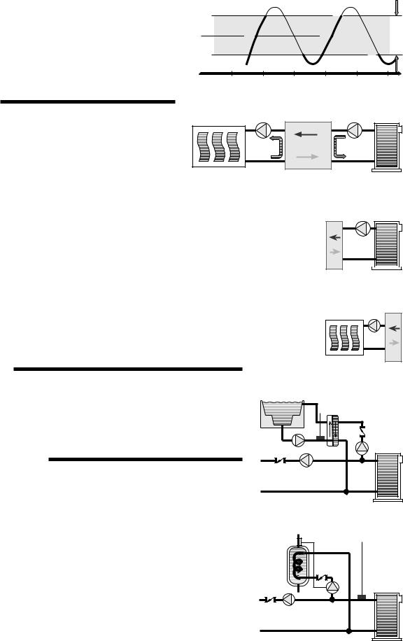
MIXING OPERATION
The full range of water temperatures required through a heating season can be provided with a standard (non-condensing) boiler by incorporating a modulating mixing device into the system. Mixing valves or variable speed injection pumps are commonly used to modulate both the system supply water temperature and the boiler return water temperature. The modulation of water temperatures improves comfort in the building and also protects the boiler from cool return water. For more detailed information on mixing methods consult Essay E 021.
System |
Mixing |
Boiler |
Loop |
Device |
Loop |
Boiler Protection ¾¾¾¾¾¾¾¾¾¾¾¾¾¾¾¾¾¾¾¾¾¾¾¾¾¾¾¾¾¾¾¾¾¾
Cool water is often returned to the boiler from low temperature radiant floor heating systems or when the |
|
|
heating system is recovering from night setback. This cool boiler return water may cause the boiler to operate |
|
|
at such a low temperature that the flue gases condense. Alternatively, when the boiler surfaces are hot due |
Mix |
|
to previous loads such as domestic hot water generation, the large temperature difference ( T) between the |
||
|
||
boiler and its return water can cause the boiler to become thermally shocked. Proper protection of the boiler |
|
|
under these circumstances requires a modulating mixing device that can temporarily reduce the heating |
|
|
load. This is normally accomplished by closing a valve or reducing the speed of an injection pump. |
|
System Maximum Supply ¾¾¾¾¾¾¾¾¾¾¾¾¾¾¾¾¾¾¾¾¾¾¾¾¾¾¾¾¾¾
Some systems, such as hydronic radiant floor heating, usually operate at water temperatures that are below the minimum boiler supply temperature. This is due to the large surface area of the floors which radiate a significant amount of heat at low water temperatures. Floor heating systems and flat panel convectors also have a maximum surface temperature limit for occupant health reasons. In such systems a modulating mixing device is normally required to limit the supply water temperature.
SETPOINT OPERATION
Mix
Some loads such as spa heating or pool heating require a fixed setpoint water supply temperature. The required setpoint water temperature can be either high temperature or low temperature. When a setpoint demand for high temperature water is present, the control should cycle a boiler on and off to maintain this temperature. For lower water temperature requirements, the control should operate a mixing device. If outdoor reset is used and a setpoint operation is required, the control should override the reset operation and increase the water temperature.
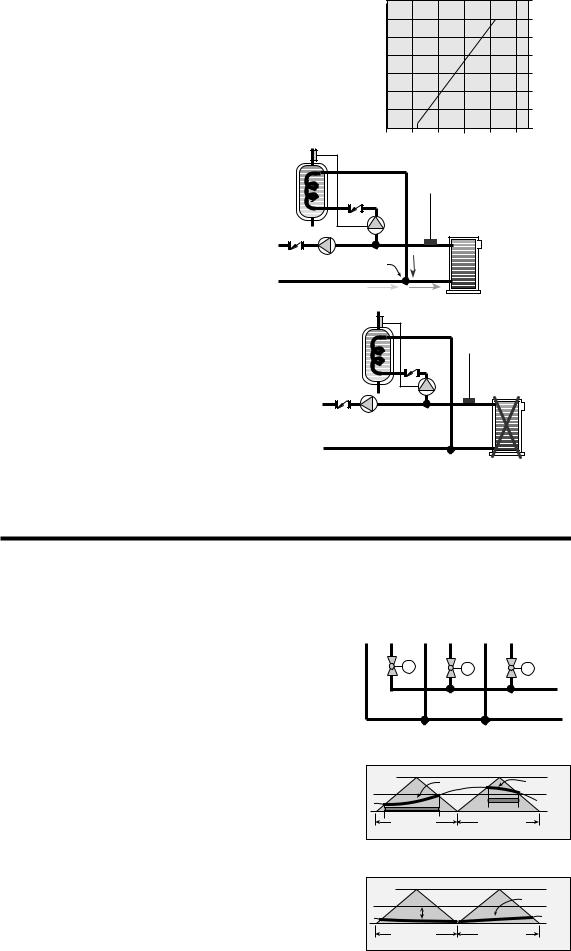
DOMESTIC HOT WATER (DHW)
An indirect fired DHW tank can be integrated into the hydronic heating system for greater system efficiency and faster DHW recovery.
DHW Supply ¾¾¾¾¾¾¾¾¾¾¾¾¾¾¾¾¾¾¾¾¾¾¾¾¾¾¾¾¾
Indirect DHW tanks are typically heated with a boiler water temperature of 180 to 200°F (82 to 93°C). When outdoor reset is used, the boiler supply water may be well below this temperature and therefore an outdoor reset override is required. When the DHW tank calls for heat, the control must turn on the appropriate pump and ensure there is hot boiler supply water.
DHW Priority ¾¾¾¾¾¾¾¾¾¾¾¾¾¾¾¾¾¾¾¾¾¾¾¾¾¾¾¾¾
It is often desirable to temporarily suspend the flow of heat to the heating system when the DHW tank calls for heat. This allows the DHW tank to recover faster than when both the DHW and heating system operate simultaneously. If the heating system has a large thermal mass, a relatively short interruption of the heat supply is not noticed by the occupants. Heating systems with a smaller thermal mass may cool down while the heating system is turned off.
P
3
DHW Priority Override |
|
|
|
|
7 |
|
|
|
|
|
|
|
|
(hours) |
|
||
There is always the possibility of an excessively long DHW call for heat due to a broken |
|
|
|
6 |
|
|||
freeze when there is a long DHW draw with DHW Priority selected. In order to prevent |
|
|
|
|
limittime |
minutes) |
||
pipe, faulty aquastat or other problems. At cold outdoor conditions the building may |
|
|
|
5 |
|
|
||
this, the control must override the DHW Priority and simultaneously operate the DHW |
|
|
|
4 |
demandpriority |
(minimum20 |
||
|
|
|
3 |
|||||
|
|
|
|
|
||||
and heating systems. The maximum time allotted for DHW Priority should decrease as |
|
|
|
|
|
|||
|
|
|
|
|
|
|||
the outdoor temperature drops. |
|
|
|
|
2 |
|
|
|
Boiler Shock Protection |
|
|
|
|
1 |
DHW |
|
|
|
|
|
|
|
|
|||
|
|
|
|
|
|
|
||
When DHW priority is used, the temperature within the heating |
-40°F |
-20 |
20 |
60 |
100°F |
|
|
|
(-40)°C |
(-29) |
(-7) |
(-16) |
(38)°C |
|
|
||
system terminal unit may be significantly lower than the boiler |
Outdoor air temperature |
|
|
|
||||
temperature once the DHW operation is complete. If the DHW pump |
|
|
|
|
|
|
|
|
or valve is simply turned off and the heating system pump turned on, |
|
|
|
|
|
|
|
|
a large |
T can develop across the boiler. This may induce thermal |
P |
|
|
|
|
|
|
shock of the boiler. In order to provide a smooth transition between |
|
|
|
|
|
|
|
|
the DHW and heating system loads, the control must simultaneously |
|
|
|
|
|
|
|
|
operate the DHW pump and heating system pump for a short period |
|
|
|
|
|
|
|
|
of time. This mixes the water returning to the boiler and minimizes |
Mixing |
|
|
|
|
|
|
|
the possibility of thermal shock. |
|
|
|
|
|
|
||
|
|
|
|
|
|
|
||
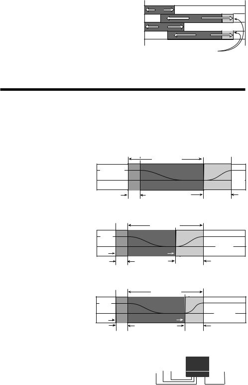
DHW Post Purge ¾¾¾¾¾¾¾¾¾¾¾¾¾¾¾¾¾¾¾
During the DHW operation, the boiler temperature is normally raised above 180°F (82°C). Once the DHW tank is satisfied, the residual heat within the boiler should be purged in order to reduce stand-by losses. When the heating system does not require heat, the boiler can be purged into the DHW tank. This is accomplished by turning the boiler off but keeping the DHW pump or valve operating for a purging period. If the boiler supply temperature drops below the DHW tank temperature, heat will be removed from the DHW tank. Therefore, the post purge is terminated if the boiler supply is not hot enough. This means that the DHW post purge will not always take the same length of time.
P
DHW Setback ¾¾¾¾¾¾¾¾¾¾¾¾¾¾¾¾¾¾¾¾¾¾¾¾¾¾¾¾¾¾¾¾¾¾¾¾¾¾¾¾¾¾¾¾¾¾
During the night, or when people are not within the building, energy can be saved by lowering the DHW tank temperature. A lower tank temperature is achieved when the system control ignores the call for heat from the DHW aquastat. In order to prevent a cold DHW temperature at the start of the Occupied period, the system control must raise the tank temperature before the setback period ends.
ZONING OPERATION
In a multiple zone heating system, the zones may have different internal heat gains, heat losses or different temperature settings. Each zone must therefore have individual temperature control. For maximum comfort, the heat should be continuously supplied to the zone at the same rate the zone is losing heat. The most accurate method of accomplishing this is by outdoor reset; however, it is not normally economical to modulate the supply water temperature to every zone.
Outdoor reset can be combined with zoning for a more cost effective solution. Through indoor sensors, a zone control can provide indoor temperature feedback to the outdoor reset control. The outdoor reset control will then adjust the supply water temperature to satisfy the zone with the highest water temperature requirement. Heat to the remaining zones will be cycled on and off by the zone control using zone valves or pumps. Since the heat is cycled on and off, accurate PID control logic should be provided to maintain a stable indoor temperature.
PID Zone Temperature Control ¾¾¾¾¾¾¾¾¾¾¾¾¾¾¾¾¾¾¾¾¾
90% |
85% |
100% |
on time |
on time |
on time |
M |
M |
M |
Heat
Source
Proportional (P)
In order to prevent indoor temperature swings, the heat supplied to each zone must be proportional to the heat required by the zone. Proportional control logic can be accomplished by pulse width modulation (PWM). A typical PWM system has a fixed operating cycle. During this operating cycle, the on time of the zone relay is varied based on the difference between the desired zone temperature and the actual zone temperature. As the zone temperature drops, the relay on time increases and as the zone temperature rises, the relay on time decreases.
72 °F |
10 minutes |
5 minutes |
(22°C) |
||
on |
|
70 °F |
|
(22°C) |
|
|
|
|
|
|
68 °F |
15 minutes |
15 minutes |
(20°C) |
Integral (I)
Controls that are strictly proportional suffer from a problem of offset. The amount of heat supplied to the zone depends on how far the space temperature is below the desired setpoint. This implies that as the heating load increases, the average room temperature droops. On the coldest day of the year, the most heat is required and therefore the room temperature must be coldest.
72 °F |
|
|
(22°C) |
|
13 minutes |
droop |
|
70 °F |
|
(21°C) |
|
|
|
68 °F |
15 minutes |
15 minutes |
(20°C) |
4
In order to overcome this offset, integral control logic is used. Only digital controls can provide integral control logic due to the lengthy response time of buildings. Integral control logic is based on time. The longer the room temperature is below the desired setpoint, the more heat is supplied to the room. With integral control logic, full heat can be supplied to the room on the coldest day of the year without requiring that the room be cold.
Derivative (D)
In order to speed up the control’s response to quick changes in the heating load, derivative control logic is required. However, sudden room temperature changes, for example from an open door or window, should be ignored by an intelligent control.
P + I + D = PID
If proportional, integral and derivative (PID) control logic are combined, the control is more able to prevent excessive temperature swings and provide a stable room temperature under all conditions. It not only takes into account how much the room temperature has drooped, but also how long there has been a droop and how fast the temperature is changing.
Zone Load Coordination ¾¾¾¾¾¾¾¾¾¾¾¾¾¾¾¾¾¾¾¾¾¾¾
In a multiple zone system, there can be sudden load changes on the boiler and system due to multiple zones turning on or off. These sudden load changes often lead to boiler short cycling and unnecessary mechanical stresses. The operation of the system can be improved by staggering the starting points of each zone relay within the operating cycle. Staggering of the zones maintains a relatively constant system flow rate which improves boiler operation. Controlled staggering can also minimize boiler running time and improve system efficiency when only a few zones are needed for short periods.
On |
Zone 1 |
Zone 2 |
On |
On |
Zone 3 |
Zone 4 |
On |
Post Purge (Boiler off, Pump on)
Zone Post Purge ¾¾¾¾¾¾¾¾¾¾¾¾¾¾¾¾¾¾¾¾¾¾¾¾¾¾¾¾¾¾¾¾¾¾¾¾¾¾¾¾¾¾¾¾
Before the last zone is turned off in a heating cycle, the boiler is turned off but the zone continues to draw heat from the boiler. This post purge of the boiler reduces stand-by losses and reduces overall energy consumption.
UNOCCUPIED (NIGHT SETBACK)
During the night, or at times when people are not within the building, energy can be saved by lowering the building temperature for an UnOccupied (Night Setback) period.
Due to the large thermal mass of buildings, it takes a long time for the indoor space temperature to significantly change whenever the heating system is turned on or off. The building heat up or cool down time is further increased when high mass heating systems are used (e.g. radiant floors). In most cases night setback cannot be used with these systems due to the long recovery time required in the morning. A typical system is demonstrated in the adjacent diagram.
At the start of the night setback period the heat is turned off, but the heat contained within the slab or radiator continues to heat the building and there is a delay before the space temperature begins to drop. At the end of this delay the temperature within the building gradually decreases, and may eventually reach the required UnOccupied temperature after sufficient time has elapsed. Once the setback period is complete, the heat is turned on again but there is a long recovery time required to raise the space temperature to the desired setpoint. The length of the delay and recovery periods changes with outdoor temperature and is different for each zone within the building.
A comfortable setback can be provided if the control “learns” the response time for each zone within the building. Based on the zone’s response time, the control can then calculate an Optimum Stop time and an Optimum Start time. At the Optimum Stop time the control turns off the zone valve or pump before the selected UnOcc time in order to overcome the delay period. At the Optimum Start time, the control starts to raise the zone temperature before the selected Occ time in order to overcome the recovery period. This allows night setback to be used with most heating systems.
Optimum Start / Stop with Water Temperature Boost ¾¾
When Optimum Start / Stop is combined with Outdoor Reset, the control can boost the water temperature during the recovery period. This provides a faster recovery and allows a longer setback for greater energy savings.
The accuracy of the Optimum Start / Stop routine depends on the feedback available to the control.
10 P.M. |
11 P.M. |
8 A.M. |
11 A.M. |
|
Setback Period |
|
|
Occ |
|
|
|
70°F (21°C) |
|
|
|
|
|
|
UnOcc |
|
|
|
65°F |
|
|
|
(18°C) |
|
Delay |
Recovery |
|
|
Period |
Period |
|
9 P.M. |
10 P.M. |
5 A.M. |
8 A.M. |
|
|
Setback Period |
|
Occ |
|
|
Room Temperature |
70°F |
|
|
|
(21°C) |
|
|
UnOcc |
|
|
|
|
Optimum |
|
Optimum |
65°F (18°C) |
Stop |
|
Start |
|
|
Delay |
Recovery |
|
|
Period |
Period |
|
9 P.M. |
10 P.M. |
6 A.M. |
8 A.M. |
|
|
Setback Period |
|
Occ |
|
|
Room Temperature |
70°F |
|
|
|
(21°C) |
|
|
UnOcc |
Optimum |
|
Optimum |
65°F (18°C) |
Stop |
|
Start |
|
|
Delay |
Shorter |
|
|
Period |
Recovery |
|
|
|
Period |
|
Optimum Start / Stop with both Outdoor and Indoor Sensors ¾¾¾¾¾¾
The response time of the building varies with outdoor temperature and is also different for each zone. The most accurate Optimum Start / Stop routine is therefore achieved when both the indoor and outdoor temperatures are monitored during transitions between UnOccupied and Occupied modes.
|
Room |
|
Outdoor |
|||||||
Temperature |
|
|||||||||
|
Sensor |
|||||||||
Units (RTU's) |
|
|||||||||
|
|
|
|
|
|
|
|
|
|
|
|
|
|
|
|
|
|
|
|
|
|
5
Optimum Start / Stop with only Indoor Sensors ¾¾¾¾¾¾¾¾¾¾¾¾¾¾¾¾¾¾¾
When only indoor temperature feedback is available, the control must base all Optimum Start / Stop calculations on only indoor temperature. If there are large variations in outdoor temperature, this method cannot provide the same level of accuracy as when both indoor and outdoor sensors are used.
Optimum Start / Stop with only an Outdoor Sensor ¾¾¾¾¾¾¾¾¾¾¾¾¾¾¾¾¾¾
Every building, and often each zone within the building, has a different response time. When only an outdoor sensor is used, the control must assume a particular response time for the entire building. Therefore this is generally the least accurate method of calculating Optimum Start / Stop times.
Room
Temperature
Units (RTU's)
Outdoor
Sensor
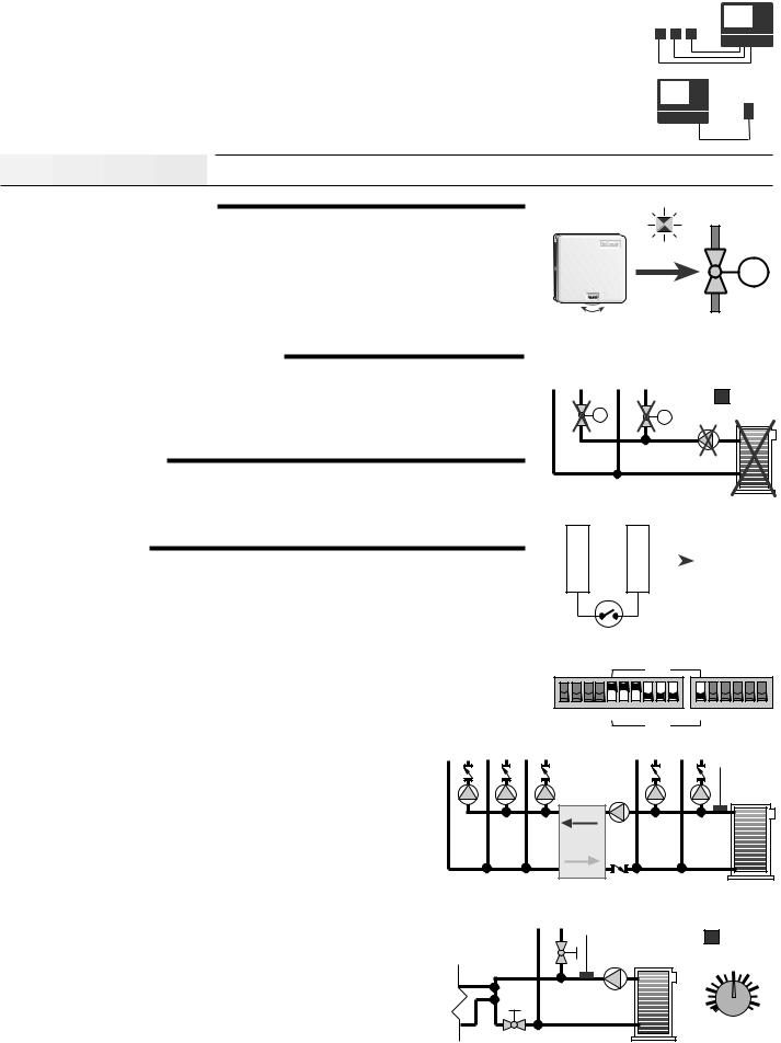
Sequence of Operation 


POWERING UP THE CONTROL
After the House Control 371 is powered up, a software version code is displayed for 2 seconds and then the red indicator lights are turned on for 4 seconds. When the control is powered up, the green Power light remains on continuously. For the first fifteen minutes after power up, the Test light flashes and the control responds immediately to changes of settings. This allows the installer to test the operation of the system. After 15 minutes the control enters its normal operating mode in which reactions to setting changes are significantly slower. A slower reaction time to setting changes allows the control to provide a stable room temperature.
WARM WEATHER SHUT DOWN (WWSD)
Test
M
70
Only in the first 15 minutes after power up, does the control respond immediatley to settings adjustments.
When the outdoor temperature rises above the highest Room Temperature Unit (RTU) dial setting and all heating zones are satisfied, the WWSD light is turned on and zone relays are turned off. When an external Zone Control input is used, the WWSD light is only turned on when all the zones connected to the 371 and all the zones connected to the Zone Control are satisfied.
SETPOINT OPERATION
The 371 can be used to supply a fixed water temperature whenever a setpoint demand is provided. If 120 V (ac) is applied to terminal Setp Dem (24), the control registers a setpoint demand and turns on the Setpoint Demand light. The setpoint load can be connected to either the boiler (hot water) loop or mixing (warm water) loop.
BOILER OPERATION
The 371 operates the boiler whenever there is a call for heat from boiler zones, mixing zones, DHW, or a setpoint load. The boiler supply water temperature is controlled by turning the boiler on and off. The 371 ensures sufficient heat is supplied to satisfy the demand for the hottest water temperature. In order to prevent boiler short cycling, the Boiler relay has a minimum off time of 20 seconds, and the boiler differential is automatically calculated.
Boiler Zones (hot water) ¾¾¾¾¾¾¾¾¾¾¾¾¾¾¾¾
A boiler zone is selected by setting the zone DIP switch to Boiler. Once heat is required, the 371 uses an outdoor reset strategy with indoor temperature feedback from each of the boiler zones.
Mixing Zones (warm water) ¾¾¾¾¾¾¾¾¾¾¾¾¾¾
|
WWSD |
M |
M |
4 24
Setp |
|
|
|
Setpoint |
|
|
|
Demand |
|
|
|
|
L Dem
Mixing
1 2 3 4 5 Zo Setpnt
Boiler
A mixing zone is selected by setting the zone DIP switch to Mixing. When a mixing zone requires heat, the speed of the variable speed injection pump increases or the mixing valve opens. The 371 may also raise the boiler water temperature to satisfy the mixing heating load.
Setpoint Boiler Supply ¾¾¾¾¾¾¾¾¾¾¾¾¾¾¾¾¾
If the Setpnt DIP switch is set to Boiler and setpoint operation is required, the 371 targets a boiler temperature of at least 180°F (82°C).
Boiler Maximum Supply ¾¾¾¾¾¾¾¾¾¾¾¾¾¾¾¾¾
mixing zones
At no time does the 371 allow the target boiler supply water temperature to exceed 212°F (100°C).
Mixing |
Device |
Boiler Minimum Supply ¾¾¾¾¾¾¾¾¾¾¾¾¾¾¾¾
The 371 has a Min. Boiler Supply dial which sets a minimum target boiler supply temperature. This dial has an Off position for condensing and electric boilers. If the boiler is fired and the boiler supply temperature is near or below the Min. Boiler Supply dial setting, the 371 turns on the Minimum Boiler light and reduces the heating load on the boiler. During this warm up period, some of the zones may be prevented from operating until the boiler supply water is at the required minimum temperature.
boiler zones
Minimum
Boiler
130°F
100 |
|
Off |
165 |
Min. Boiler
Supply
6
Loading...