


268

- Data Brochure
D 268
Boiler Control 268
11/ 10
The tekmar Boiler Control 268 can control the supply water temperature from up to 9 on / off stages based on outdoor temperature,
control for Domestic Hot Water (DHW) generation, a setpoint requirement or optionally an external input signal (0 - 10 V (dc)). A large
easy to read display provides current system temperatures and operating status. The control has outputs for a primary pump and
either a combustion air damper or alert. Based on the mode of operation selected, the control can operate different combinations of
boiler stages and boiler pumps.
Additional functions include:
• Installer and Advanced access levels
• Primary pump output
• Individual boiler pump outputs (in applicable modes)
• Pump exercising
• Pump purging (primary and boiler)
• Boiler demand for space heating loads
Menu Item
Note:
Boiler, DHW, or
setpoint demand
must be powered
with 20 to 260 V (ac)
before the boiler is
able to fire.
Universal Sensor
Input
Included
Boiler Control 268
Nine Stage Boiler & DHW / Setpoint
Do not apply power
21
3
4 5
Com
Boil Boil Out UnO Boil Com Setp/ Prim
Sup Ret Sw Dem Dem DHW N–+ LP1 1122334455667788
6789101112
Boiler Demand
DHW / Setpoint Demand
WWSD
Priority Override
External Input Signal
Offset
13 141516
C.A. /Power Relay Relay Relay Relay Relay Relay Relay Relay Relay 9/
Alert DHW
• DHW demand for DHW loads
• Setpoint demand for setpoint loads
• Test sequence to ensure proper component operation
• CSA C US certified
• Setback input for energy savings
• 0 - 10 V (dc) input signal
External Input
Alert
Rotate
Adv
C.A.
Installer
Stand Alone
Modes
1 Up to 9 On/Off Boilers
2 Up to 4 On/Off Boilers & 4 Pumps
Up to 4 Lo/Hi Boilers
3
4 Up to 3 Lo/Hi Boilers & 3 Pumps
to 3 Three Stage Boilers
5 Up
Up to 2 Three Stage Boilers & 2 Pumps
6
7 Up to 2 Four Stage Boilers
8 1 Four Stage Boiler & 1
943-01
Made in Canada by
tekmar Control Systems Ltd.
Power 115 V ±10% 50/60 Hz 600 VA
Relays 230 V (ac) 5 A 1/3 hp
Demands 20 to 260 V (ac) 2 VA
CUS
Signal wiring must be rated at least 300 V.
17 181920 212223 242526 2827
Fixed Last
Fixed Lead
First On / Last Off
Off
Exercise
First On / First Off
Off
Test
off not testing
red testing
red testing paused
maximum
For
heat, press &
t for 3
Tes
hold
29
Meets Class B:
Canadian ICES
FCC Part 15
30 31
seconds.
Date Code
H2026C
Output
DHW Pump Or
DHW Valve
Or
M
Pump
Or
Output
Boiler
Output
Pump
Output
Boiler
Universal Sensor
Outdoor
Included
Input
Included
Input
Sensor
Or
Input
0-10 V (dc)
External Signal
Or
Input
Timer or Switch
Optional
Input
Boiler
Demand
Input
Setpoint / DHW
Demand
Input
115 V (ac)
Power Supply
Output
Primary
Pump
Output
Combustion Air
Or Alert
1 of 32 © 2010 D 268 - 11/10
How To Use The Data Brochure
This brochure is organized into four main sections. They are: 1) Sequence of Operation, 2) Installation, 3) Control Settings, and
4) Testing and Troubleshooting. The Sequence of Operation section has seven sub-sections. We recommend reading Section A:
General of the Sequence of Operation, as this contains important information on the overall operation of the control. Then read the
sub sections that apply to your installation.
The Control Settings section (starting at DIP Switch Settings) of this brochure describes the various items that are adjusted and
displayed by the control. The control functions of each adjustable item are described in the Sequence of Operation.
Table Of Contents
User Interface ..................................................Pg 2
Display ............................................................. Pg 3
Sequence of Operation ..................................Pg 4
Section A: General Operation .............. Pg 4
Section B: Staging ................................. Pg 6
Section C: Pump Operation ..................Pg 8
Section D: Boiler Reset ........................Pg 9
Section E: DHW .....................................Pg 12
Section F: Setpoint ................................Pg 15
Installa tion ....................................................... Pg 17
DIP Switch Settings ........................................Pg 22
Control Settings ..............................................Pg 24
View Menu ..............................................Pg 24
Adjust Menu ...........................................Pg 25
Testing the Control .........................................Pg 29
Error Messages ...............................................Pg 30
Technical Data .................................................Pg 32
Limited Warranty ............................................Pg 32
Section G: External Input .....................Pg 16
User Interface
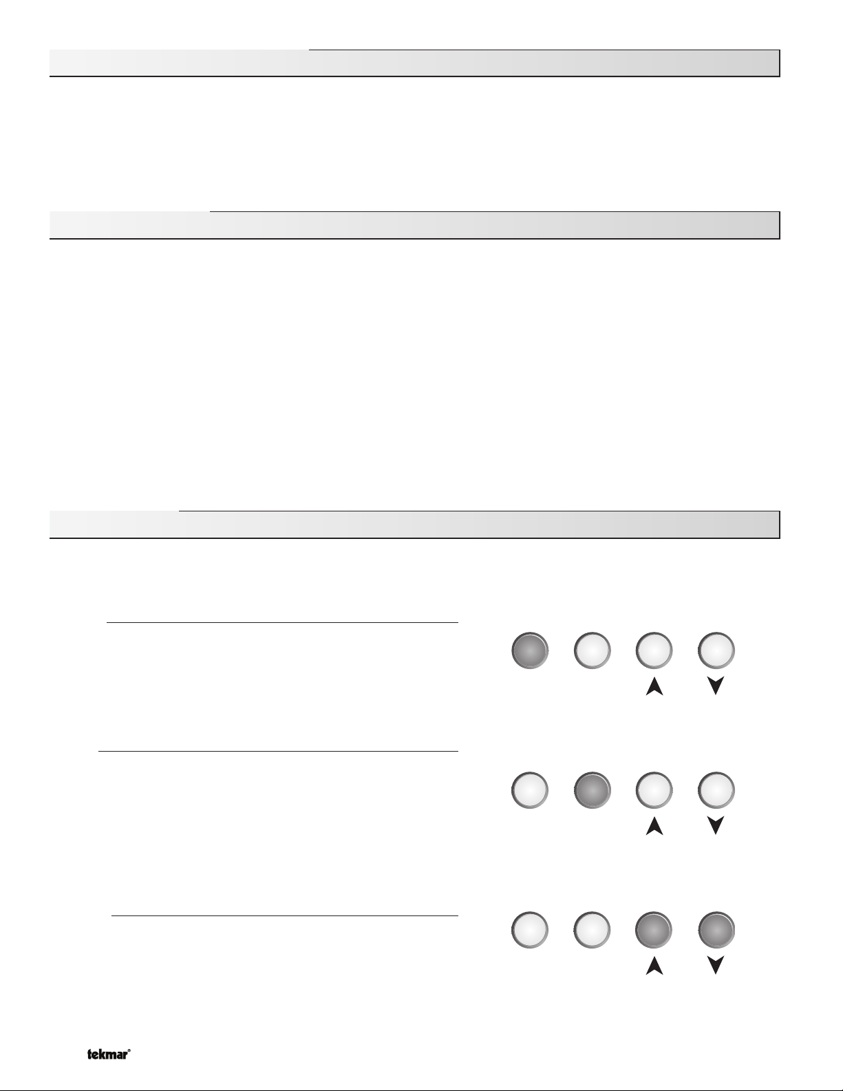
The control uses a Liquid Crystal Display (LCD) as the method of supplying information. You use the LCD in order to setup and
monitor the operation of your system. The control has four push buttons ( Menu, Item,
you program your control, record your settings in the ADJUST menu table which is found in the second half of this brochure.
Menu
All of the items displayed by the control are organized into two menus.
These menus are listed on the top left hand side of the display (Menu
Field). To select a menu, use the Menu button. By pressing and
releasing the Menu button, the display switches between the two
menus. Once a menu is selected, there will be a group of items that
can be viewed within the menu.
▲, ▼) for selecting and adjusting settings. As
Menu Item
Item
The abbreviated name of the selected item will be displayed in the
item field of the display. To view the next available item, press and
release the Item button. Once you have reached the last available
item in a menu, pressing and releasing the Item button will return the
display to the first item in the selected menu.
The items can be quickly scrolled through by holding the Item button
and pressing the
reverse order, hold the Item button and press the
▼ button. To rapidly scroll through the items in the
▲ Button.
Menu Item
Adjust
To make an adjustment to a setting in the control, begin by selecting
the ADJUST menu using the Menu button. Then select the desired
item using the Item button. Finally, use the
make the adjustment.
Additional information can be gained by observing the Status field of the LCD. The status field will indicate which of the control’s
outputs are currently active. Most symbols in the status field are only visible when the VIEW menu is selected.
© 2010 D 268 - 11/10 2 of 32
▲, and / or ▼ button to
Menu Item
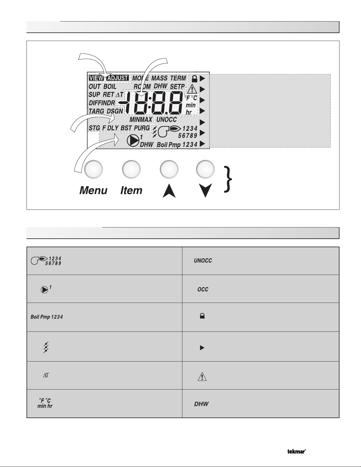
Display
Menu Field
Displays the
current menu
Item Field
Displays an
abbreviated
name of the
selected item
Status Field
Displays the
current status
of the control's
inputs, outputs
and operation
Number Field
Displays the current value of the selected item
Boiler Demand
DHW / Setpoint Demand
WWSD
Priority Override
External Input Signal
Offset
Buttons
Selects Menus, Items
and adjust settings
Symbol Description
Stage
Displays which stage relays are turned on.
Primary Pump
Displays when the primary pump relay is
turned on.
Boiler Pump
Displays which boiler pump relays are
turned on.
Combustion Air Damper
Displays when the Combustion Air Damper
relay is turned on.
Delta T
The current difference between the supply
and return temperatures.
°F, °C, min, hr
Units of measurement.
UnOccupied Schedule
Displays when the control is in UnOccupied
Mode.
Occupied Schedule
Displays when the control is in Occupied
Mode.
Installer Access Level
Displays when the Installer / Advanced Dip
switch is set to Installer
Pointer
Displays the control operation as indicated
by the text.
Warning / Alert
Displays when an error exists or the alert
relay is turned on.
DHW
Displays when the DHW relay is turned on.
3 of 32 © 2010 D 268 - 11/10
Definitions
The following defined terms and symbols are used throughout this manual to bring attention to the presence of hazards of various risk
levels, or to important information concerning the life of the product.
- Warning Symbol: Indicates presence of hazards which can cause severe personal injury, death or
substantial property damage if ignored.
INSTALLATION
CATEGORY II
- Double insulated
- Local level, appliances
Sequence Of Operation
Section A
General
Operation
Page 4 - 6
Section G
External
Input
Page 16 - 17
Section B
Staging
Page 6 - 8
Section C
Pump
Operation
Page 8 - 9
Section D
Boiler Reset
(Stand Alone)
Page 9 - 11
Section E
DHW
Page 12 - 14
Section F
Setpoint
Page 15 - 15
Section A: General Operation
POWERING UP THE CONTROL
When the control is powered up, all segments in the LCD are turned on for 2 seconds. Next, the control displays the control type
number in the LCD for 2 seconds. Next, the software version is displayed for 2 seconds. Finally, the control enters into the normal
operating mode.
OPERATION
The control operates up to nine on / off heat sources to control the supply water temperature to a hydronic system. The
supply water temperature is based on either the current outdoor temperature, an external 0 - 10 V (dc) or 2 - 10 V (dc) signal,
or a fixed setpoint.
Boiler Reset (Stand Alone)
When a boiler demand signal from the heating system is present, the control operates
the boiler(s) to maintain a supply temperature based on the outdoor air temperature and
Characterized Heating Curve settings.
Domestic Hot Water
When a DHW demand signal from a DHW aquastat is present, the control operates the
boiler(s) to maintain the supply water temperature at least as hot as the DHW XCHG
setting. Refer to section E.
Terminal UnitTerminal Unit
Indoor DesignIndoor Design Outdoor DesignOutdoor Design
Design SupplyDesign Supply
Setpoint
When a setpoint demand signal from a setpoint system is present, the control operates
the boiler(s) to maintain the supply water temperature at least as hot as the SETP setting.
Refer to section F.
Decreasing Outdoor Temperature
External Input 0 - 10 V (dc) or 2 - 10 V (dc)
When an external input signal is present, the control converts the signal to a target supply temperature. The control operates the
boiler(s) to maintain the required supply water temperature.
Increasing Water Temperature
© 2010 D 268 - 11/10 4 of 32
SETBACK (UNOCCUPIED)
To provide greater energy savings, the control has a setback feature. With setback, the
supply water temperature in the system is reduced when the building is unoccupied. By
Com
2
1
Boil
Boil
Ret
Sup
5
4
3
UnO
Out
Sw
reducing the supply water temperature, the air temperature in the space may be reduced
even when thermostat(s) are not turned down. Any time the UnO Sw (5) and the Com – (1) ar e
shorted together, the control operates in the UnOccupied mode. When in the UnOccupied
mode, the UNOCC segment is displayed in the LCD. The control adjusts the supply water
temperature based on the UNOCC settings made in the control. This feature has no effect
when the control is used in the External Input mode.
Timer Switch
COMBUSTION AIR OR ALERT CONTACT
The control has an isolated contact that can be used as either a combustion air damper contact or an alert contact. This selection
is made using the C. A. / Alert DIP switch.
Combustion Air (C. A.)
When the DIP switch is set to C. A., terminals 12 and 13 can be used as a switch to operate a combustion air damper. This contact
closes prior to the first stage operating on the control. The amount of time that the contact closes prior to the first stage operating
is set using the combustion delay setting.
The combustion air contact remains closed for a minimum of 15 seconds after the last stage is turned off.
Alert
When the DIP switch is set to Alert, terminals 12 and 13 can be used as a switch to operate an alert circuit. This contact closes
whenever an error message is present on the control. When the alert contact is activated, refer to the Error Messages section of
this brochure to determine the cause of the alert. Once the fault has been fixed, the alert can be cleared by pressing either the
Menu, Item,
▲ or ▼ button.
Boiler Alert
The control can monitor the boiler supply temperature and provide an alert if the temperature does not increase within a certain
amount of time. The amount of time can be set using the Boiler Alert setting. This alert can be used to determine if the boilers
have failed to fire. To reset the alert, press and hold the
▲ and ▼ buttons for 5 seconds while in the VIEW menu.
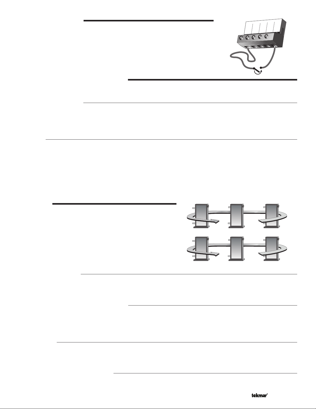
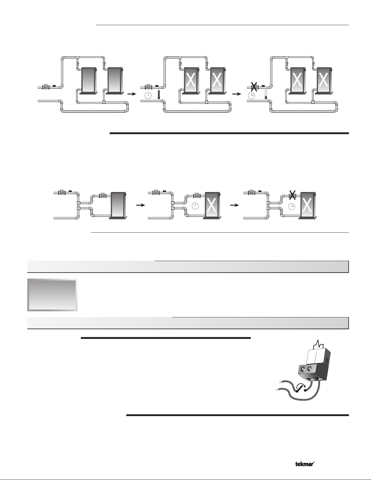
ROTATION
The control’s Equal Run Time Rotation function is fixed at 48 hours. The
firing order of the boilers changes whenever one boiler accumulates 48
hours more running time than any other boiler. After each rotation, the
boiler with the least running hours is the first to fire and the boiler with
the most running hours is the last to fire. This function ensures that all of
the boilers that are being rotated receive equal amounts of use. When
the Rotate / Off DIP switch is set to the Off position, the firing sequence
always begins with lowest boiler to the highest boiler.
1 2 3
720 hours 690 hours 672 hours
3 2 1
672 hours 690 hours 720 hours
Fixed Lead Rotation
In some applications, it may be desirable to have the first boiler fire first at all times while the firing sequence of the remaining
boilers is changed using Equal Run Time Rotation. This rotation option is selected by setting the Fixed Lead / Off DIP switch to
the Fixed Lead position.
First On / Last Off or First On / First Off
When using the Fixed Lead rotation option, a selection must be made between First On / Last Off and First On / First Off
using the DIP switch. When First On / Last Off is selected, the lead boiler is always staged on first and staged off last. When
First On / First Off is selected, the lead boiler is always staged on first and staged off first. This DIP switch is only read by the
control when the Fixed Lead / Off DIP switch is set to Fixed Lead.
Fixed Last
In some applications, it may be desirable to have the last boiler fire last at all times while the firing sequence of the remaining
boilers is changed using Equal Run Time Rotation. This rotation option is selected by setting the Fixed Last / Off DIP switch to
Fixed Last. With a fixed last rotation, the last boiler is the last to stage on and the first to stage off.
Resetting the Rotation Sequence
To reset the rotation sequence, set the Rotate / Off DIP switch to the Off setting for 5 seconds and then return the DIP switch to
the Rotate setting.
5 of 32 © 2010 D 268 - 11/10

RUNNING TIMES
The control displays the accumulated running time of each boiler in the VIEW menu. When using a multi-stage boiler, the running
time that is displayed is the total number of running hours of the Lo stage of the boiler.
Resetting the Running Times
To reset the running time for each boiler, select the appropriate running time in the VIEW menu. Next press the ▲ and ▼ buttons
simultaneously until CLR is displayed.
EXERCISING
The control has a built-in exercising feature that is selected through the Exercise / Off DIP switch. To enable the exercising feature set
the Exercise / Off DIP switch to Exercise. If exercising is enabled, the control ensures that each pump is operated at least once every
3 days. If a pump has not been operated at least once every 3 days, the control turns on the output for 10 seconds. This minimizes
the possibility of the pump seizing during a long period of inactivity. While the control is exercising, the Test LED flashes quickly.
Note: The exercising function does not work if power to the control or pumps is disconnected.
RELOADING FACTORY DEFAULTS
To reload the factory defaults, power down the control for 10 seconds. Power up the control while simultaneously holding the
Menu and
▼ buttons. The control will now display the E01 error message. To clear this error message, follow the procedure in the
Error Messages section of this brochure.
BOILER MINIMUM
The boiler minimum is the lowest temperature that the control is allowed to use as a boiler target temperature. During mild conditions,
if the control calculates a boiler target temperature that is below the BOIL MIN setting, the boiler target temperature is adjusted to at
least the BOIL MIN setting. During this condition, if the boiler(s) is operating, the minimum segment is turned on in the display when
viewing either the boiler supply temperature or the boiler target temperature. Set the BOIL MIN setting to the boiler manufacturer’s
recommended temperature.
BOILER MAXIMUM
The boiler maximum is the highest temperature that the control is allowed to use as a boiler target temperature. If the control does
target the BOIL MAX setting, and the boiler temperature is near the boiler maximum temperature, the maximum segment will be
displayed in the LCD while either the boiler target temperature or the boiler supply temperature is being viewed. At no time does
the control operate the boiler(s) above 248°F (120°C).
Section B: Staging Operation
Section B1
Staging
Section B1: Staging
MODE
The control is capable of staging single stage, two stage, three stage or four stage on / off heat sources. As well, in certain modes
of operation, the control is capable of controlling the individual boiler pumps. The control has 8 modes of operation based on the
type of staging and pump operation that is desired. The following describes the modes of operation.
Mode 1: 9 Single Stage Boilers and a primary pump.
Mode 2: 4 Single Stage Boilers with individual boiler pumps and a primary pump.
Mode 3: 4 Lo/Hi boilers and a primary pump.
Mode 4: 3 Lo/Hi boilers with individual boiler pumps and a primary pump.
Mode 5: 3 Three Stage Boilers and a primary pump.
Mode 6: 2 Three Stage Boilers with individual boiler pumps and a primary pump.
Mode 7: 2 Four Stage Boilers and a primary pump.
Mode 8: 1 Four Stage Boiler with a boiler pump and a primary pump.
Primary
Pump
Supply
Sensor
Return
Sensor
Boiler
Pumps
© 2010 D 268 - 11/10 6 of 32
RELAY 1 RELAY 2 RELAY 3 RELAY 4 RELAY 5 RELAY 6 RELAY 7 RELAY 8 RELAY 9
MODE 1
MODE 2
MODE 3
MODE 4
MODE 5
MODE 6
MODE 7
MODE 8
Boiler 1
Boiler 1
Boiler 1
Stage 1
Boiler 1
Stage 1
Boiler 1
Stage 1
Boiler 1
Stage 1
Boiler 1
Stage 1
Boiler 1
Stage 1
Boiler 2
Boiler 1
Pump
Boiler 1
Stage 2
Boiler 1
Stage 2
Boiler 1
Stage 2
Boiler 1
Stage 2
Boiler 1
Stage 2
Boiler 1
Stage 2
Boiler 3
Boiler 2
Boiler 2
Stage 1
Boiler 1
Pump
Boiler 1
Stage 3
Boiler 1
Stage 3
Boiler 1
Stage 3
Boiler 1
Stage 3
Boiler 4
Boiler 2
Pump
Boiler 2
Stage 2
Boiler 2
Stage 1
Boiler 2
Stage 1
Boiler 1
Pump
Boiler 1
Stage 4
Boiler 1
Stage 4
Boiler 5
Boiler 3
Boiler 3
Stage 1
Boiler 2
Stage 2
Boiler 2
Stage 2
Boiler 2
Stage 1
Boiler 2
Stage 1
Boiler 1
Pump
Boiler 6
Boiler 3
Pump
Boiler 3
Stage 2
Boiler 2
Pump
Boiler 2
Stage 3
Boiler 2
Stage 2
Boiler 2
Stage 2
– – –
Boiler 7
Boiler 4
Boiler 4
Stage 1
Boiler 3
Stage 1
Boiler 3
Stage 1
Boiler 2
Stage 3
Boiler 2
Stage 3
– – –
Boiler 8
Boiler 4
Pump
Boiler 4
Stage 2
Boiler 3
Stage 2
Boiler 3
Stage 2
Boiler 2
Pump
Boiler 2
Stage 4
– – –
Boiler 9
– – –
– – –
Boiler 3
Pump
Boiler 3
Stage 3
– – –
– – –
– – –
LO / HI OR LO / LO
When using multi-stage boilers, a selection must be made regarding the staging order of the boiler(s). This adjustment is made in
the ADJUST menu of the control.
Lo / Hi
If the Lo/Hi staging option is selected the control stages in sequence all of the stages in a single boiler. Once all of the stages are
turned on, the control then stages in sequence all of the stages in the next boiler in the rotation sequence.
Lo / Lo
If the Lo/Lo staging option is selected, the control stages all of the Lo stage outputs in all of the boilers first. Once all of the boilers
are operating on their Lo stages, the control then operates the second stage in each boiler in the same order.
STAGING
The control operates up to nine stages in order to supply the required temperature. After a stage is turned on in the firing sequence,
the control waits for the minimum time delay. After the minimum time delay between stages has expired, the control examines the
control error to determine when the next stage is to fire. The control error is determined using Proportional, Integral and Derivative
(PID) logic.
Proportional compares the actual supply temperature to the boiler target temperature. The colder the supply water temperature,
the sooner the next stage is turned on.
Integral compares the actual supply temperature to the boiler target temperature over a period of time.
Derivative compares how fast or slow the supply water temperature is changing. If the supply temperature is increasing slowly,
the next stage is turned on sooner. If the supply temperature is increasing quickly, the next stage is turned on later,
if at all.
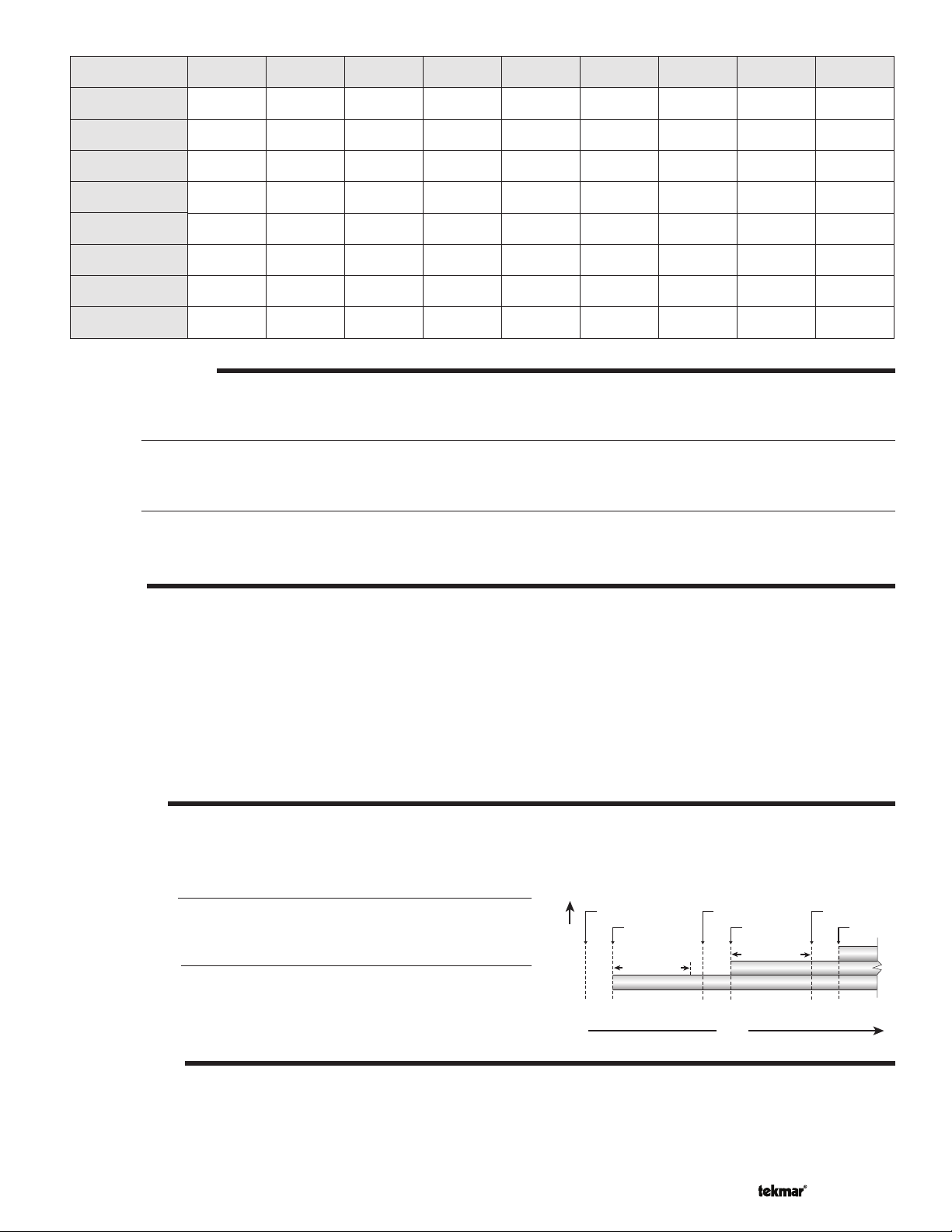
FIRE DELAY
The Fire Delay is the time delay that occurs between the time that the control closes a stage contact to fire a stage and the burner
fires for that stage. The fire delays for the first and third stages in a boiler are adjustable using the F DLY 1 and F DLY 2 settings.
The fire delay for the second and the fourth stages is fixed at 10 seconds.
Fire Delay 1
Fire Delay 1 is available in all modes of operation. Fire Delay 1 is the
fire delay of the first stage of the boiler.
Fire Delay 2
Fire Delay 2 is only available in the modes of operation for Three and Four
Stage Boilers. Fire Delay 2 is the fire delay of the third stage of the boiler.
Stage 1
Contact Closes
Fire
Delay 1
Boiler Temperature
Stage 1
Fires
Interstage Delay
Stage 2
Contact Closes
10
Seconds
Time
Stage 2
Fires
Interstage Delay
Stage 3
Contact Closes
Fire
Delay 2
Stage 3
Fires
STAGE DELAY
The stage delay is the minimum time delay between the firing of stages. After this delay has expired the control can fire the next
stage if it is required. This setting can be adjusted manually or set to an automatic setting. When the automatic setting is used, the
control determines the best stage delay based on the operation of the system.
7 of 32 © 2010 D 268 - 11/10
BOILER MASS
The BOIL MASS setting allows the installer to adjust the control to the thermal mass of the type of heat sources used in the
application. The BOIL MASS setting also adjusts the minimum inter-stage delay time when operating with an automatic differential.
Lo (1)
The Lo setting is selected if the boiler(s) that is used has a low thermal mass. This means that the boiler(s) has a very small water
content and has very little metal in the heat exchanger. A boiler that has a low thermal mass comes up to temperature quite rapidly
when fired. This is typical of many copper fin-tube boilers. The Lo MASS setting provides the quickest staging on of boilers.
Med (2)
The Med setting is selected if the boiler(s) that is used has a medium thermal mass. This means that the boiler(s) either has a
large water content and a low metal content or a low water content and a high metal content. This is typical of many modern
residential cast iron boilers or steel tube boilers. The Med MASS setting stages on additional boilers at a slower rate than the
Lo MASS setting.
Hi (3)
The Hi setting is selected if the boiler(s) that is used has a high thermal mass. This means that the boiler(s) has both a large water
content and a large metal content. A boiler that has a high thermal mass is relatively slow in coming up to temperature. This is
typical of many commercial cast iron and steel tube boilers. The HI MASS setting stages on additional boilers at the slowest rate.
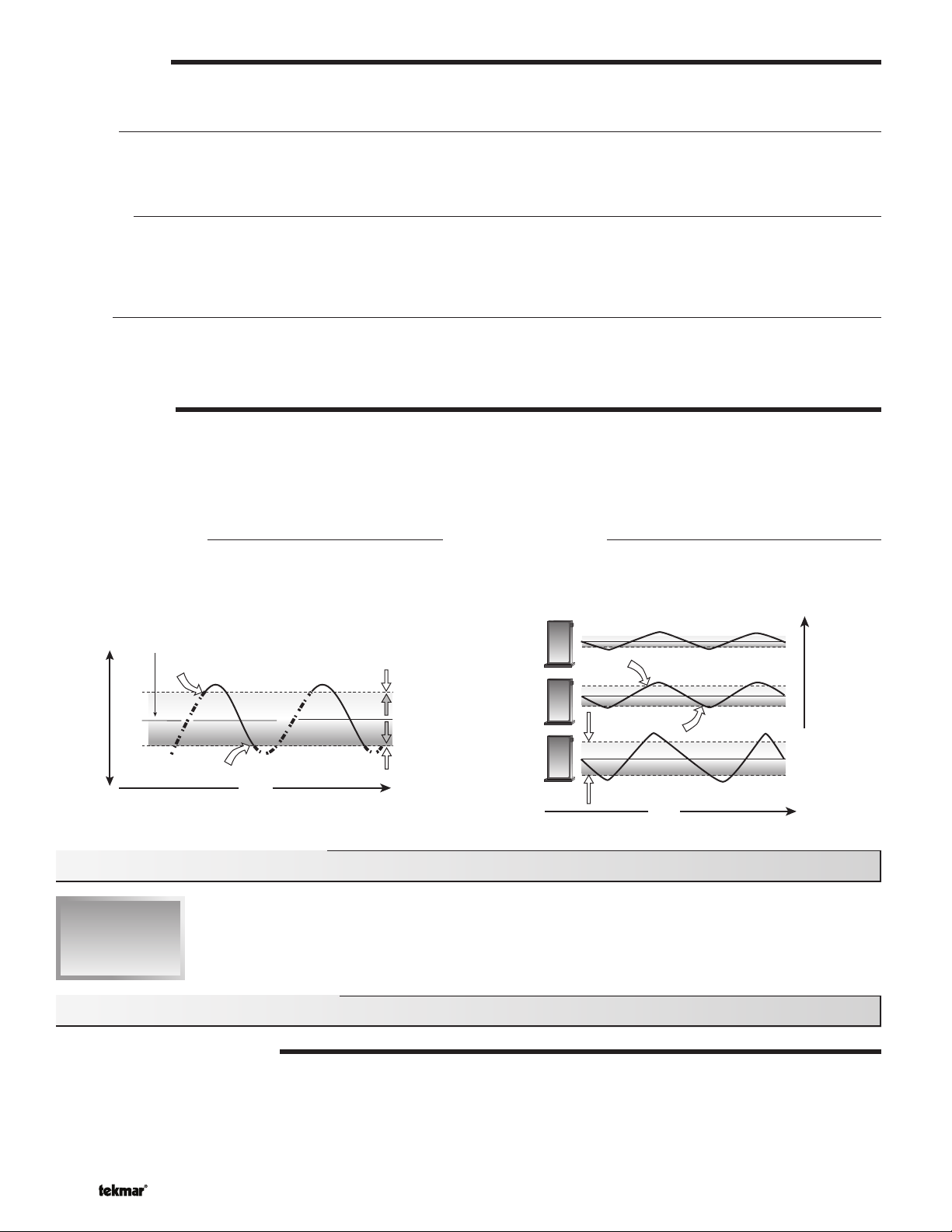
DIFFERENTIAL
An on / off heat source must be operated with a differential in order to prevent short cycling. With the control, either a fixed or an
auto differential may be selected. The boiler differential is divided around the boiler target temperature. The first stage contact
closes when the supply water temperature is ½ of the differential setting below the boiler target temperature. Additional stages
operate if the first stage is unable to bring the supply water temperature up to the boiler target temperature at a reasonable rate. As
the supply temperature reaches ½ of the differential above the boiler target temperature, stages are staged off.
Fixed Differential
If the user desires to have a fixed differential, this is set
using the BOIL DIFF setting in the ADJUST menu.
Desired temperature
Cooler Temperature Warmer
160°F (71°C)
Boiler Off
Boiler On
165°F (74°C)
Time
e
p
m
e
T
e
s
i
r
e
r
u
t
a
r
155°F (68°C)
T
e
m
p
Differential
10°F (6°C)
e
r
a
t
u
r
e
f
a
l
l
Section C: Pump Operation
Section C1
Pump
Operation
Auto Differential
If the Auto Differential is selected, the control automatically
determines the best differential as the load changes. This
reduces potential short cycling during light load conditions.
Off
Differential
On
Heating Load
Time
Section C1: Pump Operation
PRIMARY PUMP OPERATION
The primary pump operates under the following conditions:
• The control receives a boiler demand and is not in warm weather shut down (WWSD).
• The control receives a DHW demand when DHW MODE is set to 3 or 4.
• The control receives a setpoint demand and setpoint MODE is set to 3.
© 2010 D 268 - 11/10 8 of 32
Primary Pump Purge
After a demand is removed, the control continues to operate the primary pump for a period of time. The maximum length of time
that the primary pump continues to run is adjustable using the Purge setting. The primary pump continues to run until either the
purging time has elapsed or the boiler supply temperature drops more than a differential below the boiler minimum setting.
OR
BOILER PUMP OPERATION
In certain modes of operation, the control can operate the individual boiler pumps on each boiler in addition to the primary pump.
The boiler pump turns on prior to the boiler firing and continues to run after the boiler is turned off. The amount of time that the boiler
pump turns on prior to the boiler firing is determined by the BOIL MASS setting. If a BOIL MASS of Lo is selected, the boiler pump
turns on 15 seconds prior to the boiler. If a BOIL MASS of Medium is selected, the boiler pump turns on 22 seconds prior to the
boiler. If a BOIL MASS of Hi is selected, the boiler pump turns on 30 seconds prior to the boiler. However, if the control is operating
based on a setpoint demand, the boiler pump turns on 5 seconds prior to the boiler.
Boiler Pump Purge
The amount of time that the boiler pump continues to run after the boiler turns off is adjustable using the boiler pump purge setting
(PURG Boil Pmp).
Section D: Boiler Reset Operation
Section D1
Boiler Reset
(Stand Alone)
Section D1: Boiler Reset (Stand Alone)
BOILER DEMAND
When operating in the stand-alone mode, a boiler demand is required in order for the
control to provide heat to the heating system. A boiler demand is generated by applying
a voltage between 24 and 230 V (ac) across the Boiler Demand and Common Demand
terminals (6 and 7). Once voltage is applied, the Boiler Demand pointer is displayed in
the LCD. If the control is not in WWSD, the control closes the primary pump contact. The
control calculates a boiler target supply temperature based on the outdoor air temperature
and the characterized heating curve settings. The control then fires the boiler(s), if
required, to maintain the target supply temperature. To use the stand alone mode, the
External Input / Stand Alone DIP switch must be set to Stand Alone.
24 to 230 V (ac)
Boil
Dem
7
6
Com
Dem
BOILER TARGET TEMPERATURE
The boiler target temperature is determined from the characterized heating curve settings and the outdoor air temperature. The
control displays the temperature that it is currently trying to maintain as the boiler supply temperature. If the control does not
presently have a requirement for heat, it does not show a boiler target temperature. Instead, “– – –” is displayed in the LCD.
9 of 32 © 2010 D 268 - 11/10
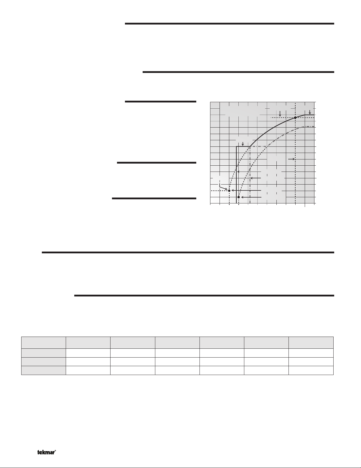
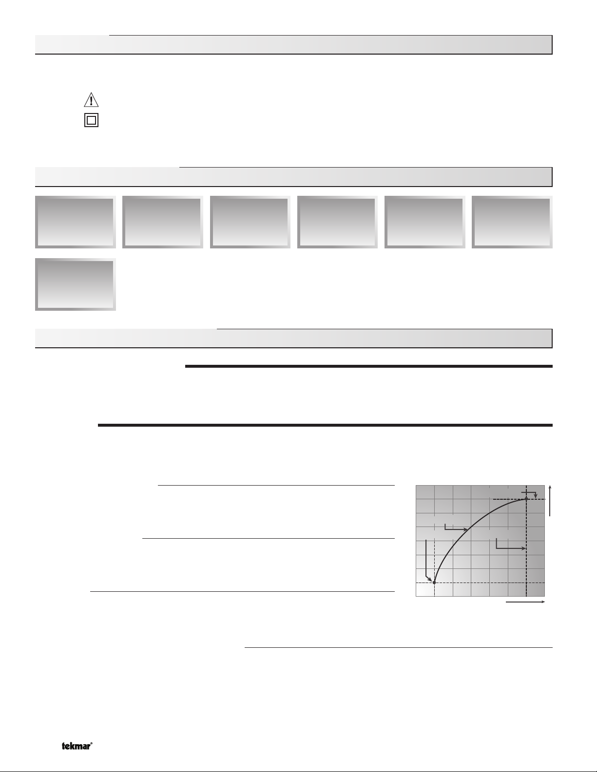
CHARACTERIZED HEATING CURVE
The control varies the supply water temperature based on the outdoor air temperature. The control takes into account the type of
terminal unit that the system is using. Since different types of terminal units transfer heat to a space using different proportions of
radiation, natural convection and forced convection, the supply water temperature must be controlled differently. Once a terminal
unit is selected, the control varies the supply water temperature according to the type of terminal unit. This improves the control
of the air temperature in the building.
BOILER INDOOR DESIGN TEMPERATURE
The indoor design temperature is the room temperature that was used in the original heat loss calculations for the building. This
setting establishes the beginning of the characterized heating curve.
-20
(-29)
210
(99)
190
(88)
170
(77)
150
(66)
130
(54)
110
(43)
90
(32)
70
(2
50°F
(10°C)
OUTDOOR DESIGN TEMPERATURE
The outdoor design temperature is the outdoor air temperature that is the
typical coldest temperature of the year where the building is located. This
temperature is used when doing the heat loss calculations for the building. If
a cold outdoor design temperature is selected, the boiler supply temperature
rises gradually as the outdoor temperature drops. If a warm outdoor design
temperature is selected, the boiler supply temperature rises rapidly as the
outdoor temperature drops.
BOILER DESIGN TEMPERATURE
The design supply temperature is the supply water temperature required
to heat the building when the outdoor air temperature is as cold as the
outdoor design temperature.
WARM WEATHER SHUT DOWN
When the outdoor air temperature rises above the WWSD setting, the
control turns on the WWSD pointer in the display. When the control is in
Warm Weather Shut Down, the boiler demand pointer is displayed if there
Boiler Characterized
Boiler Characterized
Heating Curve
Heating Curve
BOIL MIN
BOIL IND
(27)
80
(16)
60
Outdoor Air Temperature
WWSD Occ
WWSD UnOcc
ROOM Occ
ROOM UnOcc
40
(5)
BOIL DSGN
OUT DSGN
20
(-7)
BOIL MAX
0
(-18)
is a boiler demand. However, the control does not operate the heating
system to satisfy this demand. The control does respond to a DHW or
setpoint demand and operates as described in sections E & F.
ROOM
The room is the desired room temperature for the building and provides a parallel shift of the heating curve. The room temperature
desired by the occupants is often different from the design indoor temperature. If the room temperature is not correct, adjusting
the ROOM setting increase or decreases the amount of heat available to the building. A ROOM setting is available for both the
occupied (day) and unoccupied (night) periods.
Supply Water Temperature
TERMINAL UNITS
The control provides for a selection between six different terminal unit types: two types of radiant floor heat, fancoil, fin-tube convector,
radiator and baseboard. When a terminal unit is selected, the control automatically loads the design supply temperature, maximum
supply temperature, and minimum supply temperature. The factory defaults are listed below. These factory defaults can be changed
to better match the installed system. If a factory default has been changed, refer to section A to reload the factory defaults.
TERMINAL UNIT
BOIL DSGN
BOIL MAX
BOIL MIN
© 2010 D 268 - 11/10 10 of 32
HIGH MASS RADIANT
(1)
120°F (49°C)
140°F (60°C)
OFF
LOW MASS RADIANT
(2)
140°F (60°C)
160°F (71°C)
OFF
FANCOIL
(3)
190°F (88°C)
210°F (99°C)
140°F (60°C)
FIN-TUBE CONVECTOR
(4)
180°F (82°C)
200°F (93°C)
140°F (60°C)
RADIATOR
(5)
160°F (71°C)
180°F (82°C)
140°F (60°C)
BASEBOARD
(6)
150°F (66°C)
170°F (77°C)
140°F (60°C)
 Loading...