


- Data Brochure |
D 664 |
Snow Detector & Melting Control 664 |
07/09 |
|
|
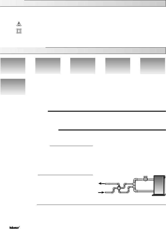
The Snow Detector and Melting Control 664 is designed to control up to two zones in a snow melting system. The control automatically adjusts the mixed supply water to the snow melting system by controlling up to two boilers and a single mixing device. For mixing, the 664 can use a variable speed injection pump, a floating action mixing valve or a 4-20 mA device. The snow melting system may be started manually or automatically through the use of a Snow / Ice Sensor 090. The 664 control includes a large Liquid Crystal Display (LCD) in order to view system status and operating information.
Additional features include: |
|
|
• |
Temporary Idle |
• Cold Weather Cut Out (CWCO) |
• Optional priority zoning operation |
• Remote display and adjustment capabilities |
|
• Slab protection for the snow melting system |
• Test sequence to ensure proper component operation |
|
• |
Boiler protection |
• Pump and valve exercising |
• |
Manual Override |
• CSA C US Certified (approved to applicable UL standards) |
•Adjustable Warm Weather Shut Down (WWSD)
Melt Demand |
|
|
Idle Demand |
|
|
|
|
|
|
Idle Demand |
|
|
Melt Demand |
|
|
|
|
||
WWSD |
|
|
|
|
|
|
|
|
|
Minimum |
|
|
Test |
|
Maximum |
|
|
|
|
|
|
|
|
|
% |
|
|
|
|
Water |
|
|
off |
not testing |
Melting |
|
|
red |
testing |
|
|
red |
testing paused |
|
|
|
|
|
|
|
|
|
|
|
|
|
|
|
|
|
|
Start |
Stop |
|
|
|
|
|
|
|
|
|
|
|
|
|
|
|
|
|
|
|
|
|
For maximum heat, |
|||||||
|
|
|
|
|
|
|
|
|
|
|
|
|
|
|
|
|
|
|
|
|
|
|
|
|
|
|
|
|
|
|
|
|
|
|
|
|
|
|
|
|
press and hold Test |
|||
|
|
|
|
|
|
|
|
|
|
|
|
|
|
|
|
|
|
|
|
|
|
|
|
|
|
|
|
|
|
|
|
|
|
|
|
|
|
|
|
|
button for 3 seconds. |
|||
|
|
|
|
|
|
|
|
Menu |
Item |
|
|
|
|
|
|
|
|
|
|
|
|
|
|
|
Made in Canada by |
|
|
|
|
|
|
|
Meets Class B: |
|||||||||||
|
|
|
|
|
|
|
|
|
|
|
|
|
|
|
|
|
|
|
|
|
|
|
|
|
|
|
|
|
|
Canadian ICES |
||||||||||||||
|
|
|
|
|
|
|
|
|
|
|
|
|
|
|
|
|
|
|
|
|
|
|
tekmar Control Systems Ltd. |
|
|
|
|
|
|
|||||||||||||||
|
|
|
|
|
|
|
|
|
|
|
|
|
|
|
|
|
|
|
|
|
|
|
|
|
|
|
|
|
tektra 900-01 |
|
|
|
|
|
|
|
|
|
|
FCC Part 15 |
||||
|
|
|
|
|
|
|
|
|
|
|
|
|
|
|
|
|
|
|
|
|
|
|
|
|
|
|
|
|
Power |
|
|
|
115 V ± 10% 50/60 Hz 600 VA |
|
|
|||||||||
|
|
|
|
|
|
|
|
|
|
|
|
|
|
|
|
|
|
|
|
|
|
|
|
|
|
|
|
|
Relays |
|
|
|
230 V (ac) 5 A 1/6 hp |
|
|
|
|
|||||||
|
|
|
|
|
Snow Detector & Melting Control 664 |
|
|
|
|
|
|
|
|
|
Stage/Zn/P1 Relays |
230 V (ac) 5 A 1/3 hp |
|
|
|
|
||||||||||||||||||||||||
|
|
|
|
|
|
|
|
|
|
|
|
|
|
Var. Pump |
|
|
|
5 A max (LRA), fuse T2.5 A 250V |
|
|||||||||||||||||||||||||
|
|
|
|
|
|
|
|
|
|
|
|
|
|
|
|
|
|
|
|
|
|
|
|
|
|
|
|
|
|
|
|
230 V (ac) 2.4 A max (FLA) |
|
|
|
|||||||||
|
|
|
|
|
Two Zone, Two Stage Boiler, Mixing |
|
|
|
|
|
|
|
|
|
|
|
|
|
|
Demand |
|
|
|
20 to 260 V (ac) 2 VA |
|
|
|
|
||||||||||||||||
|
|
|
|
|
|
|
|
|
|
|
|
|
|
|
|
|
|
|
|
|
|
|
|
|
|
|
|
|
Signal wiring must be rated at least 300 V. |
|
|
|
|
|||||||||||
|
|
|
|
|
|
1 kΩ max |
|
|
|
|
|
|
|
|
|
|
|
|
|
|
|
|
|
|
|
|
|
|
|
|
|
|
|
|
|
|
|
|
|
|||||
|
|
|
|
|
|
|
|
|
|
|
|
|
|
Do not apply power |
|
|
|
|
|
|
|
|
|
|
|
|
|
|
|
|
|
|
|
|
|
|
|
|
||||||
|
|
|
|
|
|
1 |
2 |
3 |
4 |
5 |
|
6 |
7 |
8 |
9 |
10 |
11 |
12 |
13 |
14 |
15 |
16 |
17 |
18 |
|
19 |
|
20 |
21 |
|
22 |
23 |
|
24 |
25 |
26 |
27 |
28 |
29 |
30 |
H1198D |
|||
|
|
|
|
|
|
4-20 mA |
Opn/ |
Pwr |
Cls |
|
Red |
Blk/ |
Blu |
Yel |
Brn/ |
Slab |
Com |
tN2 |
Mix |
Mix |
Com |
Boil |
Out |
|
Melt/Idle |
Stage |
|
Stage |
Zn |
Com |
Zn |
Sys |
Power |
|
|
|||||||||
|
|
|
|
|
|
+ |
– |
Var |
Mix |
|
|
|
Com |
|
|
Slab1 |
2 |
|
|
Ret |
Sup |
|
|
|
|
Demand |
1 |
|
2 |
1 |
Zn |
2 |
P1 |
L |
N |
|
||||||||
|
|
|
|
|
|
|
|
|
|
|
|
|
|
|
|
|
|
|
|
|
|
|
|
|
|
|
|
|
|
|
|
|
|
|
|
|
|
|
|
|
|
|
|
|
|
|
|
|
|
|
|
|
|
|
|
|
|
|
|
|
|
|
|
|
|
|
|
|
|
|
|
|
|
|
|
|
|
|
|
|
|
|
|
|
|
|
|
|
|
|
|
|
|
|
|
|
|
|
|
|
|
|
|
|
|
|
|
|
|
|
|
|
|
|
|
|
|
|
|
|
|
|
|
|
|
|
|
|
|
|
|
|
|
|
Output
4-20 mA OR device 
Output
Variable
Speed
driven
pump
OR
Output
Mixing
Valve &
Actuating
Motor
Input |
|
|
|
|
|
|
|
|
Snow/Ice Sensor |
|
|
|
|
|
|
|
|
090 installed with |
|
|
|
|
|
|
|
|
Sensor Socket |
|
|
|
|
|
|
|
|
091 Optional |
|
|
|
|
|
|
|
|
or |
|
|
|
|
|
|
|
|
Slab |
|
|
OR |
|
|
|
|
|
Sensor |
|
|
|
|
|
|
|
|
|
|
|
|
|
|
|
|
|
Optional |
|
|
|
|
|
|
|
|
Input |
|
|
Input |
Input |
Input |
Input |
Input |
|
Slab |
Remote Display Module (RDM) |
Universal |
Universal |
Universal |
Outdoor |
Input |
||
Sensor |
|
|
or |
Sensor |
Sensor |
Sensor |
Sensor |
Melt/Idle |
Optional |
Remote Start / Stop Module |
Included |
Included |
Included |
Included |
Demand |
||
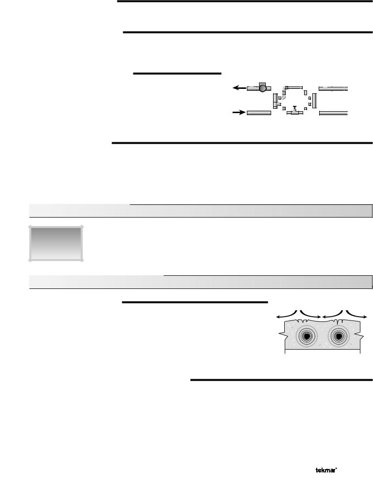
Input
115 V (ac)
Power
Supply
Output
System
Pump
Output
Zone
Pumps
OR OR
M Zone Valves
Output
Boiler
Output
Boiler
1 of 36 |
© 2009 |
D 664 - 07/09 |

How To Use The Data Brochure
This brochure is organized into four main sections. They are: 1) Sequence of Operation, 2) Installation, 3) Control Settings, and 4) Troubleshooting. The Sequence of Operation section has 6 sub-sections. We recommend reading Section A: General of the Sequence of Operation, as this contains important information on the overall operation of the control. Then read to the sub-sections that apply to your installation.
The Control Settings section (starting at DIP Switch Settings) of this brochure describes the various items that are adjusted and displayed by the control. The control functions of each adjustable item are described in the Sequence of Operation.
Table of Contents
User Interface.................................................. |
Pg 2 |
DIP Switch Settings........................................ |
Pg 20 |
Description of Display Elements .................. |
Pg 3 |
Access Levels ................................................. |
Pg 21 |
Sequence of Operation .................................. |
Pg 4 |
Control Settings.............................................. |
Pg 22 |
Section A: General Operation .............. |
Pg 4 |
View Menu .............................................. |
Pg 22 |
Section B: Snow Melting....................... |
Pg 6 |
Adjust Menu ........................................... |
Pg 23 |
Section C: Boiler Operation ................. |
Pg 8 |
Monitor Menu ......................................... |
Pg 26 |
Section D: Melting Enable / Disable .... |
Pg 9 |
Schedule Menu ...................................... |
Pg 28 |
Section E: Melting Operation ............... |
Pg 12 |
Miscellaneous Menu ............................. |
Pg 28 |
Section F: Idling Operation................... |
Pg 14 |
Testing and Troubleshooting ........................ |
Pg 29 |
Installation....................................................... |
Pg 15 |
Error Messages...................................... |
Pg 31 |
Electrical Connections.......................... |
Pg 15 |
Technical Data................................................. |
Pg 36 |
Testing The Wiring................................. |
Pg 18 |
Limited Warranty ............................................ |
Pg 36 |
User Interface
The 664 uses a Liquid Crystal Display (LCD) as the method of supplying information. You use the LCD in order to setup and monitor the operation of your system. The 664 has four push buttons (Menu, Item, ▲, ▼) for selecting and adjusting settings. As you program your control, record your settings in the ADJUST Menu table which is found in the second half of this brochure.
Menu
All of the items displayed by the control are organized into various menus. These menus are listed on the left hand side of the display (Menu Field). To select a menu, use the Menu button. By pressing and releasing the Menu button, the display will advance to the next available menu. Once a menu is selected, there will be a group of items that can be viewed within the menu.
Item
The abbreviated name of the selected item will be displayed in the item field of the display. To view the next available item, press and release the Item button. Once you have reached the last available item in a menu, pressing and releasing the Item button will return the display to the first item in the selected menu.
Adjust
To make an adjustment to a setting in the control, begin by selecting the appropriate menu using the Menu button. Then select the desired item using the Item button. Finally, use the ▲ and / or ▼ button to make the adjustment.
Additional information can be gained by observing the Status field of the LCD. The status field will indicate which of the control’s outputs are currently active. Most symbols in the status field are only visible when the VIEW Menu is selected.
Menu Item
Menu Item
Menu Item
© 2009 |
D 664 - 07/09 |
2 of 36 |

Display
Item Field
Displays an abbreviated name of the selected item
Menu Field
Displays the current menu
Status Field
Displays the current status of the control's inputs, outputs and operation
Number Field
Displays the current value of the selected item
Melt Demand
Idle Demand
WWSD
Minimum
Maximum
Water
Melting
Buttons
Selects Menus, Items and adjust settings
Symbol Description
Open / Close |
Lock / Unlock |
|
Displays when the actuator is opening or |
Displays when the access levels are |
|
closing the mixing valve. |
locked or unlocked. |
|
|
|
|
Mixing Device Output Scale |
Burner |
|
Shows output of injection pump, mixing valve |
||
Displays when the Stage 1 and / or |
||
or 4-20 mA device. Arrows show whether the |
||
Stage 2 relay is turned on. |
||
output is increasing or decreasing. |
||
|
||
Pump |
Pointer |
|
Displays the control operation as |
||
Displays when the system pump is operating. |
||
indicated by the text. |
||
|
||
|
|
|
Override |
°F, °C, min, hr, sec |
|
Displays when the control is in override mode. |
Units of measurement. |
|
|
|
|
Warning |
Zone |
|
Displays when an error exists or when a limit |
||
Displays when a zone is in operation. |
||
has been reached. |
||
|
||
|
|
3 of 36 |
© 2009 |
D 664 - 07/09 |
Definitions
The following defined terms and symbols are used throughout this manual to bring attention to the presence of hazards of various risk levels, or to important information concerning the life of the product.
- Warning Symbol: Indicates presence of hazards which can cause severe personal injury, death or substantial property damage if ignored.
- Double insulated
INSTALLATION
CATEGORY II - Local level, appliances
Sequence of Operation
Section A |
|
Section B |
|
Section C |
|
Section D |
|
|
Section E |
|
General |
|
Snow |
|
Boiler |
|
Melting Enable |
|
|
Melting |
|
Operation |
|
Melting |
|
Operation |
|
/ Disable |
|
|
Operation |
|
Page 4 - 5 |
|
Page 5 - 7 |
|
Page 7 - 9 |
|
Page 9 - 11 |
|
|
Page 12 - 13 |
|
|
|
|
|
|
|
|
|
|
|
|
|
|
|
|
|
|
|
|
|
|
|
Section F |
|
|
|
|
|
|
|
|
|
|
Idling |
|
|
|
|
|
|
|
|
|
|
Operation |
|
|
|
|
|
|
|
|
|
|
Page 14 |
|
|
|
|
|
|
|
|
|
|
|
|
|
|
|
|
|
|
|
|
|
Section A: General Operation
POWERING UP THE CONTROL
When the Snow Detector and Melting Control 664 is powered up, the control displays all LCD segments for 2 seconds, then the control type number in the LCD for 2 seconds. Next, the software version is displayed for 2 seconds. Finally, the control enters into the normal Operating mode and the LCD defaults to displaying the current outdoor air temperature.
MIXING DEVICE SELECTION (MIXING)
The 664 can supply a lower fluid temperature to the snow melting system by using a variable speed injection pump, a floating action mixing valve or a modulating 4-20 mA device. The selection is made under the Mixing item in the ADJUST menu.
Variable Speed Injection (VAR)
A standard wet rotor circulator is connected to the 664 on the Pwr Mix and Opn / Var terminals (4 and 3). The 664 increases or decreases the power output to the circulator based on the system requirements. For correct sizing and piping of the variable speed injection pump, refer to Essay E 021. A visual indication of the current variable speed output is displayed in the LCD in the form of a segmented bar graph.
Floating Action (FLOT)
A floating action motor is connected to the 664 on the Pwr Mix, Opn / Var and Cls terminals (4, 3 and 5). The 664 pulses the actuator motor open or close based on the system requirements. The mixing valve that the actuator is connected to can be either a 2-way, 3-way or 4-way valve. A visual indication of the current position of the valve is displayed in the LCD in the form of a segmented bar graph.
4-20 mA Output (4-20)
A 4-20 mA device is connected to the 664 on the 4-20 mA + and 4-20 mA – terminals (1 and 2). The 664 increases or decreases the modulating output to the 4-20 mA device based on the system requirements. The 4-20 mA output can be used to operate a variety of actuating motors for mixing valves and motor drives for larger pumps. A visual indication of the current output of the 4-20 mA device is displayed in the LCD in the form of a segmented bar graph.
© 2009 |
D 664 - 07/09 |
4 of 36 |
MIXING TARGET (MIX TRG)
The mixing target temperature is the supply fluid temperature calculated by the control. The control will operate the snow melt system so that the mix supply temperature reaches the mixing target except while providing boiler return protection for the boiler.
MIXING MAXIMUM (MIX MAX)
The Mix Max sets the highest fluid temperature that the control is allowed to calculate as the mixing target temperature. If the control does target the Mix Max setting, and the mix supply temperature is near the MIX MAX, the Maximum pointer is displayed in the LCD while the MIX SUP temperature is being viewed.
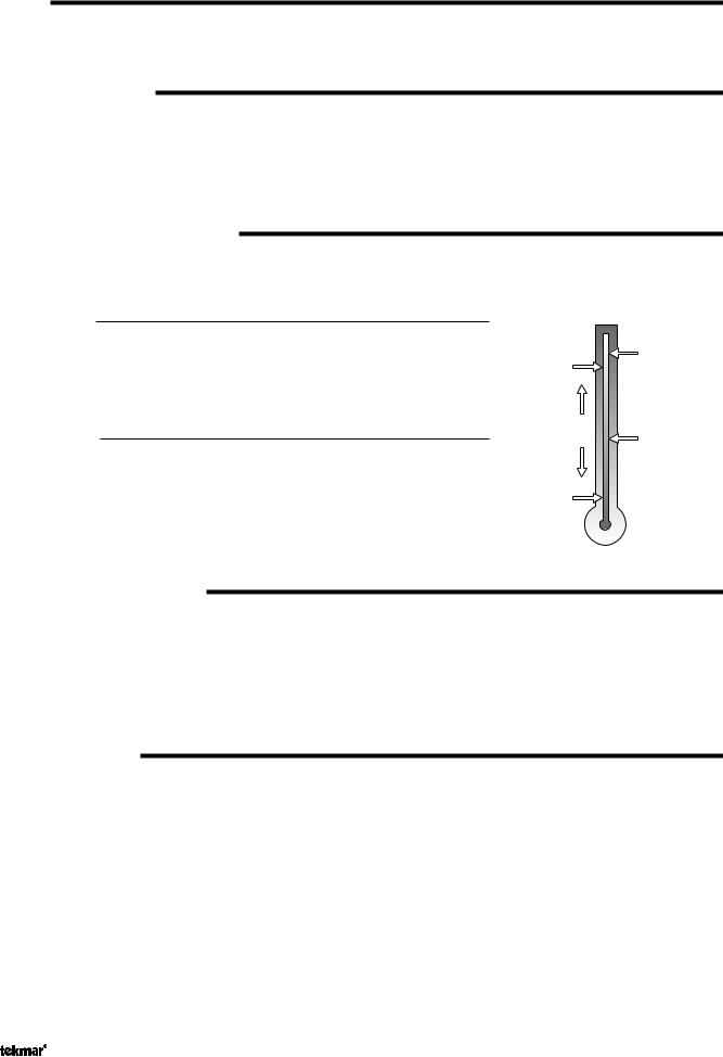
BOILER PROTECTION (Boil MIN)
The 664 is capable of providing boiler protection from cold mixing system return fluid temperatures. If the boiler sensor temperature is cooler than the Boil Min setting while the boiler(s) is firing, the 664 reduces the output from the mixing device. This limits the amount of cool return water to the boiler(s) and allows the boiler temperature to recover. This feature can only be used if the Boil Sens item is set to Sup or Ret. The 664 can not provide boiler protection if the Boil Sens item is set to None.
Mixing
Sensor
Boiler Supply |
Sensor |
OR |
Boiler Return |
Sensor |
EXERCISING (EXERCISE)
The 664 has a built in pump and valve exercising function. The exercising period is adjustable and is factory set at 70 hours. If a pump or valve output has not been operated at least once during every exercising period, the control turns on the output for 10 seconds. This minimizes the possibility of a pump or valve seizing during a long period of inactivity. In the case where a mixing valve is being used as the mixing device, the 664 ensures that the valve operates over its entire range at least once each exercising period.
Note: The exercising function does not work if power to the control, valves or pumps is disconnected.
Section B: Snow Melting
Section B1
General
Snow Melting
Section B1: General Snow Melting
SLAB PROTECTION ( T MAX)
tensile stresses
The control can limit the rate at which heat is applied to the currently operating zone through the T Max setting. The ΔT (delta T) is the temperature difference between the snow melting supply temperature and the snow melting return temperature. By limiting this temperature difference, the rate at which heat is applied to the currently operating zone can be controlled and thermal stresses in the slab can be minimized. When the control is operating at the ΔT MAX, the Maximum pointer can be seen when viewing the ΔT item in the VIEW menu. The control provides slab protection differently based on boiler sensor placement.
Note: The ΔT MAX function is only available if the PRIORITY item is set to COND or FULL.
VISCOSITY COMPENSATION (EXCEEDING T MAX)
At low temperatures, the glycol solutions used in snow melting systems become very viscous and difficult to pump. In order to overcome this condition during a cold start of a snow melting system, the 664 is allowed to exceed the T Max setting for a period of time in order to warm the glycol solution. This allows the control to compensate for the high viscosity of the glycol solution and is used when the mixing return temperature is below 30°F (-1°C). When the control exceeds the T Max setting, the Maximum pointer will flash when viewing the ΔT item in the VIEW menu.
Note: This operation only occurs if the PRIORITY item is set to COND or FULL.
5 of 36 |
© 2009 |
D 664 - 07/09 |
SOFT START
When the control starts applying heat to the slab, the supply temperature to the snow melting system is ramped up over a period of time until it reaches the target mixed supply temperature. This feature helps reduce thermal stresses in the slab.
Note: This operation only occurs if the Boil SENS item is set to RET or NONE.
RUNNING TIME (RUN TIME)
The running time is the length of time that a zone operates once it has reached its slab target temperature. During the time that a zone is approaching its slab target temperature, the Run Time does not decrease. Once a zone reaches its slab target temperature the Run Time begins counting down. When the Run Time reaches 0:00 as displayed in the Status item of the appropriate zone in the VIEW menu, the zone has finished melting.
Note: The running time is only applicable when a manual melting enable signal starts the snow melting system. Refer to Section D1 for a description of a manual melting enable.
WARM WEATHER SHUT DOWN (WWSD)
The control has a warm weather shut down for each zone that prevents the control from entering the Melt or Idle modes in order to conserve energy. While a zone is in WWSD, the word WWSD is displayed in the STATUS 1 or STATUS 2 items in the VIEW menu. When both zones enter WWSD, the 664 turns on the WWSD pointer in the display.
Automatic (Auto)
There is a warm weather shut down for each zone. When both the slab temperature of a zone and the outdoor temperature exceed the zone’s Melt Temperature setting by more than 2°F (1°C), the zone enters into WWSD. While a zone is in WWSD, the word WWSD is displayed in the STATUS item of the appropriate zone in the VIEW menu. When both zones enter WWSD, the 664 turns on the WWSD pointer in the display.
Adjustable WWSD
When the WWSD is set to a temperature, the WWSD occurs when the outdoor air temperature exceeds the WWSD setting by 1°F (0.5°C) and when the slab temperature of a zone exceeds 34°F (1°C). The zone exits WWSD when the outdoor air temperature falls 1°F (0.5°C) below the WWSD setting or if the slab temperature of the zone falls below 34°F (1°C). This allows the Melting Temperature setting to be set higher than the WWSD. This is useful where high slab temperatures are required to melt the snow or ice. A good example of this is installations using paving bricks on top of sand and concrete layers.
COLD WEATHER CUT OUT (CWCO)
Outdoor |
Slab |
|
Temperature |
Temperature |
|
|
MELT |
|
WWSD |
|
|
Control enters |
|
|
Idle and waits |
IDLE |
|
for Melt Enable |
||
|
||
CWCO |
|
Maintaining the zone(s) at either the melting or idling temperature during extremely cold temperatures can be expensive or impossible. The control turns the snow melting system off when the outdoor air temperature drops below the Cold Weather Cut Out (CWCO) temperature. While the control is in CWCO, the word CWCO is displayed in the STATUS 1 and STATUS 2 item in the VIEW menu. If a Snow / Ice Sensor 090 is used, the heater in the sensor is kept on during CWCO until the control detects moisture. If water is detected, the heater is turned off but the control retains the moisture detected information. When the outdoor temperature rises above the CWCO temperature, the control exits CWCO and if the Snow / Ice Sensor 090 detected moisture during CWCO, the control initiates Melting mode. If the control has been started prior to the CWCO, it resumes the Melting mode once the outdoor air temperature rises above the CWCO temperature.
STATUS 1 and 2 (STATUS)
While in the VIEW menu there are a number of items available to determine the current status of zone 1 and zone 2. To view the current status of zone 1, select the STATUS 1 item in the VIEW menu. To view the current status of zone 2, select the STATUS 2 item in the VIEW menu.
• STRT |
The word STRT is displayed after the snow melting system has been manually enabled. It is displayed until the |
|
zone reaches its slab target temperature. If the zone is at its slab target temperature, STRT is displayed for five |
|
seconds after the snow melting system has started operation. This is to verify that the control has entered into |
|
the Melting mode. |
• STOP |
The word STOP is displayed for five seconds after the snow melting system has been manually disabled. The |
|
word STOP is also displayed if either a Remote Start / Stop Module 039, Remote Display Module 040 or the Stop |
|
on the control stops the snow melting system and an external melt demand is still present. |
• IDLE |
The word IDLE is displayed as long as the zone is operating at its idling temperature. |
• “IDLE” |
The word IDLE is flashed on the display as long as the zone is operating in temporary idle. |
• EXT |
The word EXT is displayed when the RUN TIME has reached 0:00 and the control still has an external melt demand. |
|
In this situation, the zone continues melting until the melt demand is removed or the control is stopped. |
© 2009 |
D 664 - 07/09 |
6 of 36 |
• DET |
The word DET is displayed after the snow melting system has been automatically enabled by the Snow / Ice |
|
Sensor 090 and the zone is at its slab target temperature. DET is also displayed once the control is manually |
|
enabled after automatic detection by the 090 and the running time has counted down to 0:00. |
• 0:00 to 23:59 hr While the zone is up to temperature and melting, the remaining RUN TIME is displayed. |
|
• INF |
If an infinite RUN TIME is selected and the zone is melting, INF is displayed. |
• WWSD |
When the zone is in Warm Weather Shut Down, WWSD is displayed. |
• CWCO |
When the control is in Cold Weather Cut Out, CWCO is displayed. |
BOILER PROTECTION
Refer to Section A for a description of boiler protection.
BOILER OPERATION
Refer to Section C for a description of boiler operation.
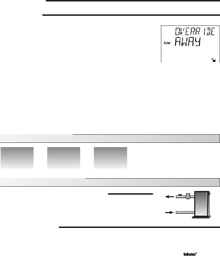
SNOW MELTING OVERRIDE
If the Away setting is selected in the SCHEDULE menu, the snow melting system is shut down. Both the Melting and Idling temperatures are ignored as long as the control remains in the Away mode.
SYSTEM PUMP OPERATION (Sys P1)
The System Pump (Sys P1) contact closes and remains closed as long as at least one of the zones is either in the Melting or Idling mode. The System Pump contact shuts off if the control is in CWCO, if both zones are in WWSD, or if there is no call for Melting or Idling.
ZONE OUTPUTS (Zn 1 and Zn 2)
The Zone 1 (Zn 1) contact and the Zone 2 (Zn 2) contact operate based on the Melting and / or Idling operation. Refer to Melting Section E and / or Idling Section F for a description of how the zone contact(s) operate. The Zone Pump contact(s) shuts off if the control is in CWCO, if the corresponding zone(s) is in WWSD, or if there is no call for Melting or Idling.
PURGE
The system pump (Sys P1) and zoning device(s) (Zn 1 and Zn 2) continue to operate for up to 2 minutes after the last demand is removed. This purges the residual heat from the boiler(s) into the snow melting slab. If the boiler temperature drops below the Boil Min setting after 20 seconds, the purge is aborted and the system pump and zoning device(s) are turned off.
Section C: Boiler Operation
Section C1 |
|
Section C2 |
|
Section C3 |
Boiler Supply |
|
Boiler Return |
|
No Boiler |
Sensor |
|
Sensor |
|
Sensor |
|
|
|
|
|
Section C1: Boiler Supply Sensor
BOILER SENSOR ON THE SUPPLY (Boil SENS = SUP)
When operating a boiler or boiler plant that is dedicated to a snow melting system, the 664 is designed to operate the boiler(s) as efficiently as possible. The boiler(s) are cycled based on the mixing supply fluid temperature. This is to provide longer and more efficient boiler cycles. This mode of operation only works if the Boil SENS item is set to SUP.
BOILER MINIMUM (Boil MIN)
The Boil MIN is the lowest water temperature that the control is allowed to use as a boiler target temperature. If the boiler(s) is operating, and the boiler supply temperature is near the Boil Min setting, the Minimum pointer turns on in the LCD while the Boil SUP temperature is being viewed. If the installed boiler(s) is designed for condensing or low temperature operation, set the Boil MIN adjustment to OFF.
7 of 36 |
© 2009 |
D 664 - 07/09 |
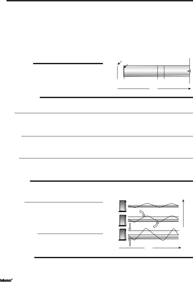
STAGING
The 664 controls up to two stages in order to supply the required temperature. After the first stage is turned on in the firing sequence, the control waits a minimum amount of time before turning on the next stage. After the minimum time delay between stages has expired, the 664 examines the control error to determine when the next stage is to fire. The control error is determined using Proportional, Integral and Derivative (PID) logic.
Proportional – compares the actual temperature to the target temperature. The colder the temperature, the sooner the next stage is turned on.
Integral – compares the actual temperature to the target temperature over a period of time.
Derivative – determines how fast or slow the actual temperature is changing. If the temperature is increasing slowly, the next stage is turned on sooner. If the temperature is increasing quickly, the next stage is turned on later, if at all.
– Each stage has a minimum on time, and a minimum off time.
FIRE DELAY (FIRE DLY)
The FIRE DLY is the delay time that may occur between the time that the 664 closes a stage contact and the burner fires for that stage. This delay is usually the result of burner pre-purge or other forms of time delay built into the burner’s safety circuits.
Boiler Contact Closes
|
Boiler Fires |
|
|
|
|
Minimum |
|
|
Minimum |
|
Minimum |
|
||
|
On Time |
Off Time |
|
On Time |
|
|
|
|
|
Fire |
|
Fire |
||
Delay |
|
Delay |
||
Time
BOILER MASS (Boil MASS)
The Boil MASS setting allows the 664 to adjust to different types of heat sources depending on their thermal mass.
Light (LITE)
The LITE setting is selected if the boiler(s) that is used has a low thermal mass. This means that the boiler(s) has a very small water content and has very little metal in the heat exchanger. A boiler that has a low thermal mass comes up to temperature quite rapidly when fired. This is typical of many copper fin-tube boilers.
Medium (MED)
The MED setting is selected if the boiler(s) that is used has a medium thermal mass. This means that the boiler(s) either has a large water content and a low metal content or a low water content and a high metal content. This is typical of many modern residential cast iron boilers or steel tube boilers.
Heavy (HEVY)
The HEVY setting is selected if the boiler(s) that is used has a high thermal mass. This means that the boiler(s) has both a large water content and a large metal content. A boiler that has a high thermal mass is relatively slow in coming up to temperature. This is typical of many commercial cast iron and steel tube boilers.
DIFFERENTIAL (DIFF)
An on / off heat source such as a boiler must be operated with a differential in order to prevent short cycling. With the 664, either a fixed or an automatic differential may be selected.
Fixed Differential
The differential is centered around the target temperature. If the temperature drops 1/2 the differential below the target temperature, the 664 closes the Boiler contact(s) to fire the boiler(s). If the temperature rises 1/2 of the differential above the target temperature, the 664 opens the Boiler contact(s) to turn off the boiler(s).
Auto Differential (AUTO)
If the AUTO Differential is selected, the 664 automatically adjusts the Differential setting under the current load conditions to avoid short cycling.
STAGE 1 AND 2 (STAGE)
O
Di erential |
On |
|
Time
Heating Load
The Stage 1 and 2 setting may be selected to AUTO or OFF. When AUTO is selected, the stage is activated and the control operates the appropriate boiler. When OFF is selected, the control does not fire the stage.
© 2009 |
D 664 - 07/09 |
8 of 36 |
ROTATION (ROTATE)
The ROTATE item is an adjustable setting that is factory set at 48 hours. The firing order of the boiler changes whenever one stage’s accumulated running time exceeds the other stage’s accumulated running time by more than the ROTATE setting. After each rotation, the stage with the least running hours is the first to fire and the stage with the most running hours is the last to fire. This function ensures that both stages receive equal amounts of use. When this item is set to the OFF setting, Stage 1 is always the first to fire.
Section C2: Boiler Return Sensor
BOILER SENSOR ON THE RETURN (Boil SENS = RET)
The boiler sensor should be located on the boiler return if the 664 is one of many controls that can call for boiler operation. When in the Return mode, the 664 provides a boiler enable through the Stage 1 contact. The 664 no longer tries to control the boiler supply water temperature directly, but allows the boiler to operate at its operating aquastat setting when required. If this mode of operation is selected, the boiler pump should either operate continuously, or be operated in parallel with the System Pump contact (Sys P1). When the mixing device begins to ramp up, the Stage 1 contact closes on the 664. The Stage 1 contact remains closed until the mixing device no longer requires heat. With the sensor on the boiler return, the 664 is still capable of providing boiler protection as described in Section A.
Section C3: No Boiler Sensor
NO BOILER SENSOR (Boil SENS = NONE)
The 664 is capable of operating without a boiler sensor if desired. Without a boiler sensor, the 664 is unable to provide boiler protection. In this mode of operation, the Stage 1 contact is used to provide a boiler enable. When the mixing device begins to ramp up, the Stage 1 contact on the 664 closes. The Stage 1 contact remains closed until the mixing device no longer requires heat. This type of application is typical if the 664 is drawing heat from a source that already incorporates some form of boiler protection.
Section D: Melting Enable / Disable
Section D1
Snow Melting
Enable
Section D2
Snow Melting
Disable
Section D1: Snow Melting Enable
The snow melting system can be enabled manually or automatically. A melting enable signal applied to the control places both zones into the Melting mode. If a melting enable signal is applied once the system is already in the Melting mode, the control responds to the last command received.
MANUAL MELTING ENABLE
A manual melting enable signal requires the user to manually start the snow melting system and can be provided from the Start button on the control, Remote Start / Stop Module 039, Remote Display Module 040, or an external melt demand.
Start Button on the Control
The snow melting system is enabled by pressing the Start button on the control while in the VIEW menu. The control then displays the RUN TIME setting to allow the user to adjust it. Once the snow melting system is enabled, the word STRT is displayed for at least 5 seconds in the STATUS item of the appropriate zone while in the VIEW menu. If the Start button on the control is pressed while the zone(s) is already melting and up to temperature, the running time counter is reset to the RUN TIME setting.
9 of 36 |
© 2009 |
D 664 - 07/09 |

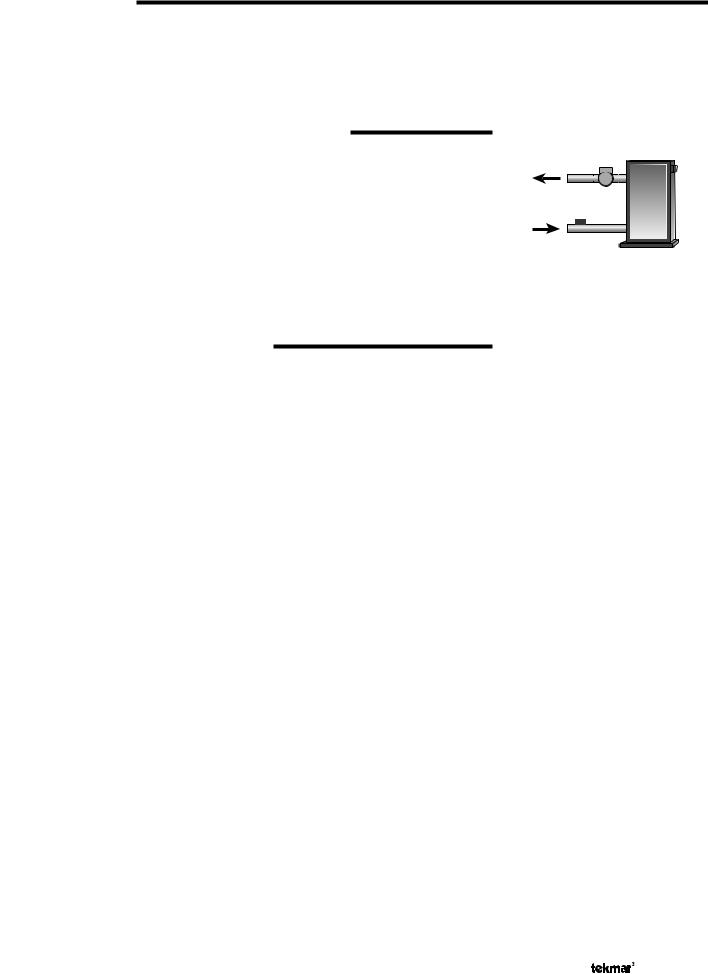
Remote Start / Stop Module 039
The snow melting system is enabled by pressing the button on the front of the 039. While the zone(s) is coming up to temperature, a green indicator light flashes on the front of the 039. Once the zone(s) is up to temperature and the RUN TIME is counting down, the green indicator light on the front of the 039 is on solid.
7
8
9
Start / Stop
Remote Display Module 040
The snow melting system is enabled by pressing the ▲ button on the 040 while in the VIEW menu. The 040 then displays the RUN TIME setting to allow the user to adjust it. Once the snow melting system is enabled, the word STRT is displayed for at least 5 seconds in the Status item of the appropriate zone while in the VIEW menu.
External Melt Demand (DIP switch set to Melt Demand)
The snow melting system is enabled when a voltage between 24 and 240 V (ac) is applied across the Melt / Idle Demand terminals (19 and 20). An external melt demand must be present for at least 4 seconds in order to start the snow melting system. If the RUN TIME reaches 0:00 and the external melt demand is still present, the control continues melting until the external melt demand is removed or the system is otherwise stopped.
Note: This operation only occurs if the Idle Demand / Melt Demand DIP switch is set to the Melt Demand position.
AUTOMATIC MELTING ENABLE (Snow / Ice Sensor 090)
The 664 can use the Snow / Ice Sensor 090 to provide an automatic melting enable signal to start the snow melting system. The control continually monitors the 090 for the presence of moisture. Once moisture is detected, the Water pointer is displayed in the LCD and the snow melting system is enabled.
Note: In addition to the Snow / Ice Sensor 090 connected to the 664, the Zone 1 item in the ADJUST menu must be set to AUTO in order for the automatic melting enable function to work. Therefore, if zone 1 is turned off, the 090 can not provide a melting enable signal to start the Melting mode for zone 2.
Water Detection Sensitivity (SENSTVTY)
Start Stop
19 |
|
20 |
|
/ |
Idle |
||
Melt |
|||
Demand |
|||
24 to 230 V (ac)
L
N
Idle Demand
Melt Demand
The 664 has a Sensitivity setting which compensates for varying outdoor conditions which could affect how the moisture detector in the 090 interprets the presence of moisture. This adjustable setting is available through the SENSTVTY item in the ADJUST menu of the control. As snow becomes contaminated with dirt, and as the sensor itself becomes dirty, the control may incorrectly indicate the presence of water. If this condition occurs, clean the surface of the sensor and / or turn down the SENSTVTY setting. If the snow in your area is very clean, the SENSTVTY setting may need to be increased before snow is detected. If AUTO is selected, the control automatically adjusts the sensitivity level used to detect moisture.
© 2009 |
D 664 - 07/09 |
10 of 36 |
Section D2: Snow Melting Disable
The snow melting system can be disabled manually or automatically. A melting disable signal applied to the control takes both zones out of the Melting mode. Once the snow melting system is disabled, the zone(s) operates in the Idling mode. The Idling mode allows the zone(s) to be either operated at a lower temperature or turned off.
MANUAL MELTING DISABLE
A manual melting disable signal requires the user to manually stop the snow melting system and can be provided from the Stop button on the control, Remote Start / Stop Module 039, Remote Display Module 040, or an external idle demand.
Stop Button on the Control
The Stop button on the control can be used to stop the snow melting system. The snow melting system is disabled by pressing the Stop button on the control while in the VIEW menu. Once the snow melting system is disabled, the word STOP is displayed for 5 seconds in the STATUS item of the appropriate zone while in the VIEW menu.
Remote Start / Stop Module 039
A Remote Start / Stop Module 039 can be used to stop the snow melting system. The snow melting system is disabled by pressing the button on the face of the 039. When the system is stopped, a solid red indicator light is displayed on the face of the 039 for five seconds. If the snow melting system is disabled while there is still an external melt demand for snow melting, the 039 displays a solid red indicator light until the external demand is removed.
Remote Display Module 040
A Remote Display Module 040 can be used to stop the snow melting system. The snow melting system is disabled by pressing the ▼ button on the 040 while in the VIEW menu. Once the snow melting system is disabled, the word STOP is displayed for 5 seconds in the STATUS item of the appropriate zone while in the VIEW menu.
External Idle Demand (DIP switch set to Idle Demand)
The snow melting system is disabled when a voltage between 24 and 230 V (ac) is applied across the Melt / Idle Demand terminals (19 and 20). An external idle demand must be present for at least 4 seconds in order to stop the snow melting system.
Note: This operation only occurs if the Idle Demand / Melt Demand DIP switch is set to the Idle Demand position.
If the snow melting system is placed into Idling mode by an external idle demand, then a manual melting enable signal is applied, the idle demand is overridden until either the running time has expired, a stop signal is given, or the external idle demand is removed and reapplied.
19 |
|
20 |
|
/ |
Idle |
||
Melt |
|||
Demand |
|||
24 to 230 V (ac)
L
N
Idle Demand
Melt Demand
AUTOMATIC MELTING DISABLE (Snow / Ice Sensor 090)
The Snow / Ice Sensor 090 can be used to automatically disable the snow melting system. Once the 090 is dry, the Water pointer turns off in the LCD. The zone 1 slab temperature has to be at least the zone 1 slab target temperature for a minimum of thirty minutes in order for zone 1 to turn off. If a manual melting disable signal is applied and the 090 is dry, the snow melting system turns off immediately.
11 of 36 |
© 2009 |
D 664 - 07/09 |
 Loading...