


|
557_D |
tekmarNet® Thermostat 557 |
09/14 |
Zoning |
Replaces: 09/13 |
Installation & Operation Manual
Introduction
The tekmarNet® Thermostat 557 is a communicating touchscreen thermostat designed to operate either: a hydronic radiant floor with a two stage heat pump (water-to-air or air-to-air) for heating & cooling and an emergency backup heating system; or two stages of heating and two stages of cooling. There are three auxiliary sensor inputs that can be used to measure room, floor, outdoor or duct temperature. The optional floor sensor allows precise heating of radiant floors. Relative humidity level can be measured and controlled using either the built-in or external humidity sensor. The large touchscreen display allows you to easily adjust 7-day programmable schedules and room temperatures to optimize comfort and energy savings. The 557 can connect to tekmarNet® controls using two or four wires or it can operate as a stand-alone device.
Energy Saving Features
•Programmable Schedule
•Zone Synchronization
•Zone Post Purge
•Warm Weather Shut Down
•Cooling Interlock
•Auto Heating Cycle
•Temporary Hold
•Away Scene Key
Additional Features
•3 Auxiliary Sensor Inputs
•Air Group Master
•Backlight
•Daylight Savings Time
•Exercising
•Freeze Protection
•Heat / Cool Priority
•Network Schedule Master or Member
•Optimum Start
•Outdoor & Floor Temperature Display
•Radiant Floor Heating & Cooling
•Relative Humidity Control
•Room Temperature Limiting
•Scenes
•Touchscreen Technology
•tekmarNet® Communication Compatible
A Watts Water Technologies Company |
1 of 52 |
© 2014 |
557_D - 09/14 |

Table of Contents
Installation .............................................................................................................. |
4 |
Preparation ........................................................................................................ |
4 |
Removing The Wiring Cover.............................................................................. |
5 |
Mounting The Thermostat.................................................................................. |
5 |
Thermostat Wiring ............................................................................................. |
6 |
Compatible Sensors .......................................................................................... |
6 |
Testing the Thermostat Wiring........................................................................... |
6 |
Switch Settings ....................................................................................................... |
8 |
User Interface ......................................................................................................... |
9 |
Home Screen ..................................................................................................... |
9 |
Symbols Description .......................................................................................... |
9 |
Programmable Settings ........................................................................................ |
10 |
Programming Menus ....................................................................................... |
10 |
Set Temp Menu................................................................................................ |
11 |
Time Menu ....................................................................................................... |
14 |
Schedule Menu................................................................................................ |
16 |
Display Menu ................................................................................................... |
17 |
Scenes Menu ................................................................................................... |
18 |
Monitor Menu ................................................................................................... |
19 |
Toolbox Menu .................................................................................................. |
23 |
Setup Menu...................................................................................................... |
26 |
Sequence of Operation......................................................................................... |
33 |
Heating Operation............................................................................................ |
33 |
Cooling Operation............................................................................................ |
36 |
Room Min and Max Limits ............................................................................... |
37 |
Hydronic Pump / Valve Operation ................................................................... |
37 |
Fan Operation .................................................................................................. |
38 |
Relative Humidity Operation............................................................................ |
39 |
Air Group Operation......................................................................................... |
41 |
Time Clock ....................................................................................................... |
41 |
Temperature Adjustment ................................................................................. |
42 |
Programmable Schedules ............................................................................... |
43 |
Scenes (System Override)............................................................................... |
44 |
Secondary Temperature Display ..................................................................... |
45 |
Access Levels .................................................................................................. |
46 |
tekmarNet® Address ........................................................................................ |
46 |
Cleaning the Thermostat ................................................................................. |
46 |
Troubleshooting .................................................................................................... |
43 |
Error Messages ............................................................................................... |
47 |
Technical Data ................................................................................................. |
51 |
Limited Warranty and Product Return Procedure ........................................... |
52 |
A Watts Water Technologies Company |
2 of 52 |
© 2014 |
557_D - 09/14 |
Important Safety Information
It is your responsibility to ensure that this thermostat is safely installed according to all applicable codes and standards. tekmar is not responsible for damages resulting from improper installation and/or maintenance.
This is a safety-alert symbol. The safety alert symbol is shown alone or used with a signal word (DANGER, WARNING, or CAUTION), a pictorial and/or a safety message to identify hazards.
When you see this symbol alone or with a signal word on your equipment or in this Manual, be alert to the potential for death or serious personal injury.
This pictorial alerts you to electricity, electrocution, and shock hazards.
This symbol identifies hazards which, if not avoided, could result in death or serious injury.
This symbol identifies hazards which, if not avoided, could result in minor or moderate injury.
This symbol identifies practices, actions, or failure to act which could result in property damage or damage to the equipment.
Read Manual and all product labels BEFORE using the equipment. Do not use unless you know the safe and proper operation of this equipment. Keep this Manual available for easy access by all users. Replacement Manuals are available at tekmarControls.com
•It is the installers responsibility to ensure that this thermostat is safely installed according to all applicable codes and standards.
•Improper installation and operation of this thermostat could result in damage to the equipment and possibly even personal injury or death.
•This thermostat is not intended for use as a primary limit control. Other controls that are intended and certified as safety limits must be placed into the control circuit.
Do not attempt to service the thermostat. There are no user serviceable parts inside the thermostat. Attempting to do so voids warranty.
A Watts Water Technologies Company |
3 of 52 |
© 2014 |
557_D - 09/14 |
Getting Started
Congratulations on the purchase of your new tekmar® thermostat.
This manual will step through the complete installation, programming and sequence of operation for this control. At the back, there are tips for control and system troubleshooting.
Installation
Preparation
Tools Required ------------------------------------------------------ |
|
|
• |
tekmar or jeweller screwdriver |
• Wire Stripper |
• |
Phillips head screwdriver |
|
Materials Required --------------------------------------------------
•18 AWG LVT Solid Wire (Low Voltage Connections)
Installation Location -------------------------------------------------
Choose the placement of the thermostats early in the construction process to enable proper wiring during rough-in.
Consider the following:
•Interior Wall.
•Keep dry. Avoid potential leakage onto the control.
•Relative Humidity less than 90%. Non-condensing environment.
•No exposure to extreme temperatures beyond 32-122°F (0-50°C).
•No draft, direct sun, or other cause for inaccurate temperature readings.
•Away from equipment, appliances, or other sources of electrical interference.
•Easy access for wiring, viewing, and adjusting the display screen.
•Approximately 5 feet (1.5 m) off the finished floor.
•The maximum length of wire is 500 feet (150 m).
•Strip wire to 3/8" (10 mm) for all terminal connections.
•Use standard 8 conductor, 18 AWG wire.
•Do not use in the presence of ammonia (barn animals), methanol, ethanol or acetone. Damage to the internal sensor may result.
A Watts Water Technologies Company |
4 of 52 |
© 2014 |
557_D - 09/14 |
To prevent the risk of personal injury and/or death, make sure power is not applied to the thermostat until it is fully installed and ready for final testing. All work must be done with power turned off to the circuit being worked on.
Please be aware local codes may require this thermostat to be installed or connected by an electrician.
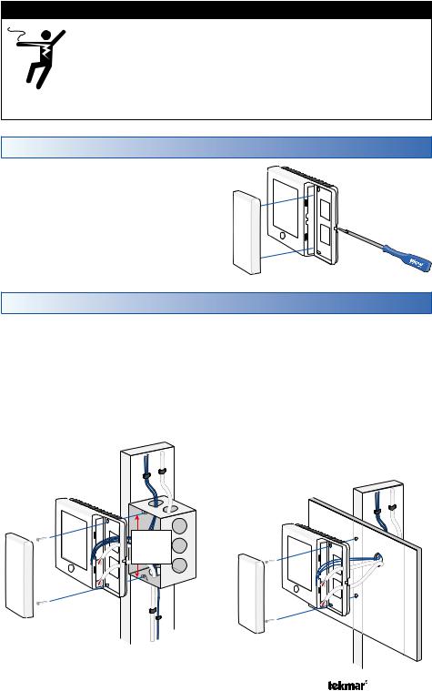
Removing The Wiring Cover
To remove the thermostat’s wiring cover:
• Locate the slotted hole on the right side of the thermostat.
• Insert a screwdriver in the slotted hole to depress the latch.
• Remove the wiring cover from the thermostat.
Mounting The Thermostat
If a single gang box is used:
•Feed the wiring through the large holes of the thermostat.
•Fasten the base of the thermostat to the gang box using two screws.
•Terminate wiring to the wiring strip.
•Re-install the wiring cover.
Stud
Thermostat
Switch Box
3 1/4”
(83 mm)
If a gang box is not used:
•Feed the wiring through the large holes in the thermostat.
•Use screws in the screw holes to fasten the thermostat to the wall. At least one of the screws should enter a wall stud or similar rigid material.
•Terminate wiring to the wiring strip.
•Re-install the wiring cover.
Stud
Thermostat
Wall
Wiring
Cover Wiring Cover
A Watts Water Technologies Company |
5 of 52 |
© 2014 |
557_D - 09/14 |

Thermostat Wiring
The thermostat operates a single heating system zone and can be wired in three different ways.
Stand Alone - Similar to tekmarNet®4 wiring with tN4 wiring terminal not used. First stage heating relay (Rh1 - W1) can be wired directly to switching relays.
tekmarNet®4 - Allows the thermostat to be wired using 4 wires to a tN4 Wiring Center or Zone Manager point-to-point. Alternatively, the thermostat can operate the heating and cooling equipment locally and the tN4 communication bus can be daisey-chained from one thermostat to another.
tekmarNet®2 - Allows the thermostat to be wired point-to-point using 2 wires to a tN2 Wiring Center, House Control, or Zone Manager. This allows easy wiring for retrofit applications.
Application specific wiring diagrams are provided in the 557_A brochure.
Compatible Sensors
The thermostat is compatible with Indoor Sensor type 076, 077, 084, Slab Sensor type 072, 073, 079, Outdoor Sensor type 070, Duct Sensor type 083 and Humidity & Temperature Sensor type 086.
Testing the Thermostat Wiring
Only qualified personnel should perform testing procedures. A licensed electrician is recommended.
Testing tekmarNet®2 Wiring ------------------------------------------
Testing the Power
If the thermostat display turns on, this indicates that the thermostat is operating correctly and there are no electrical issues. In the event that the display is off, or the display is cycling on and off:
1.Remove the thermostat wiring cover.
2.Check to ensure that the tN2 wires on the thermostat are connected to a zone on a House Control, Wiring Center, or Zone Manager.
3.Use an electrical meter to measure DC voltage between the tN2 terminals.
•If the DC voltage is 0 V (dc) for at least 20 seconds, then there is an open or short circuit in the tN2 wires.
•If the DC voltage is 0 V (dc) for 10 seconds and then is 23 to 24 V (dc) for 5 seconds, this indicates the wiring is correct.
A Watts Water Technologies Company |
6 of 52 |
© 2014 |
557_D - 09/14 |

4.If the thermostat display is off, or is cycling on and off, move the thermostat to the next available zone on the House Control, Wiring Center, or Zone Manager.
•If the thermostat display remains permanently on, there may be a fault with the previously tried zone on the House Control, Wiring Center, or Zone Manager.
•If the thermostat display continues to be off, or is cycling on and off, there may be a fault on the thermostat.
If a fault is suspected, contact your tekmar sales representative for assistance.
Testing tekmarNet®4 and Stand Alone Wiring --------------------------
Testing the Power
1.Remove the front cover from the thermostat.
2.Use an electrical test meter to measure (ac) voltage between the R and C terminals. The reading should be 24 V (ac) +/– 10%.
3.Install the front cover.
Testing the Relay Outputs --------------------------------------------
The thermostat includes a User Test to check if the thermostat’s relays are operating and that the thermostat is wired correctly to the HVAC equipment. The User Test setting can be located in the Toolbox menu. Either Heat or Cool test can be selected.
Cancel button - Exits the user test and returns the Toolbox menu. Hold button - Pauses the user test step for up to 5 minutes.
Next Item button - Advances the user test to the next test step.
User Test Sequence
|
Heat Test |
|
Cool Test |
|
Step |
Relay(s) Closed |
Step |
|
Relay(s) Closed |
O Relay OFF |
Rc-O/B is opened |
O Relay ON |
|
Rc-O/B |
|
|
|
|
|
B Relay ON |
Rc-O/B |
B Relay OFF |
|
Rc-O/B is opened |
|
|
|
|
|
Fan |
Rc-G |
Fan |
|
Rc-G |
|
|
|
|
|
Y1 Heat |
Rc-Y1 and Rc-G |
Y1 Cool |
|
Rc-Y1 and Rc-G |
|
|
|
|
|
Y2 Heat |
Rc-Y1 and Rc-Y2 and |
Y2 Cool |
|
Rc-Y1 and Rc-Y2 and |
|
Rc-G |
|
|
Rc-G |
W2 Heat |
Rh2-W2 |
W2 Cool |
|
Rh2-W2 |
|
|
|
|
|
W1 Heat |
Rh1-W1 |
Humidify* |
|
ACC-ACC |
|
|
|
|
|
Humidify* |
ACC-ACC |
Dehumidify* |
|
ACC-ACC or Rc-Y2 |
|
|
|
|
|
Dehumidify* |
ACC-ACC or Rc-Y2 |
HRV* |
|
Rc-Y2 |
|
|
|
|
|
HRV* |
Rc-Y2 |
Valve* |
|
ACC-ACC or Rc-Y2 |
|
|
|
|
|
Valve* |
ACC-ACC or Rc-Y2 |
|
|
|
|
|
|
|
|
*availability of test step and additional relay closures based upon Setup menu settings.
A Watts Water Technologies Company |
7 of 52 |
© 2014 |
557_D - 09/14 |
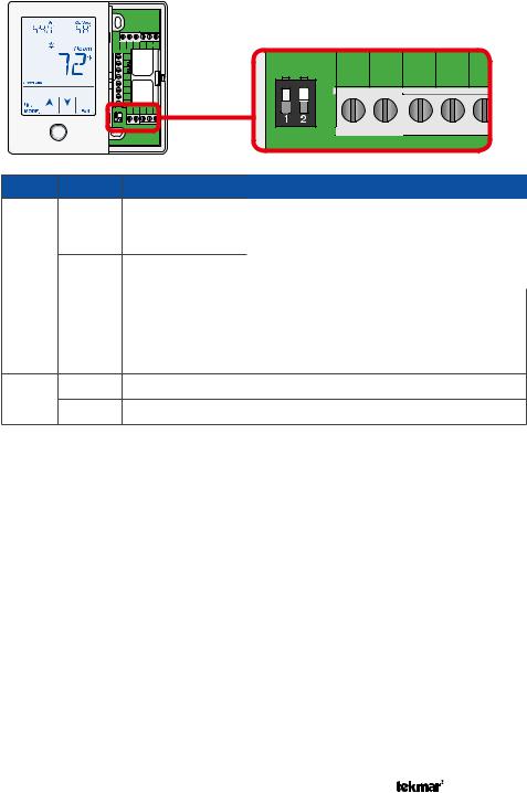
Switch Settings
Rh1 W1 Rh2 W2 |
ACC |
|
|
|
||
R |
|
|
|
|
|
|
C |
|
|
Y2 |
Y1 |
Rc |
G1 O/ |
S1 |
|
|
||||
tN4 |
|
|
|
|
|
|
S2 |
|
|
|
|
|
|
Com |
|
|
|
|
|
|
S3 |
|
|
|
|
|
|
0-10 Vdc |
|
|
|
|
|
|
Y2 |
Y1 |
Rc |
G1 O/B |
|
|
|
Switch Position Action
LOCK ACCESS LEVEL
ON Thermostat is locally locked and the access level cannot be changed. Set to Lock when installation has been completed.
UNLOCK ACCESS LEVEL
1 Thermostat is unlocked and the access level may be changed. Go to the Toolbox menu to change the access level. Set to Unlock during
OFF the installation process.
tekmarNet® system controls include a Global Lock that locks all connected thermostats. Set the tekmarNet® system control to unlock to allow access level adjustment on all connected thermostats.
ON Not used
2
OFF Not used
A Watts Water Technologies Company |
8 of 52 |
© 2014 |
557_D - 09/14 |
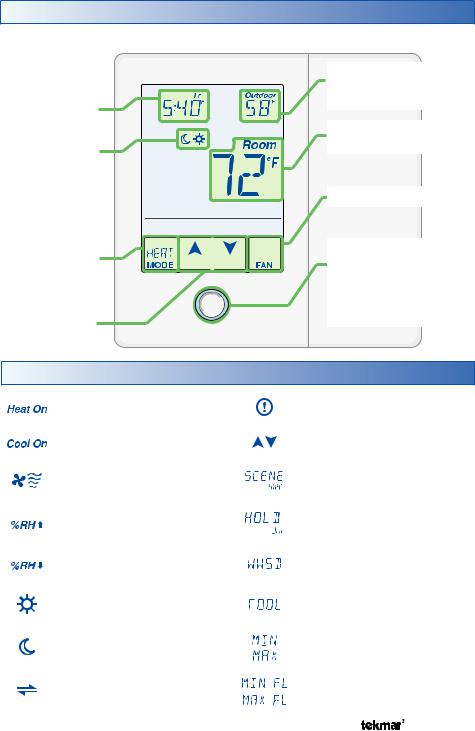
User Interface
Home Screen
The touchscreen of the 557 provides one touch access to these settings.
Adjust
the Time
Adjust the
Schedule
Away Key


Switch between
Auto, Heat,
Cool, Off &
Emergency Mode
Home
Adjust the Button
Temperature
Display Humidity, Heat & Cool settings, Floor or Outdoor temperature
Room
Temperature
Turn the Fan on
Home Button. Return to the ‘Home’
Screen from any menu. Press and hold for 3 seconds to access the programming menus.
Symbols Description
HEAT ON |
WARNING SYMBOL |
|
Heat is turned on. |
Indicates an error is present. |
|
COOL ON |
ARROWS |
|
Cooling is turned on. |
Adjust the displayed setting. |
|
FAN |
SCENE AWAY |
|
The fan is turned on. |
Operating at Away temperature. |
|
|
|
|
%RH |
TEMPORARY HOLD |
|
Holds temperature for 3, 6, 9 or |
||
Humidifying |
||
12 hours. |
||
|
||
%RH |
WWSD |
|
Dehumidifying |
Warm Weather Shut Down. |
|
|
|
|
SUN |
COOL |
|
Operating at the occupied (day) |
||
Cooling system is on. |
||
temperature. |
||
|
||
MOON |
MIN or MAX |
|
Operating at the unoccupied |
||
Reached the room min or max. |
||
(night) temperature. |
||
|
||
tekmarNet® |
MIN FL or MAX FL |
|
Communication is present. |
Reached the floor min or max. |
|
|
|
A Watts Water Technologies Company |
9 of 52 |
© 2014 |
557_D - 09/14 |

Programmable Settings
Programming Menus
Press and hold the Home button for 3 seconds to enter the programming menus. The thermostat returns to the last programming menu previously used.
Press and hold for 3 seconds to access the programming menus.
Select a Programming Menu -----------------------------------------
•Touch “NEXT” to advance (clockwise in above illustration) to the next menu.
•Touch “BACK” to go backwards (counterclockwise in above illustration) through the menus.
•Touch “ENTER” to enter a menu.
Setting Items --------------------------------------------------------
•Touch or
or arrow to adjust the setting if required.
•Touch “NEXT ITEM” to advance to the next item within the menu.
•Touch “BACK ITEM” to go backwards to the previous item within the menu.
•To return to the parent menu after changing a setting, press and release the Home button.
•To return to the Home screen, press and release the Home button twice or wait 30 seconds to automatically return to the Home screen.
A Watts Water Technologies Company |
10 of 52 |
© 2014 |
557_D - 09/14 |

Set Temp Menu (1 of 4)
Setting |
|
Display |
SET HEAT ROOM |
event. |
Room |
Set the room heating temperature for the |
|
|
Access Level: Installer, User |
|
Range: 40 to 95°F (4.5 to 35.0°C) |
Conditions: Always available |
|
Default: 70°F (21.0°C) |
SET HEAT ROOM |
event. |
Room |
Set the room heating temperature for the |
|
|
Access Level: Installer, User |
|
Range: 40 to 95°F (4.5 to 35.0°C) |
Conditions: Schedules are in use or Scenes are |
Default: 65°F (18.5°C) |
|
set to All or Guest. |
|
|
|
|
|
SET HEAT ROOM AWAY |
|
Room |
Set the room heating temperature for the Away |
||
scene. |
|
|
Access Level: Installer, User |
|
Range: 40 to 95°F (4.5 to 35.0°C) |
Conditions: Scenes is set to Away, All or Guest. |
Default: 62°F (16.5°C) |
|
HEAT MINIMUM ROOM LIMIT |
|
|
Set the minimum room heating limit. |
|
|
Access Level: Installer |
|
Range: 40 to 95°F (4.5 to 35.0°C) |
Conditions: Schedules are in use or Scenes are |
Default: 40°F (4.5°C) |
|
set to All or Guest. |
|
|
|
|
|
HEAT MAXIMUM ROOM LIMIT |
|
|
Set the maximum room heating limit for the |
|
|
event. |
|
|
Access Level: Installer |
|
Range: 40 to 95°F (4.5 to 35.0°C) |
Conditions: Always available |
|
Default: 85°F (29.5°C) |
HEAT MAXIMUM ROOM LIMIT |
|
|
Set the maximum room heating limit for the |
|
|
event. |
|
|
Access Level: Installer |
|
Range: 40 to 95°F (4.5 to 35.0°C) |
Conditions: Schedules are in use or Scenes are |
Default: 85°F (29.5°C) |
|
set to All or Guest. |
|
|
|
|
|
WARM WEATHER SHUT DOWN |
|
|
Set the outdoor air temperature at which heating is |
|
|
suspended during the event. |
|
|
Access Level: Installer |
|
Range: CTRL (control), 40 to |
|
100°F (4.5 to 38.0°C), OFF |
|
|
|
|
Conditions: An outdoor sensor must be available. Default: CTRL
A Watts Water Technologies Company |
11 of 52 |
© 2014 |
557_D - 09/14 |
Set Temp Menu (2 of 4)
Setting |
|
Display |
WARM WEATHER SHUT DOWN |
|
|
Set the outdoor air temperature at which heating is |
|
|
suspended during the event. |
|
|
Access Level: Installer |
|
Range: CTRL (control), 40 to |
|
100°F (4.5 to 38.0°C), OFF |
|
|
|
|
Conditions: An outdoor sensor must be available |
|
|
and Schedules are in use or Scenes is set to All or |
Default: CTRL |
|
Guest. |
|
|
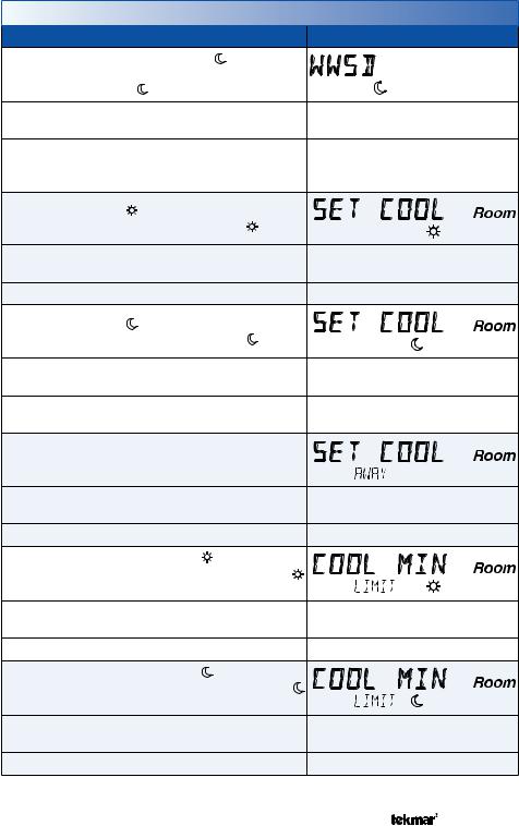
SET COOL ROOM |
|
|
Set the room cooling temperature for the |
event. |
|
Access Level: Installer, User |
|
Range: 50 to 100°F (10.0 to |
|
38.0°C) |
|
|
|
|
Conditions: Always |
|
Default: 78°F (25.5°C) |
SET COOL ROOM |
|
|
Set the room cooling temperature for the |
event. |
|
Access Level: Installer, User |
|
Range: 50 to 100°F (10.0 to |
|
38.0°C) |
|
|
|
|
Conditions: Requires that Schedules are in use or |
Default: 85°F (29.5°C) |
|
Scenes is set to All or Guest. |
|
|
|
|
|
SET COOL ROOM AWAY |
|
|
Set the room cooling temperature during the Away |
|
|
scene. |
|
|
Access Level: Installer |
|
Range: 50 to 100°F (10.0 to |
|
38.0°C) |
|
|
|
|
Conditions: Scenes is set to Away, All or Guest. |
Default: 85°F (29.5°C) |
|
COOL MINIMUM ROOM LIMIT |
|
|
Set the minimum room cooling limit while in the |
|
|
event. |
|
|
Access Level: Installer |
|
Range: 50 to 100°F (10.0 to |
|
38.0°C) |
|
|
|
|
Conditions: Always available. |
|
Default: 50°F (10.0°C) |
COOL MINIMUM ROOM LIMIT |
|
|
Set the minimum room cooling limit while in the |
|
|
event. |
|
|
Access Level: Installer |
|
Range: 50 to 100°F (10.0 to |
|
38.0°C) |
|
|
|
|
Conditions: Always available. |
|
Default: 50°F (10.0°C) |
A Watts Water Technologies Company |
12 of 52 |
© 2014 |
557_D - 09/14 |
Set Temp Menu (3 of 4)
Setting |
Display |
|
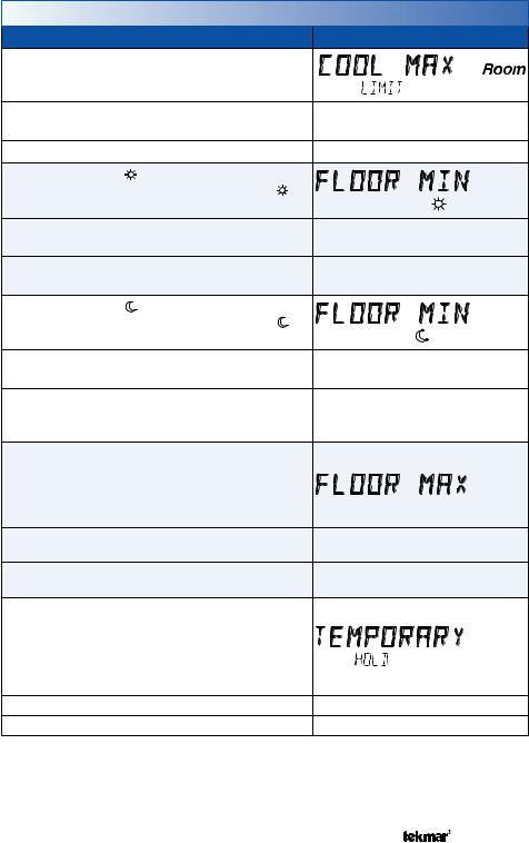
COOL MAXIMUM ROOM LIMIT |
|
|
Set the maximum room cooling limit. |
|
|
Access Level: Installer |
Range: 50 to 100°F (10.0 to |
|
38.0°C) |
||
|
||
Conditions: Always available |
Default: 100°F (38.0°C) |
|
FLOOR MINIMUM |
|
|
Set the floor heating temperature while in the |
|
|
event. |
|
|
Access Level: Installer, User |
Range: OFF, 40 to 122°F (4.5 to |
|
50.0°C) |
||
|
||
Conditions: Sensor 1, 2 or 3 is set to Floor, and W1 |
Default: 72°F (22.0°C) |
|
Terminal is set to HRF1, HRF2 or Othr. |
|
|
FLOOR MINIMUM |
|
|
Set the floor heating temperature while in the |
|
|
event. |
|
|
Access Level: Installer, User |
Range: OFF, 40 to 122°F (4.5 to |
|
50.0°C) |
||
|
||
Conditions: Sensor 1, 2 or 3 is set to Floor, and W1 |
|
|
Terminal is set to HRF1, HRF2 or Othr, & Schedules Default: OFF |
||
are in use or Scenes are set to All or Guest. |
|
|
FLOOR MAXIMUM |
|
|
Set the floor maximum temperature in order to |
|
|
protect the floor covering. |
|
|
Suggested settings: Tile = 90°F (32°C) |
|
|
Hardwood Floor = 85°F (29°C) |
|
|
Access Level: Installer |
Range: 40 to 122°F (4.5 to |
|
50.0°C), OFF |
||
|
||
Conditions: Sensor 1, 2 or 3 is set to Floor, & W1 |
Default: 85°F (29.5°C) |
|
Terminal is set to HRF1, HRF2 or Othr. |
||
|
||
TEMPORARY HOLD |
|
|
Temperature adjustment in the home menu |
|
|
can result in either permanent temperature |
|
|
setting change or temporary temperature setting |
|
|
change that lasts 3, 6, 9, 12 hours or until the |
|
|
next scheduled event. |
|
|
Access Level: Installer |
Range: OFF or ON |
|
Conditions: None |
Default: OFF |
|
A Watts Water Technologies Company |
13 of 52 |
© 2014 |
557_D - 09/14 |
Set Temp Menu (4 of 4)
Setting |
|
Display |
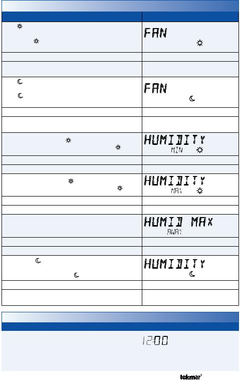
FAN |
|
|
Set the minimum percentage the fan should operate |
|
|
while in the event. This provides ventilation for the |
|
|
building. Each 10% is 6 minutes per hour. |
|
|
Access Level: Installer, User |
|
Range: Auto, 10 to 90%, ON |
Conditions: Always available. 10 to 90% available |
Default: Auto |
|
when Ventilation Mode is On. |
|
|
|
|
|
FAN |
|
|
Set the minimum percentage the fan should operate while |
|
|
in the event or Away scene. This provides ventilation |
|
|
for the building. Each 10% is 6 minutes per hour. |
|
|
Access Level: Installer, User |
|
Range: Auto, 10 to 90%, ON |
Conditions: Schedules used or Scenes set to Guest or |
Default: Auto |
|
All. 10 to 90% available when Ventilation Mode is On. |
||
HUMIDITY MINIMUM |
|
|
Set the minimum humidity level during the |
event. |
|
Access Level: Installer, User |
|
Range: OFF, 20 to 80% |
Conditions: Humidify Mode set to HM1, 2, 3. |
|
Default: 40% |
HUMIDITY MAXIMUM |
|
|
Set the maximum humidity level during the |
event. |
|
Access Level: Installer, User |
|
Range: 20 to 80%, OFF |
Conditions: Dehumidify Mode set to DHM1, 2, 3, 4, 5. |
Default: 60% |
|
HUMIDITY MAXIMUM AWAY |
|
|
Set the maximum humidity level during Away scene. |
|
|
Access Level: Installer |
|
Range: 20 to 80%, OFF |
Conditions: Dehumidify Mode set to DHM1, 2, 3, 4, 5. |
Default: OFF |
|
HUMIDITY |
|
|
Select if the humidification or dehumidification system |
|
|
should operate during the event or away scene. |
|
|
Access Level: Installer |
|
Range: OFF or On |
Conditions: Humidity Mode set to DHM1, 2, 3 or |
Default: OFF |
|
Dehumidity Mode set to DHM1, 2, 3, 4, 5. |
|
|
|
|
|
Time Menu (1 of 2)
|
|
Setting |
Display |
MINUTES |
|
Select the current time minutes. |
|
|
|
Access Level: Installer, User |
Range: 00 to 59 |
Conditions: Always available. |
Default: 00 |
A Watts Water Technologies Company |
14 of 52 |
© 2014 |
557_D - 09/14 |

Time Menu (2 of 2)
Setting |
Display |
HOURS |
|
Select the current time hours. |
|
Access Level: Installer, User |
Range: 12 AM to 11 PM or 00 to 23 |
Conditions: Always available. |
Default: 12 AM |
DAY OF WEEK |
|
Select the current day of the week. |
|
Access Level: Installer, User |
Range: Sunday to Saturday |
Conditions: Always available. |
Default: Sunday |
MONTH |
|
Select the current month. |
|
Access Level: Installer, User |
Range: JANUARY to DECEMBER |
Conditions: Always available. |
Default: JANUARY |
DAY OF MONTH |
|
Select the day of the current month. |
|
Access Level: Installer, User |
Range: 1 to 31 |
Conditions: Always available. |
Default: 1 |
YEAR |
|
Select the current year. |
|
Access Level: Installer, User |
Range: 2012 to 2255 |
Conditions: Always available. |
Default: 2012 |
DAYLIGHT SAVINGS TIME |
|
Select if daylight savings time is observed. |
|
Access Level: Installer, User |
Range: OFF or ON |
Conditions: Always available. |
Default: ON |
TIME MODE |
|
Select either 12 or 24 hour time format. |
|
Access Level: Installer, User |
Range: 12 or 24 hour |
Conditions: Always available. |
Default: 12 hour |
CLOCK |
|
Select whether to show the time clock on the display. |
|
Access Level: Installer, User |
Range: OFF or ON |
Conditions: The time is always shown when a |
|
schedule is used and the clock setting option is no |
Default: OFF |
longer available. |
|
A Watts Water Technologies Company |
15 of 52 |
© 2014 |
557_D - 09/14 |

Schedule Menu (1 of 2)
The schedule menu can operate on a 24 hour or 7 day repeating schedule. When a 24 hour schedule is selected, “SuMoTuWeThFrSa” is shown on the top of the screen to show that the event time applies to all days of the week. When a 7 day schedule is selected, each individual day of the week is shown with the event time.
Setting |
|
Display |
|
EVENT 1 |
|
SuMoTuWeThFrSa |
|
The first programmable schedule time period of |
|
||
the day. The |
temperature settings are used |
|
|
during this time period. |
|
||
Access Level: Installer, User |
Range: 12:00 AM to 11:50 PM, SKIP |
||
or 00:00 to 23:50, SKIP |
|||
|
|
||
Conditions: Schedule setting is set to Zone or |
Default: 6:00 AM |
||
Master 1, 2, 3, 4 and Event/Day is set to 2 or 4. |
|||
|
|||
EVENT 2 |
|
SuMoTuWeThFrSa |
|
The second programmable schedule time period |
|
||
of the day. The |
temperature settings are used |
|
|
during this time period. |
|
||
Access Level: Installer, User |
Range: 12:00 AM to 11:50 PM, SKIP |
||
or 00:00 to 23:50, SKIP |
|||
|
|
||
Default:
Conditions: Schedule setting is set to Zone or 10:00 PM when Event/Day is 2 Master 1, 2, 3, 4 and Event/Day is set to 2 or 4.
8:00 AM when Event/Day is 4
EVENT 3 |
|
SuMoTuWeThFrSa |
|
The third programmable schedule time period |
|
||
of the day. The |
temperature settings are used |
|
|
during this time period. |
|
||
Access Level: Installer, User |
Range: 12:00 AM to 11:50 PM, SKIP |
||
or 00:00 to 23:50, SKIP |
|||
|
|
||
Conditions: Schedule setting is set to Zone or |
Default: 6:00 PM |
||
Master 1, 2, 3, 4 and Event/Day is set to 4. |
|||
|
|||
EVENT 4 |
|
SuMoTuWeThFrSa |
|
The fourth programmable schedule time period |
|
||
of the day. The |
temperature settings are used |
|
|
during this time period. |
|
||
Access Level: Installer, User |
Range: 12:00 AM to 11:50 PM, SKIP |
||
or 00:00 to 23:50, SKIP |
|||
|
|
||
Conditions: Schedule setting is set to Zone or |
Default: 10:00 PM |
||
Master 1, 2, 3, 4 and Event/Day is set to 4. |
|||
|
|||
A Watts Water Technologies Company |
16 of 52 |
© 2014 |
557_D - 09/14 |
 Loading...