


|
|
|
|
- Data Brochure |
|
|
|
|
|
|
|
D422 |
|||||||
Universal Reset Module 422 |
|
|
|
|
|
|
|
|
|
|
|
08/07 |
|||||||
|
|
|
|
|
|
|
|
|
|
|
|
|
|
|
|
|
|
|
|
|
|
|
|
|
|
|
|
|
|
|
|
|
|
|
|
|
|
|
|
1 |
Information |
|
2 |
Application |
3 |
|
Rough-in |
|
4 |
Wiring |
5 |
|
Data |
|
6 |
|
Job |
||
|
|
|
|||||||||||||||||
|
Brochure |
|
|
Brochure |
|
|
|
Wiring |
|
|
Brochure |
|
|
|
Brochure |
|
|
|
Record |
Choose controls |
|
|
Design your |
|
|
|
Rough-in |
|
|
Wiring and |
|
|
Control settings |
|
Record settings & |
||||
|
to match |
|
|
mechanical |
|
|
|
wiring |
|
|
installation of |
|
and sequence of |
|
|
wiring details for |
|||
|
application |
|
|
applications |
|
|
|
instructions |
|
|
specific control |
|
|
|
operation |
|
|
future reference |
|
|
|
|
|
|
|
|
|
|
|
|
|
|
|
|
|
|
|
|
|
Introduction
The Universal Reset Module 422 provides outdoor reset to a hydronic heating system in order to maximize comfort and efficiency. The 422 can operate a single on / off boiler or a single modulating boiler. The 422 can override the outdoor reset water temperature to provide Domestic Hot Water or Setpoint operations. The 422 can operate two outdoor reset water temperatures, either one boiler water temperature and a single mix water temperature, or two mix water temperatures. To operate two mixing devices, a Mixing Expansion Module must be connected to the 422. The single mix output can operate a floating action mixing valve or a variable speed injection pump.
Features:
• |
tN4 Compatible |
• |
DHW Operation |
• Two Outdoor Reset Temperatures |
• Variable Speed Injection Pump |
||
• Single On-Off or Modulating Boiler |
• |
Floating Action Valve |
|
• |
Powered Pump Outputs |
• |
Includes Sensors |
Boiler |
DHW |
Setpoint |
Demand Demand
51 52 53 54 55 56
H7008B
/ |
tN4 Boiler / Mix 2 |
Boil Sens Sup / Ret |
Boiler On-O / Mod |
O / tekmar Stager |
O / Flushing |
Meets Class B: Canadian
ICES & FCC Part 15
Made in Canada
C |
R |
C2 |
tN4 |
C |
Opn |
Cls |
+ |
– |
Com Boil |
Mix |
Com Out |
24 V (ac) |
Boil/Mix2 |
Floating Output: |
R |
|
R |
Mod (dc) |
|
|
||||||
57 |
|
58 |
59 |
|
60 |
24 V (ac) 8 VA |
61 62 |
|
63 |
64 |
|
65 |
66 |
67 68 69 70 |
|
|
|
|
|||||||||||
Output 1 VA |
|
|
|
|
Powered Output |
|
|
Do not apply power |
||||||
|
|
|
|
|
|
Universal Reset Module 422 |
|
tN4 |
||||||
Menu
Item
tektra 991-03
Var. Pump: 115 V (ac) 2.5 A
Demands: 20 - 260 V (ac)
Relay Rating: 115 V (ac) 5 A
Test |
|
|
|
|
|
|
|
2.5 A |
|
|
|
|
|
|
|
10 A |
|
|
71 |
|
72 |
73 |
74 |
|
75 |
76 |
77 |
78 |
max. |
||||||
|
|
|
|
DHW |
|
Variable Speed |
|
|
|
Primary |
|
Mix Sys P1 |
|
||||
|
Pump |
|
N |
Pump |
N |
|
Pump |
N |
Pump |
N |
|
||||||
Var. Pump Fuse
T2.5 A 250 V
1 of 32 |
© 2007 |
D 422 - 08/07 |

Table of Contents
Table of Contents ........................................................... |
2 |
Display and DIP Switches .............................................. |
2 |
Dip Switch Settings ................................................ |
2 |
Access Level ........................................................... |
3 |
Display and Symbols Description............................ |
4 |
User Interface ........................................................ |
5 |
Display Menus ................................................................ |
6 |
View Menu .............................................................. |
6 |
Adjust Menu ............................................................ |
8 |
Miscellaneous Menu ............................................. |
13 |
Testing the Control ....................................................... |
14 |
Sequence of Operation................................................. |
16 |
tekmarNet®4 Communication ............................... |
16 |
Outdoor Reset ...................................................... |
16 |
Boiler Temperature Control .................................. |
19 |
tekmar Stager Operation ...................................... |
21 |
Boil Enable............................................................ |
22 |
Direct Fired - DHW Tank as a Heat Source ......... |
22 |
Zone Load Shedding ............................................ |
22 |
Mixing Operation .................................................. |
22 |
Domestic Hot Water Temperature Operation ....... |
23 |
DHW with Low Temperature Boilers ..................... |
25 |
Setpoint Temperature Operation ........................... |
25 |
Pump Operation.................................................... |
27 |
Pump Exercising ................................................... |
27 |
Error Messages ............................................................ |
28 |
Troubleshooting ............................................................ |
31 |
Warranty ....................................................................... |
32 |
Display and DIP Switches
Dip Switch Settings
Set the DIP switch settings prior to making adjustments to the control through the user interface. Setting the DIP switches determines which menu items are displayed in the user interface.
If you change a DIP switch setting while the control is powered up, the LCD display returns to the View menu.
Lock / Unlock
Use the Lock / Unlock DIP switch to lock and unlock the Access Level of the 422 and all connected tN4 devices, including tN4 thermostats. For details, see “Access Levels”
•Once locked, the access level in all devices cannot be viewed or changed.
•To determine if the control is currently locked a small segment representing a padlock is viewed in the bottom right hand corner of the display.
•To unlock the Access Level, set the DIP switch to Unlock.
•To lock the Access Level, set the DIP switch to Lock.
/ |
|
|
|
|
|
tN4 Boiler / Mix 2 |
|
|
|
|
|
Boil Sens Sup / Ret |
|
|
|
|
|
Boiler On-O / Mod |
|
|
|
|
|
O / tekmar Stager |
Setpoint |
C |
R |
C2 |
tN4 |
O / Flushing |
56 |
57 |
58 |
59 |
60 |
|
Demand |
24 V (ac) |
Boil/Mix2 |
||
|
|
Output 1 VA |
|
|
|
H7008B |
|
Menu |
|
|
|
|
Item |
|
|
||
tN4 Boiler / Mix 2 |
|
|
|||
/ |
|
|
|
|
|
Boil Sens Sup / Ret |
|
|
|
|
|
Boiler On-O / Mod |
|
|
|
|
|
O / tekmar Stager |
|
|
|
|
|
O / Flushing |
|
|
|
|
|
Meets Class B: Canadian |
|
|
|
|
|
ICES & FCC Part 15 |
|
|
|
|
|
Made in Canada |
|
|
|
|
|
Test |
71 |
72 |
73 |
74 |
2.5 A |
|
|
||||
|
DHW |
|
Variable Speed |
||
|
Pump |
N |
Pump |
N |
|
Var. Pump Fuse
T2.5 A 250 V
|
|
|
|
|
|
|
|
|
|
|
|
|
C |
Opn |
Cls |
+ |
– |
Com Boil |
Mix Com |
Out |
|||
Floating Output: |
R |
|
R |
Mod (dc) |
|
|
|
|
|
||
24 V (ac) 8 VA 61 |
62 |
63 |
64 |
65 |
66 67 68 69 70 |
||||||
Powered Output |
Do not apply power |
|
|||||||||
Universal Reset Module 422 |
|
|
tN4 |
|
|||||||
|
|
|
|
|
|
tektra 991-03 |
|
|
|
||
|
|
|
|
|
|
Var. Pump: 115 V (ac) 2.5 A |
|
||||
|
|
|
|
|
|
Demands: 20 - 260 V (ac) |
|
||||
|
|
|
|
|
|
Relay Rating: 115 V (ac) 5 A |
|
||||
|
|
|
|
|
|
|
|
|
|
|
10 A |
|
|
|
|
|
75 |
76 |
77 |
78 |
|
max. |
|
|
|
|
|
|
Primary |
|
Mix Sys P1 |
|
|||
|
|
|
|
Pump |
N |
|
Pump |
N |
|
||
|
|
|
|
|
|
|
|
|
|
|
|
© 2007 |
D 422 - 08/07 |
2 of 32 |

tN4 Boiler / Mix 2
Use the tN4 Boiler / Mix 2 DIP switch to select whether the second tN4 bus (terminals 59-60) is to operate as a boiler water temperature or as a second mixing water temperature.
•If set to Boiler, this creates a system with one boiler and one mix water temperature.
•If set to Mix 2, this creates a system with two mix water temperatures. If Mix 2 is selected, a mixing expansion module must be connected to the Boiler / Mix 2 bus.
Boiler Sup / Ret
Use the Boiler Sensor Supply / Return DIP switch to select the location of the boiler sensor.
•If the boiler sensor is located on the supply, this DIP switch should be set to Sup. The 422 is the control that determines the boiler water temperature. Set the boiler’s aquastat at least 20°F (11.0°C) higher than the Boiler Maximum setting.
•If the 422 provides a heat demand to an external boiler control, this DIP switch must be set to Ret. Install the boiler sensor on the return side of the boiler loop. The boiler’s operating temperature is controlled by its aquastat, or an external boiler reset control.
Boil On-Off / Mod
The Boil On-Off / Mod DIP switch selects whether the control operates an On-Off boiler or the firing rate of a Modulating boiler.
•If set to Boil On-Off, the control operates an On-Off boiler.
•If set to Mod, the control operates a Modulating boiler.
Off / Flushing
The Off / Flushing DIP switch selects whether the control operates a Flushing feature. Heating systems that use potable water require periodic flushing to prevent the water from stagnating.
The flushing operation occurs if any zone has not operated for 7 days. All zones, mixing device(s), and applicable system pumps are turned on for 4 minutes.
•To activate the Flushing feature, set to Flushing.
•To deactivate the Flushing feature, set to Off.
tekmar Stager / Off
Use the tekmar Stager / Off DIP switch when a tekmar staging control is be connected to the 422 in order to operate multiple boilers. A tekmar stager may include Boiler Controls 264, 265, and 268.
•If a tekmar Stager is installed, set to tekmar Stager. The 422 will then provide the stager with a target temperature via a 0-10 V (dc) signal. When the tekmar Stager / Off DIP switch is set to tekmar Stager, the Boiler Sensor DIP switch must be set to Sup.
•If a tekmar Stager is not installed, set to Off.
Access Level
The Access Level restricts the number of Menus, Items, and Adjustments that can be accessed by the user. The Access Level setting is found in the Miscellaneous (MISC) menu. Select the appropriate access level for the people who work with the control on a regular basis.
There are two Access Level settings:
•Installer (InS): This is the factory default setting. This access level is sufficient for the normal set up of the control.
•Advanced (Ad): All of the control settings are available to the user.
In the following menu tables, the access level the item is visible in is shown in the access column.
3 of 32 |
© 2007 |
D 422 - 08/07 |

SymbolsDisplay Description |
S |
Menu Field
Displays the current menu
Status Field
Displays the current status of the control’s inputs, outputs and operation. Most symbols in the status field are only visible when the VIEW Menu is selected
Item Field
Displays an |
abbreviated name |
of the selected item |
Number Field |
Displays the |
current value of |
the selected item |
Symbols Description
PUMP
Displays when the primary or mixing pump is in operation.
BURNER
Displays when the burner contact is closed.
LOCK
Displays when the access levels are locked.
WARNING
Displays when an error exists.
COMMUNICATION BUS
Displays when tN4 thermostats are connected.
DHW PUMP
Displays when the DHW Pump is in operation.
°F, °C, %, HOURS, MINUTES
Units of measurement.
BOILER DEMAND
Displays when a boiler demand is present.
MIX 1 DEMAND
Displays when a mix 1 demand is present.
MIX 2 DEMAND
Displays when a mix 2 demand is present.
DHW DEMAND
Displays when a DHW demand is present.
SETPOINT DEMAND
Displays when a Setpoint demand is present.
DEVICE OUTPUT SCALE
Displays output of the modulating boiler, injection pump, or mixing valve.
OPEN / CLOSE
Displays whether the actuator is opening or closing the mixing valve.
© 2007 |
D 422 - 08/07 |
4 of 32 |

User Interface
Use the User Interface available on the Liquid Crystal Display (LCD) to setup and monitor the operation of the system. Use the four push buttons to the left of the LCD (Menu, Item, Up, Down) to select settings. As you enter settings, record the settings in the Job Record J 422.
Menu
The menus display in the Menu Field at the top left side of the LCD. Three menus are available: View, Adjust, and Miscellaneous.
• To select a menu, press and release the Menu button.
Item
In each menu, a group of items can be selected. The abbreviated name of the selected item displays in the Item field of the LCD display.
•To view the next available item, press and release the Item button.
•To view the previous item, hold down the Item button. and press and release the Up button.

 Back to View Menu
Adjusting a Setting
To adjust a setting:
1.Select the appropriate menu using the Menu button.
2.Select the item using the Item button.
3.Use the Up or Down button to make the adjustment.
Default Item
•To set the default item in the View menu, display the item for more than five seconds.
After navigating menus, the display reverts back to the default item after 60 seconds of button inactivity.
Continue to next Item
Continue to next Item
Continue to next Item
5 of 32 |
© 2007 |
D 422 - 08/07 |
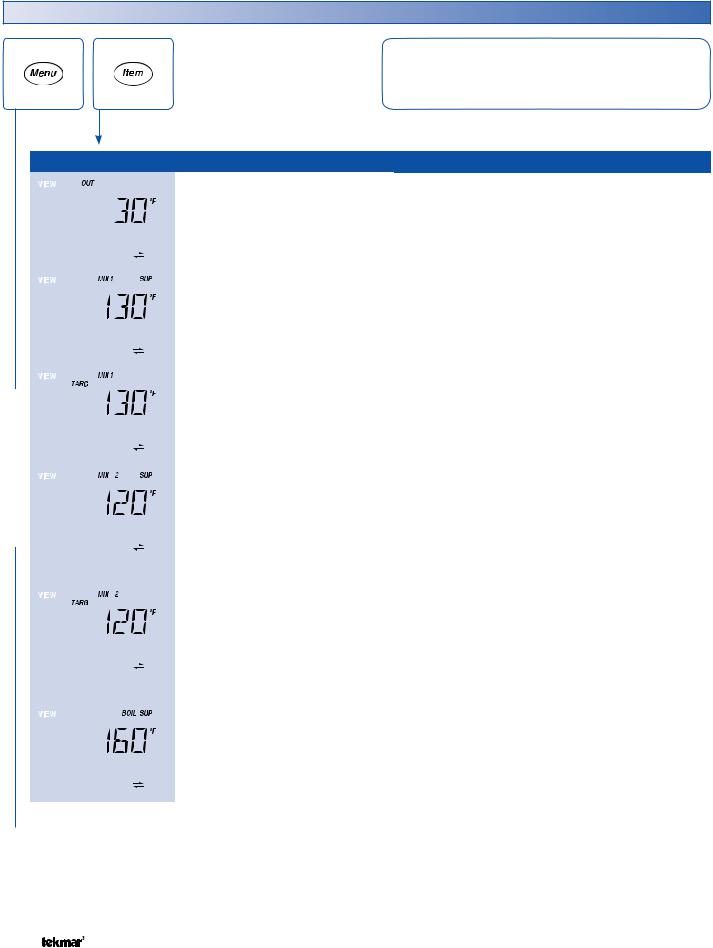
Display Menus
View Menu (1 of 2)
The View menu items display the current operating temperatures and status information of the system.
VIEW MENU
|
|
|
Item Field |
Range |
Access |
|
Description |
|
|
|
|
|
|
-76 to 149°F |
InS |
OUTDOOR |
SECTION B |
|
|
|
|
|
||||
|
|
|
|
|
||||
|
|
|
|
|
Current outdoor air temperature as measured by the |
|||
|
|
|
|
|
(-60.0 to 65.0°C) |
Ad |
||
|
|
|
|
|
outdoor sensor. |
|
||
|
|
|
|
|
|
|
|
|
|
|
|
|
|
|
|
|
|
|
|
|
|
|
|
|
|
|
|
|
|
|
|
-22 to 266°F |
InS |
MIX 1 SUPPLY |
SECTION B |
|
|
|
|
|
||||
|
|
|
|
|
||||
|
|
|
|
|
Current Mix 1 supply water temperature as measured |
|||
|
|
|
|
|
(-30.0 to 130.0°C) |
Ad |
||
|
|
|
|
|
by the Mix 1 supply sensor. |
|||
|
|
|
|
|
|
|
||
|
|
|
|
|
|
|
|
|
|
|
|
|
|
|
|
|
|
|
|
|
|
|
|
|
MIX 1 TARGET |
SECTION C |
|
|
|
|
|
|
|
||
|
|
|
|
|
|
|
||
|
|
|
|
|
– – –, 35 to 230°F |
Ad |
The Mix 1 target is the temperature the control |
|
|
|
|
|
|
is currently trying to maintain at the Mix 1 supply |
|||
|
|
|
|
|
(– – –, 1.5 to 110.0°C) |
|||
|
|
|
|
|
|
sensor. “– – –” is displayed when no heat is required |
||
|
|
|
|
|
|
|
||
|
|
|
|
|
|
|
for Mix 1 zones. |
|
|
|
|
|
|
|
|
|
|
|
|
|
|
|
|
|
MIX 2 SUPPLY |
SECTION B |
|
|
|
|
|
|
|
||
|
|
|
|
|
|
|
||
|
|
|
|
|
-22 to 266°F |
InS |
Current Mix 2 supply water temperature as measured |
|
|
|
|
|
|
by the Mix 2 supply sensor. |
|||
|
|
|
|
|
(-30.0 to 130.0°C) |
Ad |
||
|
|
|
|
|
Note: This item is only available when the tN4 DIP |
|||
|
|
|
|
|
|
|
||
|
|
|
|
|
|
|
switch is set to Mix 2. |
|
|
|
|
|
|
|
|
|
|
|
|
|
|
|
|
|
MIX 2 TARGET |
SECTION C |
|
|
|
|
|
|
|
The mix 2 target is the temperature the control |
|
|
|
|
|
|
|
|
||
|
|
|
|
|
– – –, 35 to 230°F |
|
is currently trying to maintain at the Mix 2 supply |
|
|
|
|
|
|
Ad |
sensor. “– – –” is displayed when no heat is required |
||
|
|
|
|
|
(– – –, 1.5 to 110.0°C) |
|||
|
|
|
|
|
|
for mix 2 zones. |
|
|
|
|
|
|
|
|
|
|
|
|
|
|
|
|
|
|
Note: This item is only available when the tN4 DIP |
|
|
|
|
|
|
|
|
switch is set to Mix 2. |
|
|
|
|
|
|
|
|
|
|
|
|
|
|
|
|
|
BOILER SUPPLY |
SECTION C |
|
|
|
|
|
|
|
||
|
|
|
|
|
|
|
||
|
|
|
|
|
-22 to 266°F |
InS |
Current boiler supply water temperature as measured |
|
|
|
|
|
|
by the boiler sensor. |
|||
|
|
|
|
|
(-30.0 to 130.0°C) |
Ad |
||
|
|
|
|
|
Note: This item is only available when the Boiler |
|||
|
|
|
|
|
|
|
||
|
|
|
|
|
|
|
Sensor Sup / Ret DIP switch is set to Sup. |
|
|
|
|
|
|
|
|
|
|
 Continued on next page.
© 2007 |
D 422 - 08/07 |
6 of 32 |
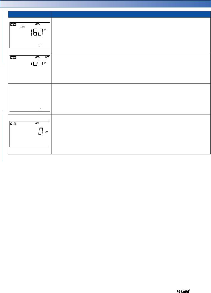
View Menu (2 of 2)
Item Field
MENUVIEW
Range |
Access |
Description |
|
|
|
|
BOILER TARGET |
SECTION C |
|
|
|
The boiler target is the temperature the control is currently |
||
– – –, 35 to 230°F |
Ad |
trying to maintain at the boiler supply sensor. “– – –” is |
||
(– – –, 1.5 to 110.0°C) |
displayed when no heat is required for boiler zones. |
|||
|
||||
|
|
Note: This item is only available when the Boiler |
||
|
|
Sensor Sup / Ret DIP switch is set to Sup. |
||
|
|
BOILER RETURN |
SECTION G |
|
-22 to 266°F |
InS |
Current boiler return water temperature as measured |
||
by the boiler sensor. |
|
|||
(-30.0 to 130.0°C) |
Ad |
|
||
Note: This item is only available when the Boiler |
||||
|
|
|||
|
|
Sensor Sup / Ret DIP switch is set to Ret. |
||
|
|
BOILER MODULATION |
SECTION C |
|
|
|
Current percent modulation of the boiler’s burner. |
||
0-100% |
Ad |
Note: This item is only available when the Boiler |
||
|
|
|||
|
|
On-Off / Mod DIP switch is set to Mod, and the Boiler |
||
|
|
Sensor Sup / Ret DIP switch is set to Sup. |
||
|
|
BOILER |
|
|
|
|
The total running time of the boiler since this item |
||
|
InS |
was last cleared. To clear this item, press the Up |
||
0 to 9999 hr |
and Down buttons simultaneously while viewing |
|||
Ad |
||||
|
this item. |
|
||
|
|
|
||
|
|
Note: This item is only available when the Boiler |
||
|
|
Sensor Sup / Ret DIP switch is set to Sup. |
||
|
|
|
|
|
 After the last item, the control returns to the first item in the menu.
7 of 32 |
© 2007 |
D 422 - 08/07 |
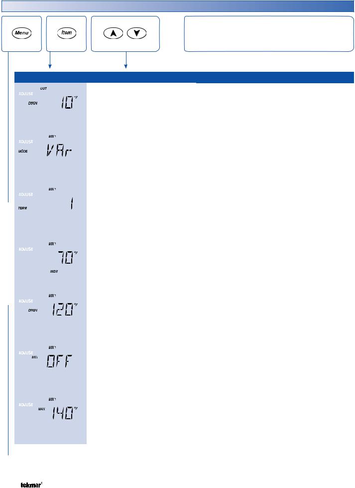
Adjust Menu (1 of 5)
ADJUST MENU
The Adjust Menu items are the programmable settings used to operate the mechanical equipment.
|
|
|
Item Field |
Range |
Access |
Description |
|
|
|
|
|
|
|
-60 to 45°F |
|
OUTDOOR DESIGN |
SECTION B |
|
|
|
|
|
|
|||
|
|
|
|
|
|
|||
|
|
|
|
|
|
|||
|
|
|
|
|
(-51.0 to 7.0°C) |
InS |
The design outdoor air temperature used in the heat |
|
|
|
|
|
|
Default = 10°F |
Ad |
loss calculations for the heating system. Typically set |
|
|
|
|
|
|
(-12.0°C) |
|
to the temperature of the coldest day of the year. |
|
|
|
|
|
|
|
|
|
|
|
|
|
|
|
|
|
|
|
|
|
|
|
|
VAr, FLt |
InS |
MIX 1 MODE |
SECTION G |
|
|
|
|
|
||||
|
|
|
|
|
||||
|
|
|
|
|
||||
|
|
|
|
|
Select the type of mixing device to be used for Mix 1. |
|||
|
|
|
|
|
Default = VAr |
Ad |
Options are variable speed injection pump (VAr) or |
|
|
|
|
|
|
|
|
floating action (FLt). |
|
|
|
|
|
|
|
|
|
|
|
|
|
|
|
|
|
|
|
|
|
|
|
|
1 HRF1 |
|
|
|
|
|
|
|
|
2 HRF2 |
|
MIX 1 TERMINAL |
SECTION B |
|
|
|
|
|
|
|||
|
|
|
|
|
3 Fancoil |
InS |
||
|
|
|
|
|
4 Fin-tube Convector |
The type of heating terminal units that are being |
||
|
|
|
|
|
Ad |
|||
|
|
|
|
|
5 Radiator |
|||
|
|
|
|
|
used in Mix 1 zones. |
|
||
|
|
|
|
|
6 Baseboard |
|
|
|
|
|
|
|
|
|
|
|
|
|
|
|
|
|
Default = 1 |
|
|
|
|
|
|
|
|
|
|
|
|
|
|
|
|
|
40 to 100°F |
|
MIX 1 INDOOR |
SECTION B |
|
|
|
|
|
|
|||
|
|
|
|
|
|
|||
|
|
|
|
|
|
|||
|
|
|
|
|
|
The design indoor air temperature used in the heat |
||
|
|
|
|
|
(4.5 to 38.0°C) |
Ad |
||
|
|
|
|
|
Default = 70°F (21.0°C) |
|
loss calculation for Mix 1 zones. Typically set to |
|
|
|
|
|
|
|
70°F (21.0°C). |
|
|
|
|
|
|
|
|
|
|
|
|
|
|
|
|
|
|
|
|
|
|
|
|
|
|
|
|
|
|
|
|
|
|
70 to 220°F |
|
MIX 1 DESIGN |
SECTION B |
|
|
|
|
|
|
|||
|
|
|
|
|
|
|||
|
|
|
|
|
|
|||
|
|
|
|
|
(21.0 to 104.5°C) |
InS |
||
|
|
|
|
|
The supply water temperature required for the Mix 1 |
|||
|
|
|
|
|
Default = 120°F |
Ad |
||
|
|
|
|
|
zones on the typical coldest day of the year. |
|||
|
|
|
|
|
(49.0°C) |
|
||
|
|
|
|
|
|
|
|
|
|
|
|
|
|
|
|
|
|
|
|
|
|
|
|
|
|
|
|
|
|
|
|
OFF, 40 to 150°F |
|
MIX 1 MINIMUM |
SECTION G |
|
|
|
|
|
|
|||
|
|
|
|
|
|
|||
|
|
|
|
|
|
|||
|
|
|
|
|
(OFF, 4.5 to 65.5°C) |
Ad |
||
|
|
|
|
|
The minimum allowed Mix 1 target temperature. |
|||
|
|
|
|
|
Default = OFF |
|
||
|
|
|
|
|
|
|
|
|
|
|
|
|
|
|
|
|
|
|
|
|
|
|
|
|
|
|
|
|
|
|
|
80 to 220°F, OFF |
|
|
|
|
|
|
|
|
|
|
|
|
|
|
|
|
|
|
|
|
|
|
|
|
|
|
|
|
|
|
|
|
|
|
|
(26.5 to 104.5°C, OFF) |
Ad |
MIX 1 MAXIMUM |
SECTION G |
|
|
|
|
|
Default = 140°F |
The maximum allowed Mix 1 target temperature. |
||
|
|
|
|
|
|
|||
|
|
|
|
|
(60.0°C) |
|
|
|
|
|
|
|
|
|
|
|
|
|
|
|
|
|
|
|
|
|
 Continued on next page.
© 2007 |
D 422 - 08/07 |
8 of 32 |
Adjust Menu (2 of 5)
|
|
|
|
|
|
|
Item Field |
Range |
Access |
Description |
|
|
|
|
|
|
|
|
|
|
|
|
|
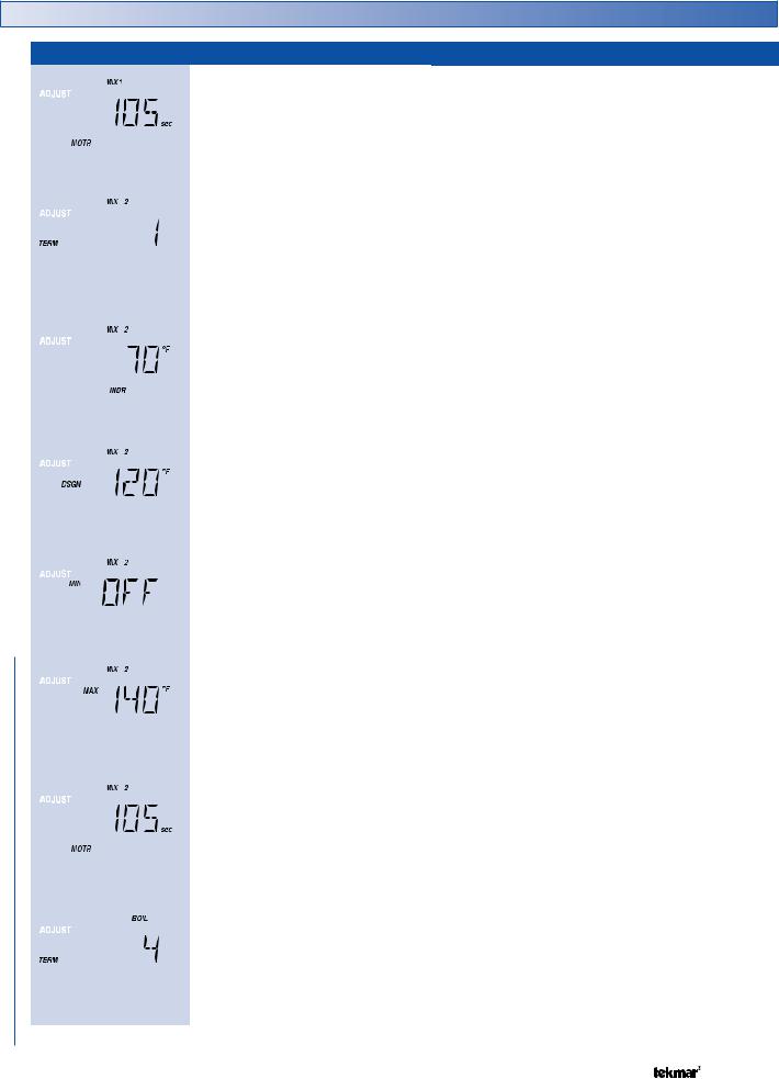
MIX 1 MOTOR |
SECTION G |
|
|
|
|
|
|
|
|
|
|
|
||
|
|
|
|
|
|
|
|
|
30 to 230 seconds |
|
The time that the Mix 1 actuating motor requires to |
|
|
|
|
|
|
|
|
|
|
|
|||
|
|
|
|
|
|
|
|
|
Ad |
operate from fully closed to fully open. |
|
|
|
|
|
|
|
|
|
|
|
Default = 105 |
|
||
|
|
|
|
|
|
|
|
|
|
Note: This item is only available when the Mix 1 |
||
|
|
|
|
|
|
|
|
|
|
|
||
|
|
|
|
|
|
|
|
|
|
|
Mode setting is set to floating action (FLt). |
|
|
|
|
|
|
|
|
|
|
|
|
|
|
|
|
|
|
|
|
|
|
|
1 HRF1 |
|
MIX 2 TERMINAL |
SECTION B |
|
|
|
|
|
|
|
|
|
2 HRF2 |
|
||
|
|
|
|
|
|
|
|
|
|
The type of heating terminal units that are being |
||
|
|
|
|
|
|
|
|
|
3 Fancoil |
InS |
||
|
|
|
|
|
|
|
|
|
4 Fin-tube Convector |
used in mix 2 zones. |
|
|
|
|
|
|
|
|
|
|
|
Ad |
|
||
|
|
|
|
|
|
|
|
|
5 Radiator |
Note: This item is only available when the tN4 DIP |
||
|
|
|
|
|
|
|
|
|
6 Baseboard |
|
||
|
|
|
|
|
|
|
|
|
|
switch is set to Mix 2. |
|
|
|
|
|
|
|
|
|
|
|
Default = 1 |
|
|
|
|
|
|
|
|
|
|
|
|
|
|
|
|
|
|
|
|
|
|
|
|
|
|
|
MIX 2 INDOOR |
SECTION B |
|
|
|
|
|
|
|
|
|
|
|
||
|
|
|
|
|
|
|
|
|
40 to 100°F |
|
The design indoor air temperature used in the heat |
|
|
|
|
|
|
|
|
|
|
|
|||
|
|
|
|
|
|
|
|
|
|
|||
|
|
|
|
|
|
|
|
|
|
loss calculation for mix 2 zones. Typically set to |
||
|
|
|
|
|
|
|
|
|
(4.5 to 38.0°C) |
Ad |
||
|
|
|
|
|
|
|
|
|
70°F (21.0°C). |
|
||
|
|
|
|
|
|
|
|
|
Default = 70°F (21.0°C) |
|
|
|
|
|
|
|
|
|
|
|
|
|
Note: This item is only available when the tN4 DIP |
||
|
|
|
|
|
|
|
|
|
|
|
||
|
|
|
|
|
|
|
|
|
|
|
switch is set to Mix 2. |
|
|
|
|
|
|
|
|
|
|
|
|
|
|
|
MENU |
|
|
|
|
|
|
|
|
|
|
|
|
|
|
|
|
|
|
70 to 220°F |
|
MIX 2 DESIGN |
SECTION B |
||
|
|
|
|
|
|
|
|
|||||
|
|
|
|
|
|
|
|
The supply water temperature required for the mix 2 |
||||
|
|
|
|
|
|
|
|
|||||
|
|
|
|
|
|
|
(21.0 to 104.5°C) |
InS |
||||
|
|
|
|
|
|
|
zones on the typical coldest day of the year. |
|||||
|
|
|
|
|
|
|
Default = 120°F |
Ad |
||||
|
|
|
|
|
|
|
Note: This item is only available when the tN4 DIP |
|||||
|
|
|
|
|
|
|
(49.0°C) |
|
||||
|
ADJUST |
|
|
|
|
|
|
|
|
switch is set to Mix 2. |
|
|
|
|
|
|
|
|
|
|
|
|
|
||
|
|
|
|
|
OFF, 40 to 150°F |
|
MIX 2 MINIMUM |
SECTION G |
||||
|
|
|
|
|
|
|||||||
|
|
|
|
|
|
|
|
|
|
|||
|
|
|
|
|
|
|
|
|
|
The minimum allowed mix 2 target temperature. |
||
|
|
|
|
|
|
|
|
|
(OFF, 4.5 to 65.5°C) |
Ad |
||
|
|
|
|
|
|
|
|
|
Note: This item is only available when the tN4 DIP |
|||
|
|
|
|
|
|
|
|
|
Default = OFF |
|
||
|
|
|
|
|
|
|
|
|
|
switch is set to Mix 2. |
|
|
|
|
|
|
|
|
|
|
|
|
|
|
|
|
|
|
|
|
|
|
|
|
|
|
|
|
|
|
|
|
|
|
|
|
|
|
|
|
|
|
|
|
|
|
|
|
|
|
80 to 220°F |
|
MIX 2 MAXIMUM |
SECTION G |
|
|
|
|
|
|
|
|
|
|
|||
|
|
|
|
|
|
|
|
|
|
|||
|
|
|
|
|
|
|
|
|
|
|||
|
|
|
|
|
|
|
|
|
|
|||
|
|
|
|
|
|
|
|
|
(26.5 to 104.5°C) |
Ad |
The maximum allowed mix 2 target temperature. |
|
|
|
|
|
|
|
|
|
|
Default = 140°F |
Note: This item is only available when the tN4 DIP |
||
|
|
|
|
|
|
|
|
|
|
|||
|
|
|
|
|
|
|
|
|
(60.0°C) |
|
switch is set to Mix 2. |
|
|
|
|
|
|
|
|
|
|
|
|
|
|
|
|
|
|
|
|
|
|
|
|
|
|
|
|
|
|
|
|
|
|
|
|
|
|
MIX 2 MOTOR |
SECTION G |
|
|
|
|
|
|
|
|
|
|
|
||
|
|
|
|
|
|
|
|
|
30 to 230 seconds |
|
The time that the mix 2 actuating motor requires to |
|
|
|
|
|
|
|
|
|
|
|
|||
|
|
|
|
|
|
|
|
|
|
|||
|
|
|
|
|
|
|
|
|
Ad |
operate from fully closed to fully open. |
|
|
|
|
|
|
|
|
|
|
|
Default = 105 |
Note: This item is only available when the tN4 DIP |
||
|
|
|
|
|
|
|
|
|
|
|||
|
|
|
|
|
|
|
|
|
|
|
switch is set to Mix 2. Availability also depends on |
|
|
|
|
|
|
|
|
|
|
|
|
the type of mixing module being used. |
|
|
|
|
|
|
|
|
|
|
|
|
|
|
|
|
|
|
|
|
|
|
|
|
|
|
|
|
|
|
|
|
|
|
|
|
1 HRF1 |
|
BOILER TERMINAL |
SECTION B |
|
|
|
|
|
|
|
|
|
2 HRF2 |
|
The type of heating terminal units that are being |
|
|
|
|
|
|
|
|
|
|
|
|||
|
|
|
|
|
|
|
|
|
3 Fancoil |
InS |
||
|
|
|
|
|
|
|
|
|
used in boiler zones. |
|
||
|
|
|
|
|
|
|
|
|
4 Fin-tube Convector |
|
||
|
|
|
|
|
|
|
|
|
Ad |
Note: This item is only available when the Boiler |
||
|
|
|
|
|
|
|
|
|
5 Radiator |
|||
|
|
|
|
|
|
|
|
|
6 Baseboard |
|
Sensor Sup / Ret DIP switch is set to Sup and the |
|
|
|
|
|
|
|
|
|
|
Default = 4 |
|
tN4 DIP switch is set to Boiler. |
|
|
|
|
|
|
|
|
|
|
|
|
||
|
|
|
|
|
|
|
|
|
|
|
|
|
 Continued on next page.
9 of 32 |
© 2007 |
D 422 - 08/07 |
Adjust Menu (3 of 5)
|
|
|
|
|
Item Field |
Range |
Access |
Description |
|
|
|
|
|
|
|
|
|
|
|
BOILER INDOOR |
SECTION B |
|
|
|
|
|
|
|
40 to 100°F |
|
The design indoor air temperature used in the heat |
|
|
|
|
|
|
|
|
|
|||
|
|
|
|
|
|
|
|
loss calculation for the boiler zones. Typically set to |
||
|
|
|
|
|
|
|
(4.5 to 38.0°C) |
|
||
|
|
|
|
|
|
|
Ad |
70°F (21.0°C). |
|
|
|
|
|
|
|
|
|
Default = 70°F |
|
||
|
|
|
|
|
|
|
|
Note: This item is only available when the Boiler |
||
|
|
|
|
|
|
|
(21.0°C) |
|
||
|
|
|
|
|
|
|
|
Sensor Sup / Ret DIP switch is set to Sup and the |
||
|
|
|
|
|
|
|
|
|
||
|
|
|
|
|
|
|
|
|
tN4 DIP switch is set to Boiler. |
|
|
|
|
|
|
|
|
|
|
|
|
|
|
|
|
|
|
|
70 to 220°F |
|
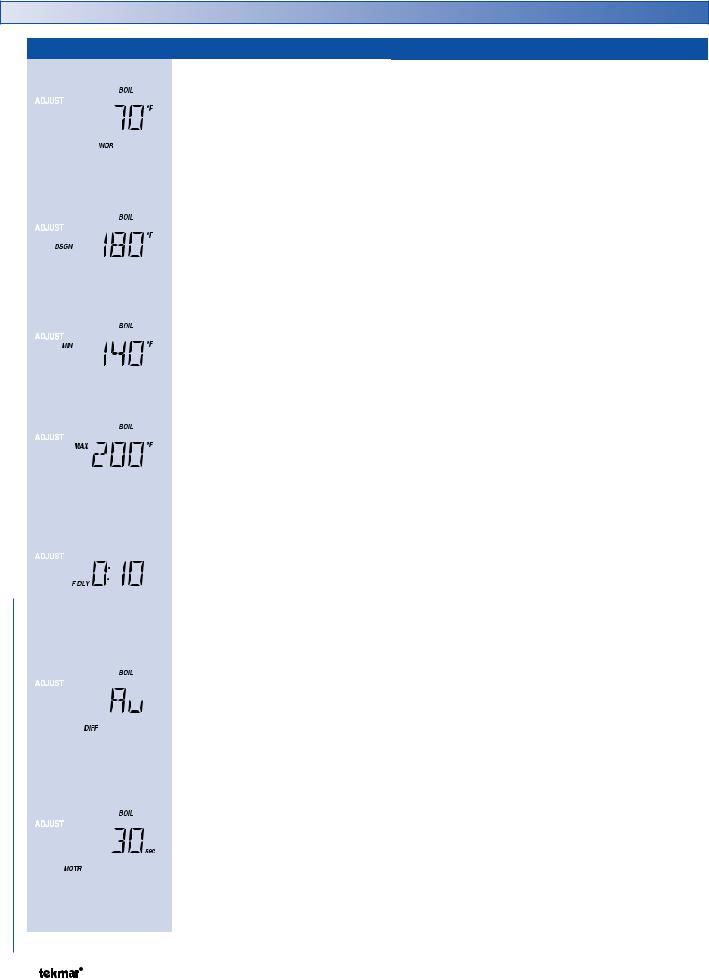
BOILER DESIGN |
SECTION B |
|
|
|
|
|
|
|
|
|||
|
|
|
|
|
|
|
|
The supply water temperature required for boiler |
||
|
|
|
|
|
|
|
|
|||
|
|
|
|
|
|
|
|
|||
|
|
|
|
|
|
|
(21.0 to 104.5°C) |
InS |
zones on the typical coldest day of the year. |
|
|
|
|
|
|
|
|
Default = 180°F |
Ad |
Note: This item is only available when the Boiler |
|
|
|
|
|
|
|
|
(82.0°C) |
|
Sensor Sup / Ret DIP switch is set to Sup and the |
|
|
|
|
|
|
|
|
|
|
tN4 DIP switch is set to Boiler. |
|
|
|
|
|
|
|
|
|
|
|
|
|
|
|
|
|
|
|
|
|
|
|
|
|
|
|
|
|
|
OFF, 80 to 180°F |
|
BOILER MINIMUM |
SECTION C |
|
|
|
|
|
|
|
|
|||
|
|
|
|
|
|
|
|
|||
|
|
|
|
|
|
|
|
The minimum allowed boiler target temperature and |
||
|
|
|
|
|
|
|
(OFF, 26.5 to 82.0°C) |
InS |
||
|
|
|
|
|
|
|
Default = 140°F |
Ad |
boiler return protection temperature. Check the boiler |
|
|
|
|
|
|
|
|
manufacturer’s manual for recommend supply water |
|||
|
|
|
|
|
|
|
(60.0°C) |
|
||
|
MENU |
|
|
|
|
|
temperatures. |
|
||
|
|
|
|
|
|
|
|
|||
|
|
|
|
|
|
|
|
|
||
|
|
|
|
|
120 to 225°F, OFF |
|
BOILER MAXIMUM |
SECTION C |
||
|
|
|
|
|
|
|||||
|
|
|
|
|
|
The maximum allowed boiler target temperature. |
||||
|
|
|
|
|
|
|||||
|
|
|
|
|
(49.0 to 107.0°C, OFF) |
|
||||
|
|
|
|
|
Ad |
Note: This item is only available when the Boiler |
||||
|
|
|
|
|
Default = 200°F |
|||||
|
|
|
|
|
|
|||||
|
ADJUST |
|
|
|
|
(93.5°C) |
|
Sensor Sup / Ret DIP switch is set to Sup and the |
||
|
|
|
|
|
0:00 to 3:00 min |
|
time that the relay contact closes to fire the boiler |
|||
|
|
|
|
|
|
|
|
|
tekmar stager DIP switch is set to OFF. |
|
|
|
|
|
|
|
|
|
|
FIRE DELAY |
SECTION C |
|
|
|
|
|
|
|
|
|
The time delay the control can expect between the |
|
|
|
|
|
|
|
|
|
|
||
|
|
|
|
|
|
|
Default = 0:10 min |
Ad |
and when the burner actually fires. |
|
|
|
|
|
|
|
|
|
Note: This item is only available when the Boiler |
||
|
|
|
|
|
|
|
|
|
||
|
|
|
|
|
|
|
|
|
Sensor Sup / Ret DIP switch is set to Sup and the |
|
|
|
|
|
|
|
|
|
|
tekmar stager DIP switch is set to OFF. |
|
|
|
|
|
|
|
|
|
|
|
|
|
|
|
|
|
|
|
|
|
BOILER DIFFERENTIAL |
SECTION C |
|
|
|
|
|
|
|
|
|
||
|
|
|
|
|
|
|
Au, 2 to 42°F |
|
The temperature differential that the control is to use |
|
|
|
|
|
|
|
|
|
|||
|
|
|
|
|
|
|
|
|||
|
|
|
|
|
|
|
|
when it is operating the boiler. |
|
|
|
|
|
|
|
|
|
(Au, 1 to 23.5°C) |
Ad |
|
|
|
|
|
|
|
|
|
Note: This item is only available when the Boiler |
|||
|
|
|
|
|
|
|
Default = Au |
|
||
|
|
|
|
|
|
|
|
Sensor Sup / Ret DIP switch is set to Sup and the |
||
|
|
|
|
|
|
|
|
|
||
|
|
|
|
|
|
|
|
|
tekmar stager DIP switch is set to OFF. |
|
|
|
|
|
|
|
|
|
|
||
|
|
|
|
|
|
|
|
|
|
|
|
|
|
|
|
|
|
|
|
BOILER MOTOR |
SECTION C |
|
|
|
|
|
|
|
|
|
The amount of time required for the modulating |
|
|
|
|
|
|
|
|
|
|
actuating motor to fully open the gas valve or operate |
|
|
|
|
|
|
|
|
|
|
||
|
|
|
|
|
|
|
10 to 230 seconds |
Ad |
the fan speed from a stopped position to full speed |
|
|
|
|
|
|
|
|
on a modulating boiler. |
|
||
|
|
|
|
|
|
|
Default = 30 seconds |
|
||
|
|
|
|
|
|
|
|
Note: This item is only available when the Boiler |
||
|
|
|
|
|
|
|
|
|
||
|
|
|
|
|
|
|
|
|
Sensor Sup / Ret DIP switch is set to Sup, the Boiler |
|
|
|
|
|
|
|
|
|
|
On-Off / Mod DIP switch is set to Mod and the tekmar |
|
|
|
|
|
|
|
|
|
|
stager DIP switch is set to OFF. |
|
|
|
|
|
|
|
|
|
|
|
|
 Continued on next page.
© 2007 |
D 422 - 08/07 |
10 of 32 |
 Loading...