


132
- Data Brochure
Pump Sequencer 132
D 132
04 /10
The Pump Sequencer 132 is designed to provide pump control for either stand-by or 2-stage operation. In stand-by mode, the 132
automatically switches over from the lead pump to the stand-by pump during a pump failure. In 2-stage mode, the 132 turns on the
second stage pump to meet additional flow requirements.
Additional functions include:
• Warm Weather Shut Down (WWSD)
• Exercising
• Equal Run Time Rotation
• Alert per Pump or Alert Levels
• Adjustable flow proof delay
• Test sequence to ensure proper component operation
• 120 V (ac) power supply
• CSA C US certified (approved to applicable UL standards)
Note:
Pump demand must
be powered with 20 to
260 V (ac) before the
pump will turn on.
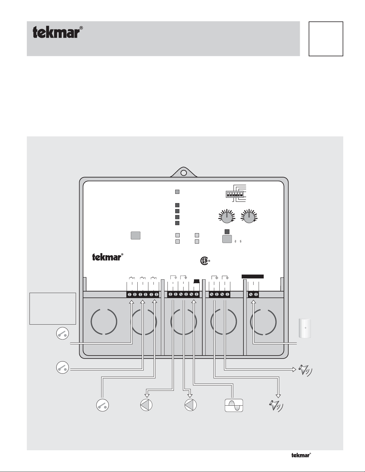
Input
Pump
Demand
Signal
Clear Alert
Pump Sequencer 132
Stand-by / 2-Stage
2
1
Use supply wires suitable for
120°F (50°C) above ambient
Pump
Demand
3
2-Stage
Demand
Pum p
1 2
Stand-by
70°F
Auto
Off
Power
WWSD
Pump Demand
2-Stage Demand
Flow Proof
Pump 1
Pump 2
Alert A
Alert B
35
WWSD
Test
Made in Canada by
tekmar Control Systems Ltd.
Power:
13 14
Alert
A
Pump Relays:
Alert Relays:
Demands:
15 16
Alert
A
B
B
US
89101112
4
5
Flow
Proof
7
6
Pump
1
Pump
Power
N
1
L
2
2
2-Stage
30 second Delay
Exercising
Alert per Pump
Alert Levels
Off
10 second Delay
96 hours
48
100
Off
Frequency of Rotation
off
red
red
120 V ± 10% 60 Hz 6 VA
240 V (ac) 10 A 1/2 hp, pilot duty 720 VA
240 V (ac) 10 A 1/3 hp, pilot duty 240 VA
20 to 260 V (ac) 2 VA
12
Off
not testing
testing
testing paused
Do not apply power
17 18
Outdoor
Sensor
144
168
Signal wiring
must be rate d
at least 300 V.
Meets Class B
Canadian ICES
FCC Part 15
H1197E
Input
Outdoor
Sensor
Optional
Input
2-Stage
Demand
Signal
Input
Flow Proof
Signal
Output
Output
PumpPump
Input
120 V (ac) Power
Supply
Output
Alert
Output
Alert
1 of 12 © 2010 D 132 - 04/10

How To Use The Data Brochure
-----------------------------------------------------------------------------------------------------------------
--------------------------------------------------------------------------------------------------------------------------------------------
--------------------------------------------------------------------------------------
This brochure is organized into three main sections. They are: 1) Sequence of Operation, 2) Installation, 3) Tro uble shooti ng. The
Sequence of Operation section has three sub-sections. We recommend reading Section A: General Operation of the Sequence of
Operation, as this contains important information on the overall operation of the control. Then read the sub-sections that apply to your
installation.
Table of Contents
Sequence of Operation ..................................Pg 2
Section A: General Operation ..............Pg 2
Settings ............................................................Pg 8
Testing the Control ......................................... Pg 9
Section B: Pump Operation .................. Pg 3
Error Messages ............................................... Pg 10
Section C: Alert Operation ...................Pg 4
Technical D ata .................................................Pg 12
Installa tion ....................................................... Pg 5
Limited Warranty ............................................Pg 12
Sequence of Operation
Section A
General Operation
Page 2 - 3
Section B
Pump Operation
Page 3 - 4
Section C
Alert Operation
Page 4
Section A: General Operation
POWERING UP THE CONTROL
When the Pump Sequencer 132 is powered up, a software version code is displayed for 2 seconds, then the control turns on all
of the red LED’s for 2 seconds. After this test, the control enters its normal operating mode. When the control is powered up, the
Power light remains on continuously.
-----------------------------------------------------------------------------------------------------------------
OPERATION
The Pump Sequencer 132 has two modes of operation. The 132 is capable of operating two pumps in either a stand-by or 2-stage
configuration.
Stand-by
In the stand-by mode of operation the 132 automatically switches over from the lead pump to the stand-by pump if the lead pump
fails to provide flow in the system.
2-Stage
In the 2-stage mode of operation the 132 turns on the second stage pump if there is a requirement for additional flow in the
system. At the same time the control still provides stand-by pump operation.
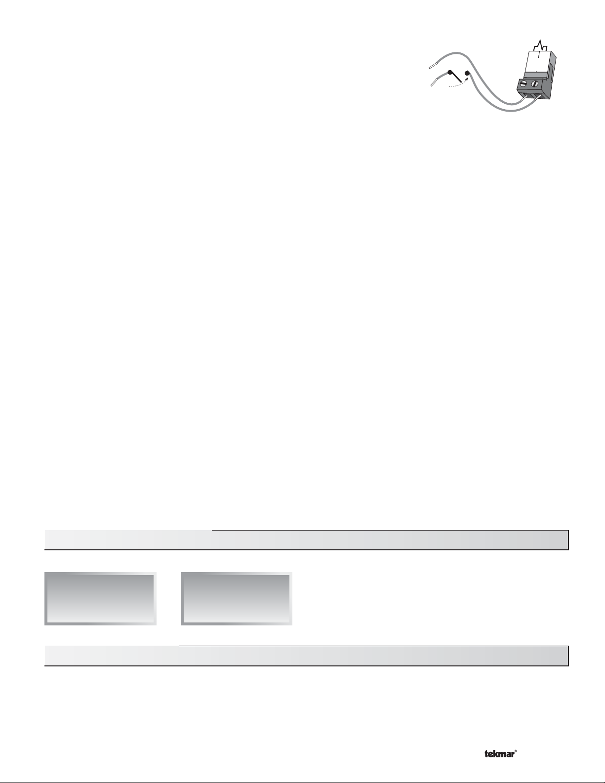
PUMP DEMAND
A pump demand is required in order for the 132 to provide flow. A pump demand is generated by applying a voltage between 24 and 240 V (ac) across the Pump Demand terminals
(1 and 2). Once voltage is applied, the Pump Demand light is turned on and the pump(s)
operate as required. A pump demand can be permanently powered, or generated from an
external source such as a manual switch or another control system.
© 2010 D 132 - 04/10 2 of 12
--------------------------------------------------------------------------------------------------------------------------------------------
----------------------------------------------------------------------------------------------------------------
-----------------------------------------------------------------------------------------------------------------
--------------------------------------------------------------------------------------
24 to 240 V (ac)
1
Pump
Demand
2
--------------------------------------------------------------------------
---------------------------------------------------------------------------------------------------------------------------------
----------------------------------------------------------------------------------------------------------------------------------------------
-------------------------------------------------------------------------------------------------------------------------------------------
----------------------------------------------------------------------------------------------------
----------------------------------------------------------------------------------------------------------------------------------
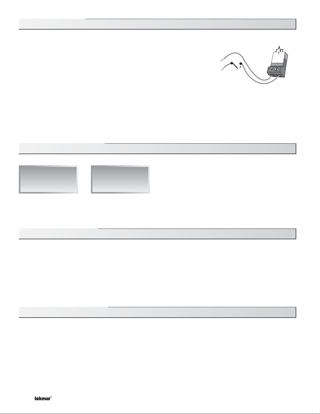
FLOW PROOF
-----------------------------------------------------------------------------------------
A flow proof signal is required at all times during pump operation. A flow proof is generated
by applying a voltage between 24 and 240 V (ac) across the Flow Proof terminals (5 and 6).
Once voltage is applied, the Flow Proof light is turned on. Once a pump contact is turned
on, a flow proof signal must be present before the flow proof delay has expired. A flow
proof can come from a flow switch, pressure differential switch, current sensing switch, or
power sensing switch.
-----------------------------------------------------------------------------------------
24 to 240 V (ac)
5
Flow
Proof
6
FLOW PROOF DELAY (30 second Delay / 10 second Delay)
The 132 allows a time delay for detecting a flow proof signal once a pump contact is turned on. The amount of time is adjustable
from 10 to 30 seconds through a DIP switch. If a flow proof signal is not present within the selected time, the control turns off the
first pump contact and turns on the second pump contact. An alert contact is activated to indicate the failure.
FLOW PROOF TEST
The 132 has a flow proof test in order to determine if the flow proof device has failed. Once the pump contacts are turned off, a flow
proof signal should not be present. If a flow proof signal is still present after 4 minutes, the control activates an alert contact and
displays an error message. Refer to the Error Messages section at the back of this brochure.
ROTATION
The 132 has a function which automatically changes the operating sequence of the pumps based on Equal Run Time Rotation.
Equal Run Time Rotation is based on pump running hours and allows for equal usage of both pumps. The 132 uses the Frequency
of Rotation dial to set the rotation of the pumps.
The control rotates the operating sequence of the pumps when the pumps are off. In a constant circulation system where the lead
pump runs continuously, the control waits for up to 12 hours to rotate the operating sequence of the pumps.
Note: The Equal Run Time Rotation function is reset by pressing the Clear Alert button.
EXERCISING
The 132 has a built-in pump exercising function. This function is only operational if the Exercising / Off DIP switch is set to
Exercising. If a pump has not been operated at least once every three days, the control turns on the output for 10 seconds. This
minimizes the possibility of a pump seizing during a long period of inactivity.
Note: The exercising function does not work if power to the control or pumps is off.
----------------------------------------------------------------------------------------------------------------------------------------------
-------------------------------------------------------------------------------------------------------------------------------------------
---------------------------------------------------------------------------------------------------------------------------------
--------------------------------------------------------------------------
WARM WEATHER SHUT DOWN (WWSD)
When the 132 is used as a stand alone control, the pumps can be operated based on outdoor air temperature. The WWSD feature
is only operational when an outdoor sensor is installed and the WWSD dial is not set to Off. When the outdoor air temperature rises
above the WWSD setting, the 132 turns on the WWSD light. When the control is in Warm Weather Shut Down, the demand LED’s
are displayed if there is a demand. However, the control does not operate the pumps to satisfy these demands. If the 132 receives
a pump demand from a reset control, the outdoor sensor should not be installed and the WWSD dial must be set to Off.
----------------------------------------------------------------------------------------------------
Section B: Pump Operation
Section B1
Stand-by
Section B2
2-Stage
Section B1: Stand-by
PUMP OPERATION
The lead pump contact closes whenever there is a pump demand and the 132 is not in WWSD. If a flow proof is not present after the
flow proof delay has expired, the control turns off the lead pump contact and turns on the stand-by pump contact. An alert contact
is activated to indicate the failure. The stand-by pump contact also turns off if a flow proof is not obtained once the flow proof delay
has expired.
3 of 12 © 2010 D 132 - 04/10
----------------------------------------------------------------------------------------------------------------------------------
----------------------------------------------------------------------------------
Section B2: 2-Stage
----------------------------------------------------------------------------------------------------------------------------------
-----------------------------------------------------------------------------------------------------------------------------
------------------------------------------------------------------------------------------------------------------------------------
2-STAGE DEMAND
A 2-stage demand is required in order for the 132 to provide additional flow. A 2-stage
demand is generated by applying a voltage between 24 and 240 V (ac) across the 2-Stage
Demand terminals (3 and 4). Once voltage is applied, the 2-Stage Demand light is turned
on. A 2-stage demand can come from an additional pressure differential switch, a temperature differential device, or a setpoint control based on an outdoor air temperature.
Note: The 2-stage demand device should provide an appropriate differential to prevent the
second stage pump from short cycling.
PUMP OPERATION
The first stage pump contact closes whenever there is a pump demand and the 132 is not in WWSD. The second stage pump contact closes whenever there is a pump demand, flow proof, 2-stage demand, and the 132 is not in WWSD.
If flow is not established by the first stage pump, the 132 turns off the first stage pump contact and turns on the second stage pump
contact. An alert contact is activated to indicate the failure. The second stage pump contact also turns off if a flow proof is not
obtained once the flow proof delay has expired.
Section C: Alert Operation
Section C1
Alert Levels
----------------------------------------------------------------------------------
3
4
2-Stage
Demand
24 to 240 V (ac)
----------------------------------------------------------------------------------------------------------------------------------
Section C2
Alert per Pump
There are two alert contacts (Alert A and Alert B) on the Pump Sequencer 132. These contacts are used to indicate either pump or
control failures. The alert contacts have two modes of operation. The mode of operation for the alert contacts is selected using the
Alert per Pump / Alert Levels DIP switch. When an alert contact is activated, refer to the Error Messages section of this brochure to
determine the cause of the alert signal. To clear an alert, press the Clear Alert button.
Section C1: Alert Levels
When operating in the Alert Levels mode, the alert contacts are used to indicate the level of failure in the system.
ALERT A (Non-Critical)
The Alert A contact closes when a non-critical failure occurs. Non-critical failures include: a single pump failure, a control error, an
outdoor sensor failure, or short cycling of the 2-stage demand. With these failures, it is still possible to establish flow in the system.
ALERT B (Critical)
The Alert B contact closes when a critical failure occurs. Critical failures include: the failure of both pumps, or a failure of the flow
proof device. With these failures, the control is no longer able to operate the pumps, and it is not possible to provide flow.
-----------------------------------------------------------------------------------------------------------------------------
------------------------------------------------------------------------------------------------------------------------------------
Section C2: Alert per Pump
When operating in Alert per Pump mode, the alert contacts are related to the pump contacts on the control. The Alert A contact closes
anytime Pump 1 fails, and the Alert B contact closes anytime Pump 2 fails. The Alert A contact also closes to indicate an outdoor
sensor failure, a control error, a flow proof device failure, or if the 2-stage demand is short cycling.
© 2010 D 132 - 04/10 4 of 12
 Loading...