


263
- Data Brochure
Boiler Control 263
D 263
03/09
The tekmar Boiler Control 263 can control the supply water temperature from a single modulating boiler or up to 2 on / off stages
based on outdoor temperature, domestic hot water requirements, or setpoint requirements. A large easy to read display provides
current system temperatures and operating status. The control has an internal setback timer, which can have 2 events per day on a
24 hour, 5-1-1 day or 7 day schedule.
Additional functions include:
• Outdoor Reset
• Installer and Advanced access levels
• Primary pump output
• Pump exercising
• Pump purging
• Boiler demand for space heating loads
• DHW demand for domestic hot water loads
Note:
Boiler, DHW, or
setpoint demand
must be powered
with 20 to 260 V (ac)
before the boiler is
able to fire.
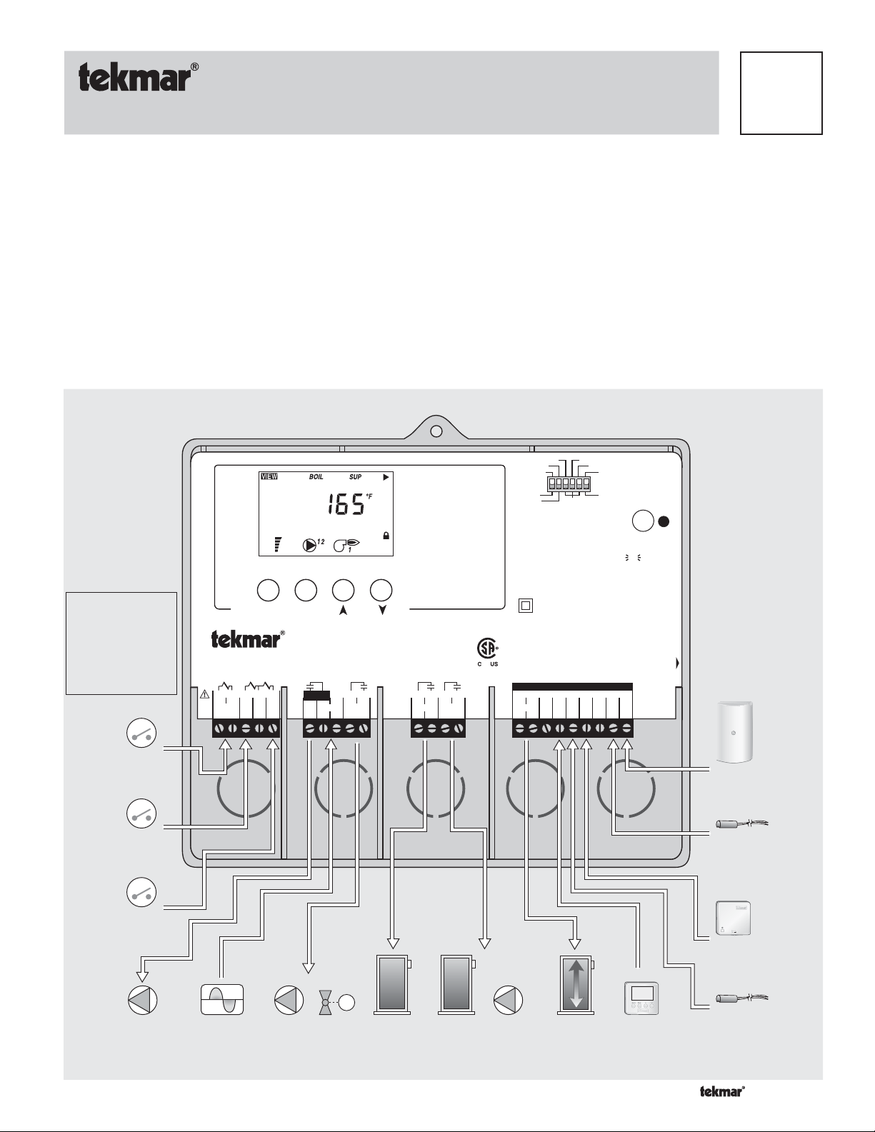
Menu Item
Boiler Control 263
Two Stage / One Modulating Boiler, DHW & Setpoint
1 2 3
4
5
Boiler
Demand
DHW
Dem
Com
Dem
6 7NL8
Setp
Prim
Dem
Power
P1
• Setpoint demand for setpoint loads
• Optional indoor sensor for room air temperature control
• Test sequence to ensure proper component operation
• Internal setback timer for energy savings
• Setback input for energy savings
• CSA C US certified
Soft Stop
Setback
Boiler Demand
DHW Demand
Setpoint Demand
Modulation
Priority Override
9 10 11 12113114 15+16-17 18 19 20 21 22 23
DHW
Pmp/Vlv
Relay
Relay Mod 1 mA
2/P2
Advanced
Installer
None
Modes
1 Two On/Off Stages
2 One Modulating Boiler and Pump
Made in Canada by
tekmar Control Systems Ltd.
Power 115 V ±10% 50/60 Hz 600 VA
Relays 230 V (ac) 5 A 1/3 hp, pilot duty 240 VA
Demands 20 to 260 V (ac) 2 VA
Signal wiring must be rated at least 300 V.
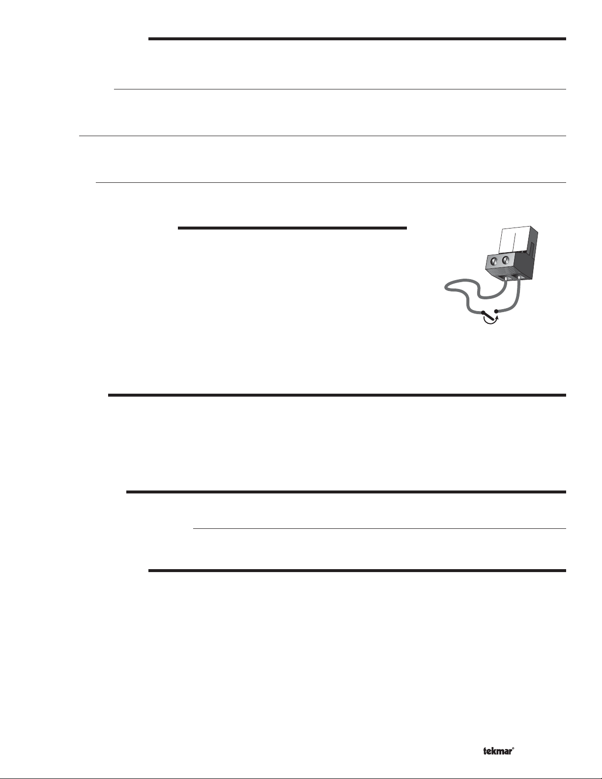
Rotate
DHW Sensor
Off
Exercise
Off
Test
Do not apply power
Com Com Boil Out
DHW Indr
UnO
Sw
off not testing
testing
red
testing paused
red
For maximum
heat press &
hold Test for 3
seconds.
Meets Class B:
Canadian ICES
FCC Part 15
Date Code
H2038B
Input
Boiler
Demand
Input
DHW
Demand
Input
Setpoint
Demand
OR OR
Input
Outdoor
Sensor
Included
Input
Universal
Sensor
Included
Input
Indoor
Sensor
Optional
M
Input
Output
Primary
Pump
Input
115 V (ac)
Power Supply
Output
DHW Pump or
DHW Valve
Output
Boiler
Output
Boiler
Output
Pump
Output
Boiler
Output
tekmar
Timer
1 of 36 © 2009 D 263 - 03/09
Universal
Sensor
Optional
How To Use The Data Brochure
This brochure is organized into four main sections. They are: 1) Sequence of Operation, 2) Installation, 3) Control Settings, and 4)
Testing and Troubleshooting. The Sequence of Operation section has six sub-sections. We recommend reading Section A: General
of the Sequence of Operation, as this contains important information on the overall operation of the control. Then read the sub
sections that apply to your installation.
The Control Settings section (starting at DIP Switch Settings) of this brochure describes the various items that are adjusted and
displayed by the control. The control functions of each adjustable item are described in the Sequence of Operation.
Table of Contents
User Interface ..................................................Pg 2
Display ............................................................. Pg 3
Sequence of Operation ..................................Pg 4
Section A: General Operation .............. Pg 4
Section B: Boiler Operation.................. Pg 6
Section C: Pump Operation .................. Pg 11
Section D: Boiler Reset Operation ......Pg 12
Section E: DHW Operation ...................Pg 14
Section F: Setpoint Operation ..............Pg 17
Installa tion ....................................................... Pg 18
DIP Switch Settings ........................................Pg 25
Control Settings ..............................................Pg 26
View Menu ..............................................Pg 26
Adjust Menu ...........................................Pg 27
Time Menu .............................................. Pg 30
Schedule Menu ......................................Pg 31
Testing the Control ......................................... Pg 32
Error Messages ...............................................Pg 33
Technical Data .................................................Pg 36
Limited Warranty ............................................Pg 36
User Interface
The control uses a Liquid Crystal Display (LCD) as the method of supplying information. You use the LCD in order to setup and
monitor the operation of your system. The control has four push buttons (Menu, Item, ▲, ▼) for selecting and adjusting settings. As
you program your control, record your settings in the ADJUST menu table, which is found in the second half of this brochure.
Menu
All of the items displayed by the control are organized into four menus (View, Adjust,
Time, Schedule). These menus are listed on the top left hand side of the display (Menu
Field). To select a menu, use the Menu button. By pressing and releasing the Menu
button, the display sequences between the four menus. Once a menu is selected, there
will be a group of items that can be viewed within the menu.
Menu Item
Item
The abbreviated name of the selected item will be displayed in the item field of the
display. To view the next available item, press and release the Item button. Once you
have reached the last available item in a menu, pressing and releasing the Item button
will return the display to the first item in the selected menu.
The items can be quickly scrolled through by holding the Item button and then pressing
the ▼ button. To rapidly scroll through the items in the reverse order, hold the Item
button and press the ▲ button.
Adjust
To make an adjustment to a setting in the control, begin by selecting the ADJUST, TIME
or SCHEDULE menu using the Menu button. Then select the desired item using the
Item button. Finally, use the ▲, and / or ▼ button to make the adjustment.
Additional information can be gained by observing the Status field of the LCD. The status
field will indicate which of the control’s outputs are currently active. Most symbols in the
status field are only visible when the VIEW menu is selected.
.
© 2009 D 263 - 03/09 2 of 36
Menu Item
Menu Item
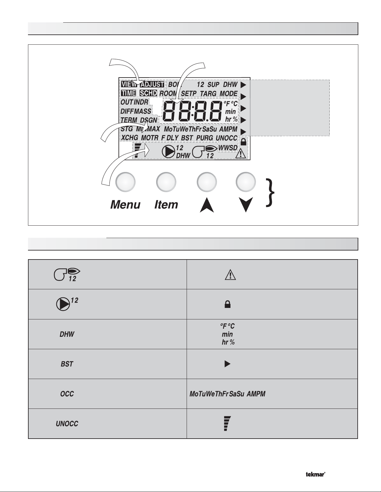
Display
Menu Field
Displays the
current menu
Item Field
Displays an
abbreviated
name of the
selected item
Status Field
Displays the
current status
of the control's
inputs, outputs
and operation
Number Field
Displays the current value
of the selected item
Boiler Demand
DHW Demand
Setpoint Demand
Modulation
Priority Override
Buttons
Selects Menus, Items
and adjust settings
Symbol Description
Burner
Displays when Relay 1
and / or Relay 2 is turned on.
Pump
Displays when the primary or
boiler pump is operating.
DHW
Displays when the DHW
pump is on.
Boost
Displays when the control is
in boost after setback.
Occupied Schedule
Displays when the control is
in occupied mode.
UnOccupied Schedule
Displays when the control is
in unoccupied mode.
Warning
Displays when an error exists or
when a limit has been reached.
Lock / Unlock
Displays when the Advanced /
Installer DIP switch is set to
Installer.
°F, °C, min, hr, %
Units of measurement.
Pointer
Displays the control operation
as indicated by the text.
Day of Week
Displays the day of the week and
indicates morning or afternoon.
Modulating Output Scale
Displays the total modulation
output level of the boiler.
3 of 36 © 2009 D 263 - 03/09
Definitions
The following defined terms and symbols are used throughout this manual to bring attention to the presence of hazards of various risk
levels, or to important information concerning the life of the product.
- Warning Symbol: Indicates presence of hazards which can cause severe personal injury, death or
substantial property damage if ignored.
INSTALLATION
CATEGORY II
- Double insulated
- Local level, appliances
Sequence of Operation
Section A
General
Operation
Page 4 - 5
Section F
Setpoint
Operation
Page 17 - 18
Section B
Boiler
Operation
Page 6 - 10
Section C
Pump
Operation
Page 11
Section D
Boiler Reset
Operation
Page 12 - 14
Section E
DHW
Operation
Page 15 - 17
Section A: General Operation
POWERING UP THE CONTROL
When the control is powered up, all segments in the LCD are turned on for 2 seconds. Next, the control displays the control type
number in the LCD for 2 seconds. Next, the software version is displayed for 2 seconds. Finally, the control enters into the normal
operating mode.
OPERATING MODES
The control operates in two different operating modes:
Mode 1 – Two ON / OFF Stages
Mode 1 operates up to two on / off boilers or one boiler with two stages.
Mode 2 – One Modulating Boiler & Pump
Mode 2 operates one modulating boiler and the boiler pump.
Primary
Pump
Primary
Pump
DHW
Pump
Sensor
DHW
Pump
Boiler
Sensor
Boiler
Boiler
Pump
© 2009 D 263 - 03/09 4 of 36
TYPES OF DEMANDS
The control stages or modulates the boiler(s) to control supply water temperature to a hydronic system. The supply water temperature
is based on outdoor reset, a fixed temperature for DHW, or a fixed temperature for setpoint.
Boiler Reset
When a boiler demand signal from the heating system is present, the control operates the boiler(s) to maintain the supply
temperature based on the outdoor air temperature and the Characterized Heating Curve settings. Refer to section D.
DHW
When a DHW demand is present, the control operates the boiler(s) to maintain the supply water temperature at least as hot as
the DHW exchange setting or high enough to satisfy tank temperature. Refer to section E.
Setpoint
When a setpoint demand signal is present, the control operates the boiler(s) to maintain the supply water temperature at least as
hot as the Setpoint setting. Refer to section F.
SETBACK (Occ and UnOcc)
To provide greater energy savings, the control has a setback feature. With setback, the
supply water temperature in the system is reduced when the building is unoccupied. By
17
Com
UnO
Sw
18
reducing the supply water temperature, the air temperature in the space may be reduced
even when thermostat(s) are not turned down.
The control has an internal setback timer with two events per day on either a 24 hour, a
5-1-1 day or a 7 day schedule.
The control also has an external setback input. Any time the UnO Sw (18) and t he Com (17)
Timer Switch
are shorted together, the control operates in the unoccupied mode.
The external setback overrides the internal setback timer schedule to place the control into the unoccupied period.
When in the unoccupied mode, the UNOCC segment is displayed in the LCD. The control adjusts the supply water temperature
based on the UNOCC settings made in the control.
EXERCISING
The control has a built-in exercising feature that is selected through the Exercise / Off DIP switch. To enable the exercising feature
set the Exercise / Off DIP switch to Exercise. If exercising is enabled, the control ensures that each pump is operated at least
once every 3 days. If a pump has not been operated at least once every 3 days, the control turns on the output for 10 seconds.
This minimizes the possibility of the pump seizing during a long period of inactivity. While the control is exercising, the Test LED
flashes quickly.
Note: The exercising function does not work if power to the control or pumps is disconnected.
RUNNING TIMES
The control displays the accumulated running time of each boiler in the VIEW menu.
Resetting the Running Times
To reset the running time for each boiler, select the appropriate running time in the VIEW menu. Next press the ▲ and ▼ buttons
simultaneously until CLR is displayed.
FACTORY D EFAULTS
The control comes preset with several factory defaults. These are based on the terminal unit selection. To fine-tune building
requirements, these defaults may be changed.
To reload the factory default, power down the control and wait for 10 seconds. Power up the control while simultaneously holding the
Menu and ▼ buttons. An E01 error occurs forcing the installer to go through the ADJUST menu to ensure the settings are correct.
5 of 36 © 2009 D 263 - 03/09
Section B: Boiler Operation
Section B1
Boiler
Operation
Section B2
Mode 1
Two St age
Operation
Section B3
Mode 2
Modulating
Boiler Operation
Section B1: Boiler Operation
BOILER TARGET TEMPERATURE
The boiler target temperature is determined by the type of demand received by the control. A boiler demand calculates a boiler
target based on the characterized heating curve settings and the outdoor air temperature. A DHW demand and a Setpoint demand
have temperature settings to which the boilers are operated to meet.
The control displays the temperature that it is currently trying to maintain as the boiler supply temperature. If the control does not
presently have a requirement for heat, it does not show a boiler target temperature. Instead, “– – –” is displayed in the LCD.
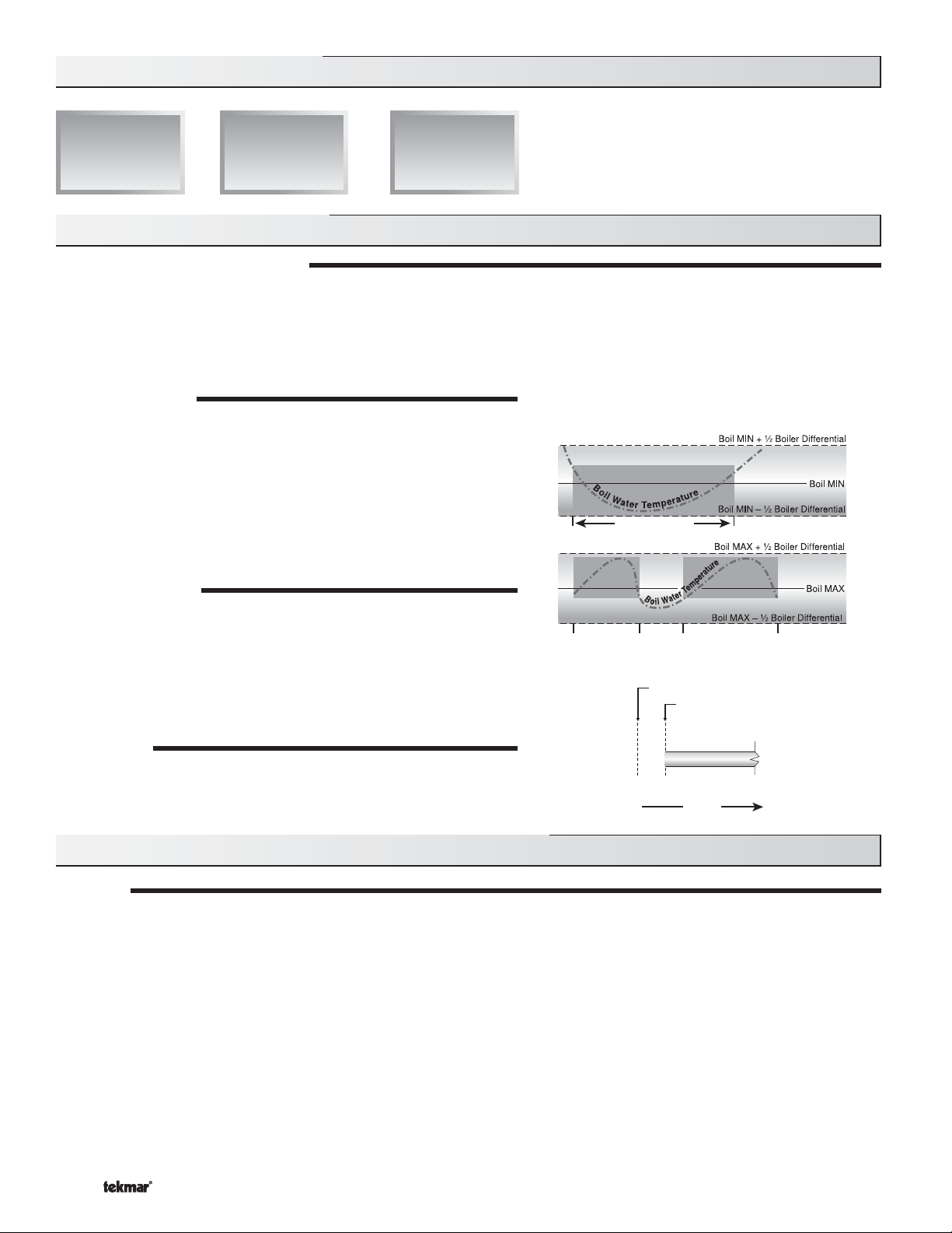
BOILER MINIMUM
The boiler minimum is the lowest temperature that the control is
allowed to use as a boiler target temperature. During mild conditions,
if the control calculates a boiler target temperature that is below the
Boiler Minimum setting, the boiler target temperature is adjusted to at
least the Boiler Minimum setting. During this condition, if the boiler(s) is
operating, the minimum segment is turned on in the display when viewing
either the boiler supply temperature or the boiler target temperature. Set
the Boiler Minimum setting to the boiler manufacturer’s recommended
temperature.
MIN Segment On
BOILER MAXIMUM
The boiler maximum is the highest temperature that the control is
allowed to use as a boiler target temperature. If the control does target
the Boiler Maximum setting, and the boiler temperature is near the boiler
MAX Segment
On
MAX Segment
On
maximum temperature, the maximum segment will be displayed in the
LCD while either the boiler target temperature or the boiler temperature
is being viewed. At no time does the control operate the boiler(s) above
248°F (120°C).
Boiler
Contact Closes
Boiler
Fires
FIRE DELAY
The Fire Delay is the time delay that occurs between the time that the control
closes a stage contact to fire a stage and the burner fires for that stage.
Fire
Delay
Time
Section B2: Mode 1 - Two On / Off Stages Operation
STAGING
When operating in mode 1, the control operates up to two on / off stages in order to provide the required supply temperature. After
a stage is turned on in the firing sequence, the control waits for a minimum time delay. The minimum time delay is adjustable using
the Stage Delay setting. After the Stage Delay has expired, the control examines the control error to determine when the next stage
is to fire. The control error is determined using Proportional, Integral and Derivative (PID) logic.
Proportional compares the actual supply temperature to the boiler target temperature. The colder the supply water temperature,
the sooner the next stage is turned on.
Integral compares the actual supply temperature to the boiler target temperature over a period of time.
Derivative compares how fast or slow the supply water temperature is changing. If the supply temperature is increasing
slowly, the next stage is turned on sooner. If the supply temperature is increasing quickly, the next stage is turned
on later, if at all.
© 2009 D 263 - 03/09 6 of 36
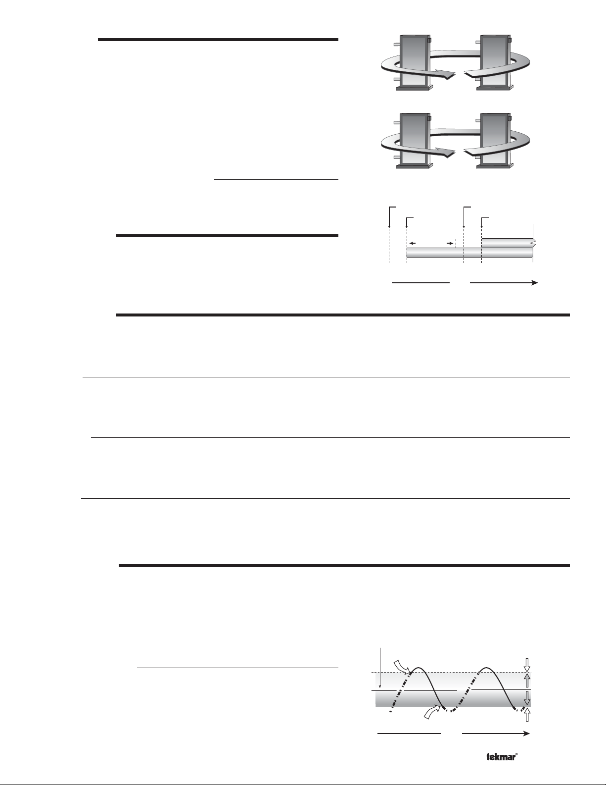
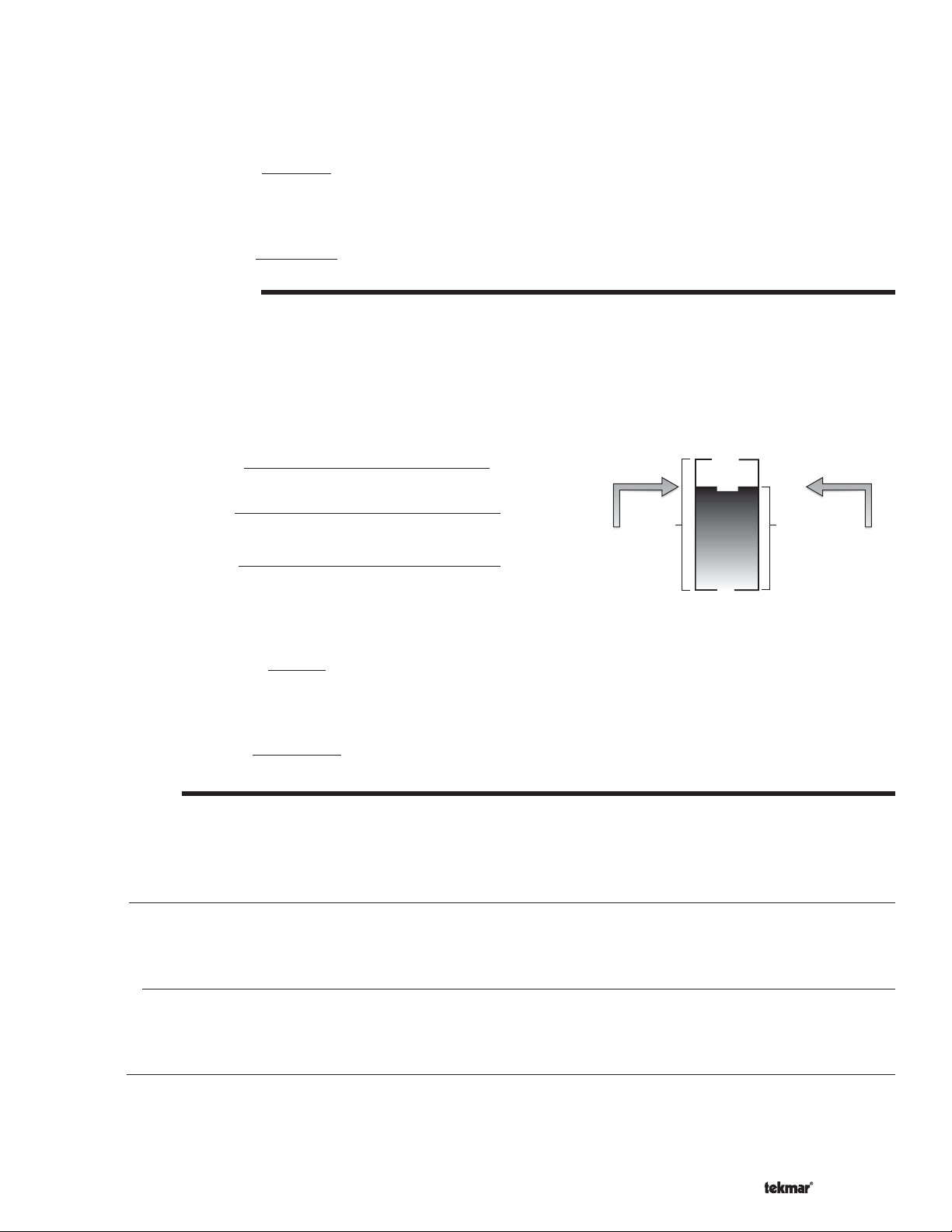
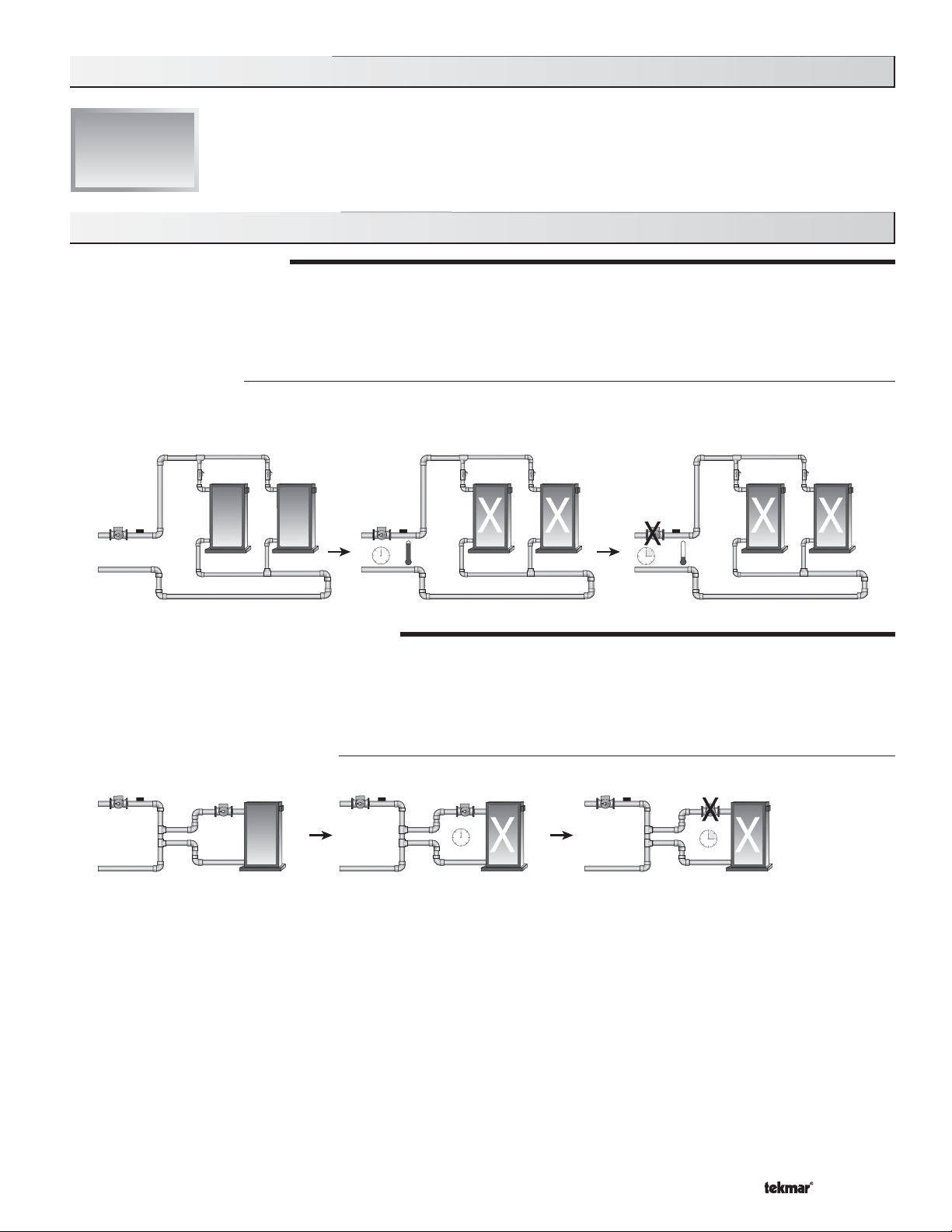
ROTATION
The control’s Equal Run Time Rotation function is fixed at 48 hours. The
firing order of the boilers changes whenever one boiler accumulates 48
hours more running time than the other boiler. After each rotation, the
boiler with the least running hours is the first to fire and the boiler with
the most running hours is the last to fire. This function ensures that both
boilers receive equal amounts of use. When the Rotate / Off DIP switch
is set to the Off position, the firing sequence always begins with boiler
one and then boiler two.
Note: When using a single two-stage boiler, ensure that the Rotate / Off
DIP switch is set to Off.
12
720 hours 672 hours
21
Resetting the Rotation Sequence
672 hours 720 hours
To reset the rotation sequence, set the Rotate / Off DIP switch to
the Off setting for 5 seconds and then return the DIP switch to the
Rotate setting.
STAGE DELAY
The stage delay is the minimum time delay between the firing of stages.
After this delay has expired the control can fire the next stage if it is
required. This setting can be adjusted manually or set to an automatic
setting. When the automatic setting is used, the control determines the
Boiler 1
Contact Closes
Fire
Delay
Boiler 1
Fires
Stage Delay
Time
Boiler 2
Contact Closes
Fire
Delay
Boiler 2
Fires
best stage delay based on the operation of the system.
BOILER MASS
The Boiler Mass setting allows the installer to adjust the control to the thermal mass of the type of heat sources used in the
application. If the heating system is causing the boiler(s) to be staged on and off in rapid succession, a higher Boiler Mass setting
will result in a decrease in the amo unt of cycling. Conversely, if t he system is s low to resp ond to heat requiremen ts, then dec reasing
the Boiler Mass setting will increase the response rate by staging the boilers at a faster rate.
Lo (1)
The Lo setting is selected if the boiler(s) that is used has a low thermal mass. This means that the boiler(s) has a very small water
content and has very little metal in the heat exchanger. A boiler that has a low thermal mass comes up to temperature quite
rapidly when fired. This is typical of many copper fin-tube boilers. The Lo Mass setting provides a fast staging rate of additional
on / off boiler stages.
Med (2)
The Med setting is selected if the boiler(s) that is used has a medium thermal mass. This means that the boiler(s) either has a
large water content and a low metal content or a small water content and a high metal content. This is typical of many modern
residential cast iron boilers or steel tube boilers. The Med Mass setting provides a moderate staging rate of additional on / off
boiler stages.
Hi (3)
The Hi setting is selected if the boiler(s) that is used has a high thermal mass. This means that the boiler(s) has both a large water
content and a large metal content. A boiler that has a high thermal mass is relatively slow in coming up to temperature. This is
typical of many commercial cast iron and steel tube boilers. The Hi Mass setting provides a slow staging rate of additional on / off
boiler stages.
DIFFERENTIAL
An on / off heat source must be operated with a differential in order to prevent short cycling. With the control, either a fixed or an
auto differential may be selected. The boiler differential is divided around the boiler target temperature. The stage contact closes
when the supply water temperature is ½ of the differential setting below the boiler target temperature. Additional staging occurs if
the first stage is unable to raise the supply water temperature up to the boiler target temperature at a reasonable rate. As the supply
temperature reaches ½ of the differential above the boiler target temperature, stages are staged off.
Desired temperature
160°F (71°C)
Boiler Off
Boiler On
165°F (74°C)
e
r
u
t
a
r
e
p
m
e
T
155°F (68°C)
e
s
i
r
Fixed Differential
If the user desires to have a fixed differential, this is set using the
Boiler Differential setting in the ADJUST menu.
Time
7 of 36 © 2009 D 263 - 03/09
T
e
m
p
Differential
10°F (6°C)
e
r
a
t
u
r
e
f
a
l
l
Auto Differential
Off
If the Auto Differential is selected, the control automatically determines
the best differential as the load changes. This reduces potential short
cycling during light load conditions.
Differential
On
Increasing Load
Time
Section B3: Mode 2 - One Modulating Boiler and Pump Operation
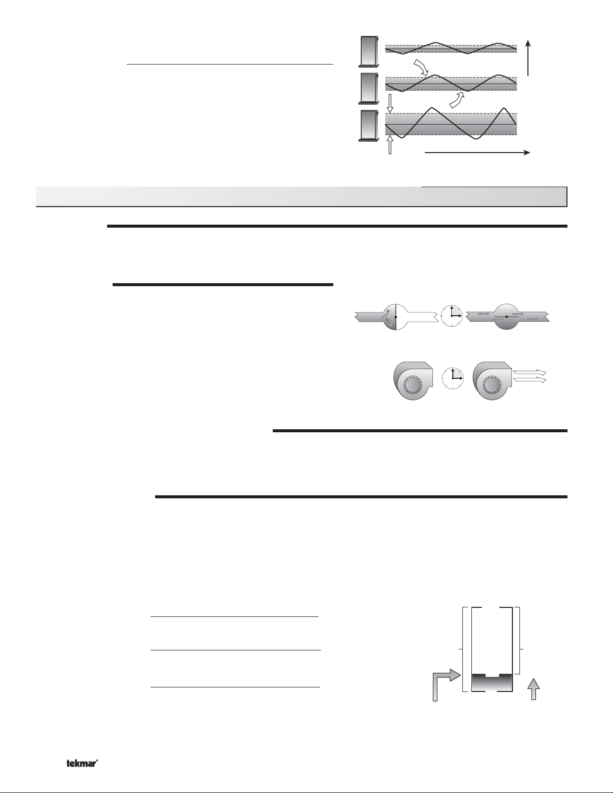
MODULATION
When operating in Mode 2, the control provides a modulating output signal to operate a single modulating boiler. The control first
closes the boiler contact on to ignite the ignition sequence. The boiler is then modulated from the minimum modulation using
Proportional, Integral and Derivative (PID) logic in order to satisfy the boiler target temperature.
MOTOR SPEED
The Motor Speed is the amount of time the boiler requires to go from 0%
modulation to 100% modulation.
Gas valve actuating motors have a design time from fully closed to
fully open which can be found in the manufacturer’s manual. The
Motor Speed should be set to this time.
The Motor Speed setting for a Variable Frequency Drive (VFD) is the
amount of time required to go from a stopped position to 100% fan
speed. Since a VFD has a very quick response rate, it may be necessary
to increase the Motor Speed setting in order to increase the stability of
the boiler modulation.
MODULATION RANGE (4 to 20 mA or 0 to 20 mA)
The modulation output (Mod 1) can be adjusted from a 4 to 20 mA output range or to a 0 to 20 mA output range using the
Boil Modulation setting. The resulting modulation output signal can be converted to a 0 to 5 V (dc), 1 to 5 V (dc), 0 to 10 V (dc), and
2 to 10 V (dc) output using external resistors. The modulation output signal can be converted to a 0 to 135 Ω (W R B) output using
a 0 to 135 Ω Converter 005. Refer to the Modulation Output section in Step 4 of the Installation section.
MINIMUM MODULATION
The minimum modulation defines the minimum output signal from the control to the boiler burner. It is based on a percentage of
the control’s output signal range.
The Minimum Modulation setting for boilers with power burners is typically set to 0%.
For boilers with electronic operators, the boiler’s input signal range may not match the output signal range of the 263 control. The
Minimum Modulation setting limits the control output range in order to match the boiler’s input range.
To calculate the Minimum Modulation, use the following formulae:
For 4 to 20 mA:
Minimum Modulation =
4 mA – Boiler’s Minimum Input Signal
4 - 20 mA
For 0 to 10 V (dc):
Minimum Modulation =
0 V (dc) – Boiler’s Minimum Input Signal
0 – 10 V (dc)
For 2 to 10 V (dc):
Minimum Modulation =
2 V (dc) – Boiler’s Minimum Input Signal
2 – 10 V (dc)
x 100%
x 100%
x 100%
MINIMUM MODULATION
Control's
Output
Signal
Range
Minimum
Modulation
100%10 V (dc) 10 V (dc)
Boiler's
Input
Signal
Range
18%
0%0 V (dc)
1.8 V (dc)
Boiler's Minimum
Input Signal
© 2009 D 263 - 03/09 8 of 36
Example 1:
A boiler requires a 1.8 V (dc) signal to fire the boiler at low fire. The boiler can be modulated to 10 V (dc) where it reaches high fire.
This means the boiler’s input signal range is 1.8 to 10 V (dc). The 263 control has an output signal range of 0 to 20 mA which can be
externally converted to 0 to 10 V (dc) using a 500 Ω resistor (Refer to Modulation Output section in Step 4 of the Installation section).
To make the two signal ranges the same, the Minimum Modulation required is:
Minimum Modulation
=
0 V – 1.8 V
0 V – 10 V
x 100% = 18%
Example 2:
If the boiler’s input signal range is 6 to 20 mA the required Minimum Modulation is:
Minimum Modulation =
4 mA – 6 mA
4 mA – 20 mA
x 100% = 13%
MAXIMUM MODULATION
The maximum modulation defines the maximum output signal from the control to the boiler burner. It is based on a percentage of
the control’s output signal range.
The Maximum Modulation setting for boilers with power burners is typically set to 100%.
For boilers with electronic operators, the boiler’s input signal range may not match the output signal range of the 263 control. The
Maximum Modulation setting limits the control output range in order to match the boiler’s input range.
To calculate the Maximum Modulation, use the following formulae:
For 4 to 20 mA:
Maximum Modulation =
4 mA – Boiler’s Maximum Input Signal
4 – 20 mA
x 100%
For 0 to 10 V (dc):
Maximum Modulation =
For 2 to 10 V (dc):
Maximum Modulation =
0 V (dc) – Boiler’s Maximum Input Signal
0 – 10 V (dc)
2 V (dc) – Boiler’s Maximum Input Signal
2 – 10 V (dc)
x 100%
x 100%
Maximum
Modulation
Example 1:
A boiler’s input signal range is 2 to 9 V (dc). The 263 control has an output signal range of 2 to 10 V (dc).
To make the two signal ranges the same, the Maximum Modulation required is:
Maximum Modulation =
2 V – 9 V
2 V – 10 V
x 100% = 88%
MAXIMUM MODULATION
Control's
Output
Signal
Range
100%10 V (dc)
88%
9 V (dc)
Boiler's
Input
Signal
Range
0%2 V (dc)
2 V (dc)
Boiler's
Maximum
Input Signal
Example 2:
If the boiler’s input signal range is 6 to 19 mA the required Maximum Modulation is:
Maximum Modulation =
4 mA – 19 mA
4 mA – 20 mA
x 100% = 94%
BOILER MASS
The Boiler Mass setting allows the installer to adjust the control to the thermal mass of the type of heat sources used in the
application. The modulation of the boiler can become unstable if the incorrect Boiler Mass setting is chosen. A key sign of the boiler
modulation being unstable is the flame will continue to increase and then decrease in short periods of time. By choosing a lower
Boiler Mass setting, the boiler response will become more stable.
Lo (1)
The Lo setting is selected if the boiler that is used has a low thermal mass. This means that the boiler has a very small water
content and has very little metal in the heat exchanger. A boiler that has a low thermal mass comes up to temperature quite rapidly
when fired. This is typical of many copper fin-tube boilers. The Lo Mass setting provides a fast response to the heating system.
Med (2)
The Med setting is selected if the boiler that is used has a medium thermal mass. This means that the boiler either has a large
water content and a low metal content or a low water content and a high metal content. This is typical of many modern residential
cast iron boilers or steel tube boilers. The Med Mass setting provides a moderate response to the heating system.
Hi (3)
The Hi setting is selected if the boiler that is used has a high thermal mass. This means that the boiler has both a large water
content and a large metal content. A boiler that has a high thermal mass is relatively slow in coming up to temperature. This is
typical of many commercial cast iron and steel tube boilers. The Hi Mass setting provides a slow response to the heating system.
9 of 36 © 2009 D 263 - 03/09
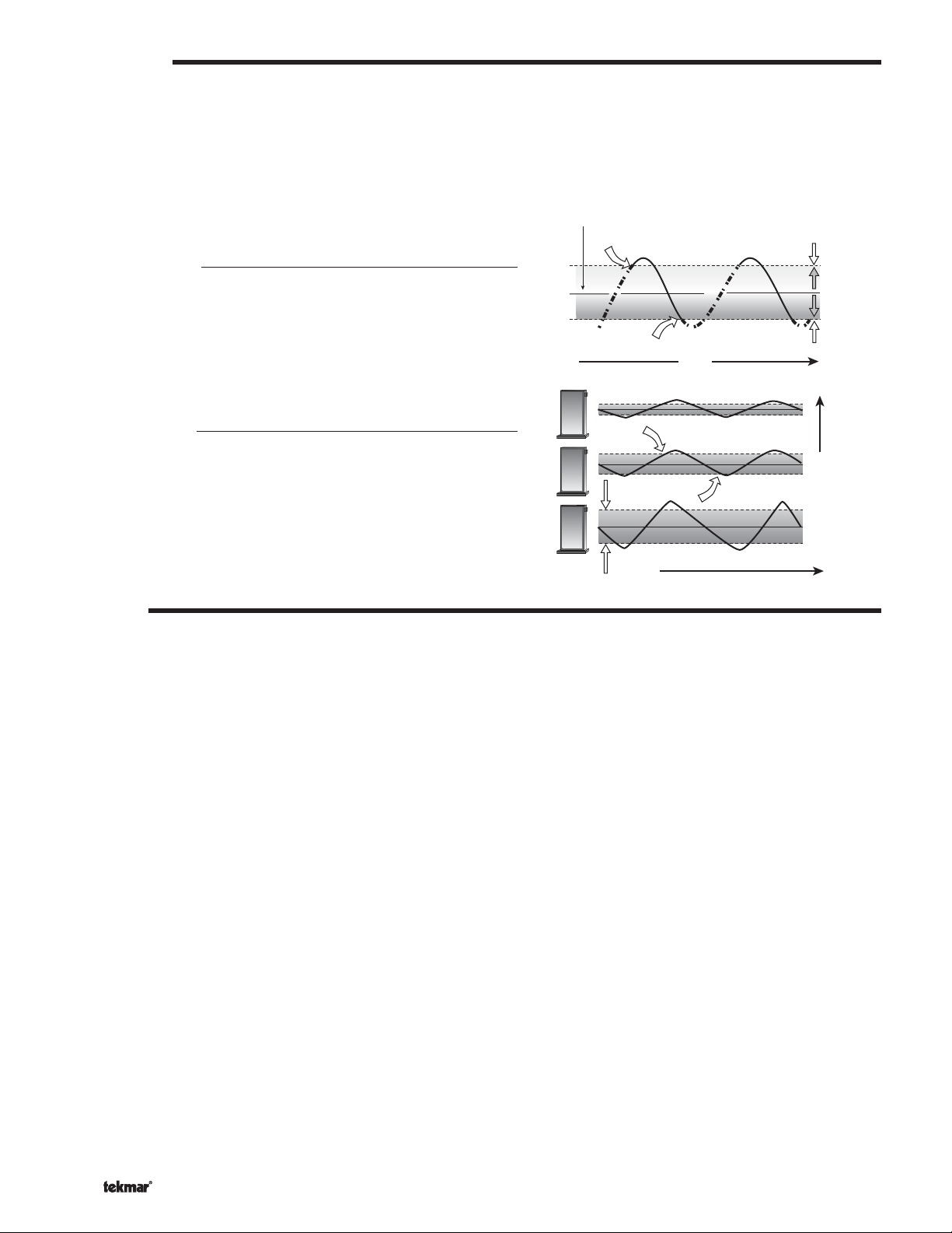
DIFFERENTIAL
A modulating boiler must be operated with a differential while operating in low fire. The boiler differential is divided around the boiler
target temperature. The boiler burner ignites at low fire when the supply water temperature is ½ of the Boiler Differential setting
below the boiler target temperature. The boiler is shut off in low fire as the supply temperature reaches at least ½ of the differential
above the boiler target temperature. With the control, either a fixed or an auto differential may be selected.
When the boiler is modulating above low fire, the differential does not apply. Instead, the modulation output signal is determined
using Proportional, Integral and Derivative (PID) logic in order to satisfy the boiler target temperature.
Desired temperature
Fixed Differential
If the user desires to have a fixed differential, this is set using the
Boiler Differential setting in the ADJUST menu.
160°F (71°C)
Boiler Off
Boiler On
165°F (74°C)
Time
e
r
u
t
a
r
e
p
m
e
T
155°F (68°C)
e
s
i
r
T
e
m
p
Differential
10°F (6°C)
e
r
a
t
u
r
e
f
a
l
l
Auto Differential
Off
If the Auto Differential is selected, the control automatically determines
the best differential as the load changes. This reduces potential short
cycling during light load conditions.
Differential
On
Increasing Load
Time
SOFT STOP
It is possible to thermally shock a boiler when it is shut off at high fire. The Soft Stop feature forces the boiler to modulate down to
a minimum before turning off. This is designed to prevent large volumes of cold air being introduced into the combustion chamber
of the boiler when it is shut off. This can occur in applications where the burner includes a fan.
Once all d emands are removed, the con trol allows for the firing r ate to be modulated down to the Minimum M odulation setting prior to t urning
off the burner. This feature is enabled by setting the Soft Stop / Off DIP switch to the Soft Stop position. If the Soft Stop / Off DIP switch
is in the Off position, the control turns off the boiler at the current firing rate once all demands are removed.
© 2009 D 263 - 03/09 10 of 36
Section C: Pump Operation
Section C1
Pump
Operation
Section C1: Pump Operation
PRIMARY PUMP OPERATION
The primary pump operates under the following conditions:
• A boiler demand is present and the control is not in Warm Weather Shut Down (WWSD).
• A DHW demand is present and DHW MODE is set to 3 or 4.
• A setpoint demand is present and Setpoint MODE is set to 3.
Primary Pump Purge
After a demand is removed, the control continues to operate the primary pump for a period of time. The maximum length of time that
the primary pump continues to run is adjustable using the Primary Pump Purge setting. The primary pump continues to run until either
the purging time has elapsed or the boiler supply temperature drops more than a differential below the Boiler Minimum setting.
OR
BOILER PUMP OPERATION (MODE 2 ONLY)
When the control is operating in Mode 2 - One Modulating Boiler and Pump, the control can operate the boiler pump on the boiler
in addition to the primary pump. The boiler pump turns on prior to the boiler firing (pre-purge) and continues to run after the boiler
is turned off (post-purge). The boiler pump pre-purge time is determined by the Boiler Mass setting. As the Boiler Mass setting is
increased, the boiler pump pre-purge time of the boiler also increases. However, if the control is operating based on a setpoint
demand, the boiler pump turns on prior to the boiler.
Boiler Pump Purge (Mode 2 Only)
The amount of time that the boiler pump continues to run after the boiler turns off is adjustable using the Boiler Pump Purge setting.
11 of 36 © 2009 D 263 - 03/09
 Loading...